Transcription
Catlike Coding › Unity › Tutorials › Advanced Renderingpublished 2017-11-30TessellationSubdividing TrianglesCreate hull and domain shaders.Subdivide triangles.Control how things get tessellated.This tutorial covers how to add support for tessellation to a custom shader. It usesthe Flat and Wireframe Shading tutorial as a basis.This tutorial is made with Unity 2017.1.0.If you don't have enough triangles, make some more.
1Hulls and DomainsTessellation is the art of cutting things into smaller parts. In our case, we're going tosubdivide triangles so we end up with smaller triangles that cover the same space.This makes it possible to add more details to geometry, though in this tutorial we'llfocus on the tessellation process itself.The GPU is capable of splitting up triangles fed to it for rendering. It does this forvarious reasons, for example when part of a triangle ends up clipped. We cannotcontrol that, but there's also a tessellation stage that we are allowed to configure.This stage sits in between the vertex and the fragment shader stages. But it's not assimple as adding just one other program to our shader. We're going to need a hullprogram and domain program.Shading with tessellation.1.1Creating a Tessellation Shader
The first step is to create a shader that has tessellation enabled. Let's put the codethat we'll need in its own file, MyTessellation.cginc, with its own include guard.#if !defined(TESSELLATION INCLUDED)#define TESSELLATION INCLUDED#endifTo clearly see that triangles get subdivided, we'll make use of the Flat WireframeShader. Duplicate that shader, rename it to Tessellation Shader and adjust its menuname.Shader "Custom/Tessellation" { }The minimum shader target level when using tessellation is 4.6. If we don't set thismanually, Unity will issue a warning and automatically use that level. We're going toadd tessellation stages to the forward base and additive passes, plus the deferredpass. Also include MyTessellation in those passes, after MyFlatWireframe.#pragma target 4.6 #include "MyFlatWireframe.cginc"#include "MyTessellation.cginc"What about the shadow pass?It is also possible to use tessellation when rendering shadows, but we won't do that inthis tutorial.Create a material that relies on this shader and add a quad to the scene that uses it. Imade the material gray so it isn't too bright, like the Flat Wireframe material.
A quad.We'll use this quad to test our tessellation shader. Note that is consists of twoisosceles right triangles. The short edges have length 1, while the long diagonaledges have length 2.1.2Hull ShadersLike geometry shaders, the tessellation stage is flexible and can work triangles,quads, or isolines. We have to tell it what surface it has to work with and feed it thenecessary data. This is the job of the hull program. Add a program for this toMyTessellation, beginning with a void function that does nothing.void MyHullProgram () {}The hull program operates on a surface patch, which is passed to it as an argument.We have to add an InputPatch parameter to make this possible.void MyHullProgram (InputPatch patch) {}A patch is a collection of mesh vertices. Like we did for the stream parameter of thegeometry function, we have to specify the data format of the vertices. We'll use theVertexDatastruct for now.void MyHullProgram (InputPatch VertexData patch) {}Shouldn't it be InputPatch InterpolatorsVertex ?As the hull stage comes after the vertex stage, logically the hull function's input typemust match the vertex function's output type. This is true, but we'll ignore this fact fornow.
As we're working with triangles, each patch will contain three vertices. This amounthas to be specified as a second template parameter for InputPatch.void MyHullProgram (InputPatch VertexData, 3 patch) {}The job of the hull program is to pass the required vertex data to the tessellationstage. Although it is fed an entire patch, the function should output only a singlevertex at a time. It will get invoked once per vertex in the patch, with an additionalargument that specifies which control point (vertex) it should work with. Theparameter is an unsigned integer with the SV OutputControlPointID semantic.void MyHullProgram (InputPatch VertexData, 3 patch,uint id : SV OutputControlPointID) {}Simply index the patch as if it were an array and return the desired element.VertexData MyHullProgram (InputPatch VertexData, 3 patch,uint id : SV OutputControlPointID) {return patch[id];}This looks like a functional program, so let's add a compiler directive to use it as ahull shader. Do this for all three shader passes that are involved.#pragma#pragma#pragma#pragmavertex MyVertexProgramfragment MyFragmentProgramhull MyHullProgramgeometry MyGeometryProgramThis will produce a few compiler errors, complaining that we haven't configured ourhull shader correctly. Like the geometry function, it needs attributes to configure it.First, we have to explicitly tell it that it's working with triangles. That's done via theUNITY domainattribute, with tri as an argument.[UNITY domain("tri")]VertexData MyHullProgram That's not enough. We also have to explicitly specify that we're outputting threecontrol points per patch, one for each of the triangle's corners.
[UNITY domain("tri")][UNITY outputcontrolpoints(3)]VertexData MyHullProgram When the GPU will create new triangles, it needs to know whether we want themdefined clockwise or counterclockwise. Like all other triangles in Unity, they shouldbe clockwise. This is controlled via the UNITY outputtopology attribute. Its argumentshould be triangle cw.[UNITY domain("tri")][UNITY outputcontrolpoints(3)][UNITY outputtopology("triangle cw")]VertexData MyHullProgram The GPU also needs to be told how it should cut up the patch, via theUNITY partitioningattribute. There are a few di"erent partitioning methods, whichwe'll investigate later. For now, just use the integer mode.[UNITY domain("tri")][UNITY outputcontrolpoints(3)][UNITY outputtopology("triangle cw")][UNITY partitioning("integer")]VertexData MyHullProgram Besides the partitioning method, the GPU also has to know into how many parts thepatch should be cut. This isn't a constant value, it can vary per patch. We have toprovide a function to evaluate this, known as a patch constant function. Let's justassume we have such a function, named MyPatchConstantFunction.[UNITY domain("tri")][UNITY outputcontrolpoints(3)][UNITY outputtopology("triangle cw")][UNITY partitioning("integer")][UNITY xData MyHullProgram
1.3Patch Constant FunctionsHow a patch is to be subdivided is a property of the patch. This means that the patchconstant function is only invoked once per patch, not once per control point. That'swhy it's referred to as a constant function, being constant across the entire patch.E"ectively, this function is a sub-stage operating in parallel with MyHullProgram.Inside a hull shader.To determine how to subdivide a triangle, the GPU uses four tessellation factors.Each edge of the triangle patch gets a factor. There's also a factor for the inside ofthe triangle. The three edge vectors have to be passed along as a float array with theSV TessFactorsemantic. The inside factor uses the SV InsideTessFactor semantic. Let'screate a struct for that.struct TessellationFactors {float edge[3] : SV TessFactor;float inside : SV InsideTessFactor;};The patch constant function takes a patch as an input parameter and outputs thetessellation factors. Let's now create this missing function. Simply have it set allfactors to 1. This will instruct the tessellation stage to not subdivide the patch.TessellationFactors MyPatchConstantFunction (InputPatch VertexData, 3 patch) {TessellationFactors f;f.edge[0] 1;f.edge[1] 1;f.edge[2] 1;f.inside 1;return f;}1.4Domain Shaders
At this point, the shader compiler will complain that a shader cannot have atessellation control shader without a tessellation evaluation shader. The hull shaderis only part of what we need to get tessellation working. Once the tessellation stagehas determined how the patch should be subdivided, it's up to the geometry shaderto evaluate the result and generate the vertices of the final triangles. So let's create afunction for our domain shader, again starting with a stub.void MyDomainProgram () {}Both the hull and domain shader act on the same domain, which is a triangle. Wesignal this again via the UNITY domain attribute.[UNITY domain("tri")]void MyDomainProgram () {}The domain program is fed the tessellation factors that were used, as well as theoriginal patch, which is of type OutputPatch in this case.[UNITY domain("tri")]void MyDomainProgram (TessellationFactors factors,OutputPatch VertexData, 3 patch) {}While the tessellation stage determines how the patch should be subdivided, itdoesn't generated any new vertices. Instead, it comes up with barycentric coordinatesfor those vertices. It's up to the domain shader to use those coordinates to derive thefinal vertices. To make this possible, the domain function is invoked once per vertexand is provided the barycentric coordinates for it. They have the SV DomainLocationsemantic.[UNITY domain("tri")]void MyDomainProgram (TessellationFactors factors,OutputPatch VertexData, 3 patch,float3 barycentricCoordinates : SV DomainLocation) {}Inside the function, we have to generate the final vertex data.
[UNITY domain("tri")]void MyDomainProgram (TessellationFactors factors,OutputPatch VertexData, 3 patch,float3 barycentricCoordinates : SV DomainLocation) {VertexData data;}To find the position of this vertex, we have to interpolate across the original triangledomain, using the barycentric coordinates. The X, Y, and Z coordinates determine theweights of the first, second, and third control points.VertexData data;data.vertex patch[0].vertex * barycentricCoordinates.x patch[1].vertex * barycentricCoordinates.y patch[2].vertex * barycentricCoordinates.z;We have to interpolate all vertex data in the same way. Let's define a convenientmacro for that, which can be used for all vector sizes.////////data.vertex patch[0].vertex * barycentricCoordinates.x patch[1].vertex * barycentricCoordinates.y patch[2].vertex * barycentricCoordinates.z;#define MY DOMAIN PROGRAM INTERPOLATE(fieldName) data.fieldName \patch[0].fieldName * barycentricCoordinates.x \patch[1].fieldName * barycentricCoordinates.y \patch[2].fieldName * barycentricCoordinates.z;MY DOMAIN PROGRAM INTERPOLATE(vertex)Besides the position, also interpolate the normal, tangent, and all UV coordinates.MY DOMAIN PROGRAM INTERPOLATE(vertex)MY DOMAIN PROGRAM INTERPOLATE(normal)MY DOMAIN PROGRAM INTERPOLATE(tangent)MY DOMAIN PROGRAM INTERPOLATE(uv)MY DOMAIN PROGRAM INTERPOLATE(uv1)MY DOMAIN PROGRAM INTERPOLATE(uv2)The only thing that we do not interpolate are instance IDs. As Unity does not supportGPU instancing and tessellation at the same time, there's no point in copying this ID.To prevent compiler errors, remove the multi-compile directives from the threeshader passes. This wil also remove the instancing option from the shader's GUI.
////#pragma multi compile instancing#pragma instancing options lodfade force same maxcount for glIs it possible to use instancing and tessellation together?At the moment, that's not the case. Keep in mind that GPU instancing is useful whenrendering the same object many times. As tessellation is expensive and about addingdetails, they're usually not a good combination. If you want to have many instances ofsomething that should use tessellation up close, you could use a LOD group. Have LOD0 use a non-instanced tessellated material, while all other LOD levels use an instancednon-tessellated material.We now have a new vertex, which will be send to either the geometry program or theinterpolator after this stage. But these programs expect InterpolatorsVertex data, notVertexData.To solve this, we have the domain shader take over the responsibilities ofthe original vertex program. This is done by invoking MyVertexProgram inside it—likeany other function—and return its result.[UNITY domain("tri")]InterpolatorsVertex MyDomainProgram (TessellationFactors factors,OutputPatch VertexData, 3 patch,float3 barycentricCoordinates : SV DomainLocation) { return MyVertexProgram(data);}Now we can add the domain shader to our three shader passes, but we'll still geterrors.#pragma hull MyHullProgram#pragma domain MyDomainProgram1.5Control PointsMyVertexProgramonly has to be invoked once, it's just that we changed where thishappens. But we still have to specify a vertex program to be invoked during thevertex shader stage, which sits before the hull shader. We don't have to do anythingat that point, so we can make do with a function that simply passes through thevertex data unmodified.
VertexData MyTessellationVertexProgram (VertexData v) {return v;}Have our three shader passes use this function for its vertex program from now on.#pragma vertex MyTessellationVertexProgramThis will produce yet another compiler error, complaining about a reuse of theposition semantic. To make this work, we have to use an alternative output struct forour vertex program, which uses the INTERNALTESSPOS semantic for the vertex position.The rest of the struct is the same as VertexData, except that it never has an instanceID. As this vertex data is used as control points for the tessellation process, let'sname it TessellationControlPoint.struct TessellationControlPoint {float4 vertex : INTERNALTESSPOS;float3 normal : NORMAL;float4 tangent : TANGENT;float2 uv : TEXCOORD0;float2 uv1 : TEXCOORD1;float2 uv2 : TEXCOORD2;};Change MyTessellationVertexProgram so it puts the vertex data into a control pointstruct and returns that.TessellationControlPoint MyTessellationVertexProgram (VertexData v) {TessellationControlPoint p;p.vertex v.vertex;p.normal v.normal;p.tangent v.tangent;p.uv v.uv;p.uv1 v.uv1;p.uv2 v.uv2;return p;}Next, MyHullProgram must also change so it works with TessellationControlPointinstead of VertexData. Only its parameter type needs to change.TessellationControlPoint MyHullProgram (InputPatch TessellationControlPoint, 3 patch,uint id : SV OutputControlPointID) {return patch[id];}
The same goes for the patch constant function.TessellationFactors MyPatchConstantFunction (InputPatch TessellationControlPoint, 3 patch) { }And the domain program's parameter type has to change as well.InterpolatorsVertex MyDomainProgram (TessellationFactors factors,OutputPatch TessellationControlPoint, 3 patch,float3 barycentricCoordinates : SV DomainLocation) { }At this point we finally have a correct tessellation shader. It should compile andrender the quad as before. It isn't subdivided yet, because the tessellation factors arealways 1.
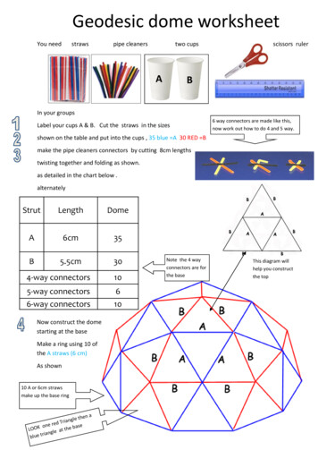
2Subdividing TrianglesThe point of the whole tessellation setup is that we can subdivide patches. Thisallows us to replace a single triangle with a collection of smaller triangles. We'regoing to do that now.2.1Tessellation FactorsHow a triangle patch gets subdivided is controlled by its tessellation factors. Wedetermine these factors in MyPatchConstantFunction. Currently, we have them all set to1, which produces no visual change. The hull, tessellation, and domain shader stagesare working, but they're passing though the original vertex data and generatenothing new. To change this, set all factors to 2.TessellationFactors MyPatchConstantFunction (InputPatch TessellationControlPoint, 3 patch) {TessellationFactors f;f.edge[0] 2;f.edge[1] 2;f.edge[2] 2;f.inside 2;return f;}Tessellation factors 2.The triangles now do get subdivided. All their edges have been split into two subedges each, leading to three new vertices per triangle. Also, yet another vertex hasbeen added at the center of each triangle. This made it possible generate twotriangles per original edge, so the original triangles have been replaced by sixsmaller triangles each. As the quad is made of two triangles, we're now gettingtwelve triangles in total.
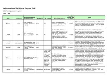
If you set all factors to 3 instead, each edge will be split into three sub-edges. In thiscase, there won't be a center vertex. Instead, three vertices are added inside theoriginal triangle, forming a smaller inner triangle. The outer edges will be connectedto this inner triangle with triangle strips.Tessellation factors 3.When the tessellation factors are even, there will be a single center vertex. When theyare odd, there will be a center triangle instead. If we use larger tessellation factors,we end up with multiple nested triangles. Each step towards the center, the amountby which the triangle gets subdivided decreases by two, until we end up with eitherone or zero sub-edges.Tessellation factors 4–7.
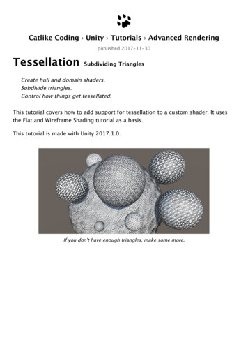
2.2Di!erent Edge and Inside FactorsHow the triangles get subdivided is controlled by the inside tessellation factor. Theedge factors can be used to override the amount by which their respective edges aresubdivided. This only a"ects the original patch edges, not the generated innertriangles. To clearly see this, set the inside factor to 7 while keeping the edge factors1.f.edge[0] 1;f.edge[1] 1;f.edge[2] 1;f.inside 7;Factor 7 inside, but 1 outside.E"ectively, the triangle is tessellated using the factor 7, after which the outer ring oftriangles is discarded. Each edge is then subdivided using its own factor, after whicha triangle strip is generated to stitch the edge and inner triangle together.It is also possible for the edge factors to be greater than the inside factor. Forexample, set the edge factors to 7 while leaving the inside factor at 1.f.edge[0] 7;f.edge[1] 7;f.edge[2] 7;f.inside 1;
Factor 1 inside, but 7 outside.In this case, the inside factor is forced to act as if it were 2, because otherwise nonew triangles could be generated.What about using di!erent factors for each edge?This is possible, but the shader compiler doesn't like it when you do this with hardcoded values. You might end up with with shader compiler errors when you try that withsome values. We'll see why di"erent factors are useful later.2.3Variable FactorsHard-coded tessellation factors aren't very useful. So let's make it configurable,starting with a single uniform factor.float TessellationUniform; TessellationFactors MyPatchConstantFunction (InputPatch TessellationControlPoint, 3 patch) {TessellationFactors f;f.edge[0] TessellationUniform;f.edge[1] TessellationUniform;f.edge[2] TessellationUniform;f.inside TessellationUniform;return f;}Add a property for this to our shader. Set its range to 1–64. No matter how high afactor we'd like to use, the hardware has a limit of 64 subdivisions per patch.TessellationUniform ("Tessellation Uniform", Range(1, 64)) 1
To be able to edit this factor, add a DoTessellation method to MyLightingShaderGUI todisplay it in its own section.void DoTessellation () {GUILayout.Label("Tessellation", EditorStyles.boldLabel);EditorGUI.indentLevel 2;editor.ShaderProperty(FindProperty(" GUI.indentLevel - 2;}Invoke this method inside OnGUI, between the rendering mode and the wireframesection. Only do this if the required property exists.public override void OnGUI (MaterialEditor editor, MaterialProperty[] properties) { DoRenderingMode();if (target.HasProperty(" TessellationUniform")) {DoTessellation();}if (target.HasProperty(" WireframeColor")) {DoWireframe();} }Catlike Coding@catlikecodingSDConfigurable uniform tessellation.76.1K views2.4Fractional Factors
Even though we use a float to set the tessellation factors, we always end up with awhole number of equivalent subdivisions per edge. That's because we're using theinteger partitioning mode. While it is a good mode to see how tessellation works, itprevents us from smoothly transitioning between subdivision levels. Fortunately,there are also fractional partitioning modes. Let's change the mode to fractional odd.[UNITY domain("tri")][UNITY outputcontrolpoints(3)][UNITY outputtopology("triangle cw")][UNITY partitioning("fractional odd")][UNITY llationControlPoint MyHullProgram Catlike Coding@catlikecodingSDFractional odd partitioning.78.7K viewsWhen using a whole odd factor, the fractional odd partitioning mode produces thesame results as the integer mode. But when transitioning between odd factors, extraedge subdivisions will be split o" and grow, or shrink and merge. This means edgesare no longer always split in segments of equal length. The advantage of thisapproach is that transitions between subdivision levels are now smooth.It is also possible to use the fractional even mode. It works the same way, exceptthat it is based on even factors.
Catlike Coding@catlikecodingSDFractional even partitioning.81.3K viewsThe fractional odd mode is often used because it can deal with a factor of 1, whilethe fractional even mode is forced to use a minimum level of 2.
3Tessellation HeuristicsWhat are the best tessellation factors? That is the main question that you have to askyourself when working with tessellation. There isn't a single objective answer to thisquestion. In general, the best you can do is come up with some metric that acts as aheuristic that produces good results. In this tutorial, we'll support two simpleapproaches.3.1Edge FactorsAlthough tessellation factors have to be provided per edge, you don't have to basethe factors on the edges directly. For example, you could determine factors pervertex, then average them per edge. Maybe the factors are stored in a texture. In anycase, it's handy to have a separate function to determine the factor, given the twocontrol points of an edge. Create such a function, simply returning the uniform valuefor now.float TessellationEdgeFactor (TessellationControlPoint cp0, TessellationControlPoint cp1) {return TessellationUniform;}Use this function for the edge factors inside MyPatchConstantFunction.TessellationFactors MyPatchConstantFunction (InputPatch TessellationControlPoint, 3 patch) {TessellationFactors f;f.edge[0] TessellationEdgeFactor(patch[1], patch[2]);f.edge[1] TessellationEdgeFactor(patch[2], patch[0]);f.edge[2] TessellationEdgeFactor(patch[0], patch[1]);f.inside TessellationUniform;return f;}For the inside factor, we'll simply use the average of the edge factors.f.inside (f.edge[0] f.edge[1] f.edge[2]) * (1 / 3.0);3.2Edge Length
As the edge tessellation factors control how much we subdivide the edges of theoriginal triangle, it makes sense to base this factor on the length of those edges. Forexample, we could specify a desired triangle edge length. If we end up with triangleedges longer than that, we should subdivide them by the desired length. Add avariable for that.float TessellationUniform;float TessellationEdgeLength;Add a property as well. Let's use a range from 0.1 to 1, with a default of 0.5. This isin world space units.TessellationUniform ("Tessellation Uniform", Range(1, 64)) 1TessellationEdgeLength ("Tessellation Edge Length", Range(0.1, 1)) 0.5We need a shader feature to make it possible to switch between uniform and edgebased tessellation. Add the required directive to all our three passes, using theTESSELLATION EDGE keyword.#pragma shader feature TESSELLATION EDGENext, add an enum type to MyLightingShaderGUI to represent the tessellation modes.enum TessellationMode {Uniform, Edge}Then adjust DoTessellation so it can switch between both modes, using an enumpopup. It works similar to how DoSmoothness controls the smoothness modes. In thiscase, uniform is the default mode, requiring no keyword.
void DoTessellation () {GUILayout.Label("Tessellation", EditorStyles.boldLabel);EditorGUI.indentLevel 2;TessellationMode mode TessellationMode.Uniform;if (IsKeywordEnabled(" TESSELLATION EDGE")) {mode );mode bel("Mode"), mode);if (EditorGUI.EndChangeCheck()) {RecordAction("Tessellation Mode");SetKeyword(" TESSELLATION EDGE", mode TessellationMode.Edge);}if (mode TessellationMode.Uniform) {editor.ShaderProperty(FindProperty(" TessellationUniform"),MakeLabel("Uniform"));}else {editor.ShaderProperty(FindProperty(" TessellationEdgeLength"),MakeLabel("Edge Length"));}EditorGUI.indentLevel - 2;}Using edge mode.Now we have to adjust TessellationEdgeFactor. When TESSELLATION UNIFORM isdefined, determine the world positions of both points, then compute the distancebetween them. This is the edge length in world space. The edge factor is equal tothis length divided by the desired length.float TessellationEdgeFactor (TessellationControlPoint cp0, TessellationControlPoint cp1) {#if defined( TESSELLATION EDGE)float3 p0 mul(unity ObjectToWorld, float4(cp0.vertex.xyz, 1)).xyz;float3 p1 mul(unity ObjectToWorld, float4(cp1.vertex.xyz, 1)).xyz;float edgeLength distance(p0, p1);return edgeLength / TessellationEdgeLength;#elsereturn TessellationUniform;#endif}
Di"erent quad scales, same desired edge length.Because we're now using the edge length to determine an edge's tessellation factor,we can end up with di"erent factors per edge. You can see this happen for the quad,as the diagonal edges are longer than the other edges. It also becomes obvious whenusing a nonuniform scale for the quad, stretching it in one dimension.Stretched quad.To make this work, it is essential that patches that share an edge both end up usingthe same tessellation factor for that edge. Otherwise, the generated vertices won'tmatch along that edge, which can produce visible gaps in the mesh. In our case,we're using the same logic for all edges. The only di"erence can be the order of thecontrol point arguments. Because of floating-point limitations, this could technicallyproduce di"erent factors, but the di"erence will be so minuscule that it would beunnoticeable.3.3Edge Length in Screen SpaceWhile we can now control the triangle edge length in world space, this does notcorrespond to how they appear in screen space. The point of tessellation is to addmore triangles when they are needed. So we don't want to subdivide triangles thatalready appear small. So let's use the screen-space edge length instead.First, change the range of our edge length property. Instead of world units, we'regoing to use pixels, so a range like 5–100 makes more sense.
TessellationEdgeLength ("Tessellation Edge Length", Range(5, 100)) 50Replace the world-space calculations with their screen-space equivalents. To do this,the points have to be converted to clip space instead of world space. Then theirdistance is determined in 2D, using their X and Y coordinates, divided by their Wcoordinates to project them onto the screen.//////float3 p0 mul(unity ObjectToWorld, float4(cp0.vertex.xyz, 1)).xyz;float3 p1 mul(unity ObjectToWorld, float4(cp1.vertex.xyz, 1)).xyz;float edgeLength distance(p0, p1);float4 p0 UnityObjectToClipPos(cp0.vertex);float4 p1 UnityObjectToClipPos(cp1.vertex);float edgeLength distance(p0.xy / p0.w, p1.xy / p1.w);return edgeLength / TessellationEdgeLength;Now we have a result in clip space, which is a uniform cube with size 2 that fits thedisplay. To convert to pixels, we have to scale by the display size in pixels. Actually,because the display is rarely square, to get the most exact result, we should scale theX and Y coordinates separately, before determining the distance. But let's su#ce withsimply scaling by the screen height, to see how it looks.return edgeLength * ScreenParams.y / TessellationEdgeLength;Same world size, di"erent screen size.Our triangle edges now get subdivided based on how large they are rendered.Position, rotation, and scale all influence this, relative to the camera. As a result, theamount of tessellation changes when things are in motion.
Shouldn't we use half the screen height?As the clip space cube's range is 1–1, two units correspond to the full height—andwidth—of the display. This means we end up with double the actual size, overestimatinghow large our edges are. The result is that we're e"ectively targeting half the edgelength than expected. At least, that's the case for perfectly vertical edges, because we'renot using the exact screen dimensions anyway. The main point of using the screenheight is to make the tessellation dependent on the display resolution. Whether the edgelengths match the exact value of our slider doesn't really matter.3.4Using the View DistanceA downside of purely relying on the visual length of edges is that edges that are longin world space can end up very small in screen space. This could lead to these edgesnot being subdivided at all, while other edges are subdivided a lot. This isundesirable when tessellation is used to add details up close or to generate complexsilhouettes.A di"erent approach is to go back to using the world-space edge length, but adjustthe factor based on the view distance. The further away something is, the smaller itshould appear visually, thus the less tessellation it needs. So divide the edge lengthby the distance between the edge and the camera. We can use the midpoint of theedge to determine this distance.////////float4 p0 UnityObjectToClipPos(cp0.vertex);float4 p1 UnityObjectToClipPos(cp1.vertex);float edgeLength distance(p0.xy / p0.w, p1.xy / p1.w);return edgeLength * ScreenParams.y / TessellationEdgeLength;float3 p0 mul(unity ObjectToWorld, float4(cp0.vertex.xyz, 1)).xyz;float3 p1 mul(unity ObjectToWorld, float4(cp1.vertex.xyz, 1)).xyz;float edgeLength distance(p0, p1);float3 edgeCenter (p0 p1) * 0.5;float viewDistance distance(edgeCenter, WorldSpaceCameraPos);return edgeLength / ( TessellationEdgeLength * viewDistance);We can still keep tessellation dependent on the display size, by simply factoring thescreen height into it and keeping our 5–100 slider r
This tutorial is made with Unity 2017.1.0. If you don't have enough triangles, make some more. 1 Hulls and Domains Tessellation is the art of cutting things into smaller parts. In our case, we're going to subdivide triangles so we