Transcription
Configuration Guide5991-3823December 2005Configuring T1 and E1 WAN InterfacesThis configuration guide explains the processes for configuring yourSecure Router Operating System (SROS) T1/E1 product for somecommon applications. This guide discusses configuring the T1/E1interfaces, various Layer 2 (L2) protocols, many-to-one Network AddressTranslation (NAT), and adding static routes to the route table. For moredetailed information regarding specific command syntax, refer to theSROS Command Line Interface Reference Guide on your ProCurve SROSDocumentation CD.This guide consists of the following sections: Overview of T1/E1 WAN Applications on page 2 Physical Interface Configurations (T1, E1, and Ethernet) on page 3 Configuring Layer 2 Protocols (Frame Relay, PPP, HDLC) on page 7 Binding Physical and Virtual Interfaces on page 17 Creating Access Lists and Policies on page 17 Configuring Routing Information (Static Routes) on page 22 Configuration Examples on page 2461195880L1-29.7APrinted in the USA1
Overview of T1/E1 WAN ApplicationsUnderstanding SROS Queuing MethodsOverview of T1/E1 WAN ApplicationsWide area networks (WANs) provide the mechanism for connecting remote sites together and connectingyour local network to the Internet through a connection to an ISP. WANs use a variety of physicaltransports; T1/E1 connections are a common means of transport.T1 circuits are generally used in domesticapplications, while E1 circuits are widely deployed internationally. T1/E1 circuits are a relativelyinexpensive investment because they allow remote sites to share corporate resources at other locations andthus eliminate the need for redundant equipment at multiple locations. For example, a corporation withmany small branch offices can consolidate their Internet access through a single interface and avoid payingfor Internet connectivity at each small office. Not only does this provide a cost savings, but it also gives thecorporation’s IT department more control over Internet usage and protection at each of the branch offices.Many companies have centralized databases that must be used by employees at remote locations. Creatinga WAN connection between the centralized database and the remote location allows the remote users fullaccess to the resources.Configuring T1/E1 WAN applications includes six steps:1. Configure the physical interfaces (Ethernet and WAN interfaces)2. Configure the L2 protocol(s)3. Bind the physical and virtual (L2) interfaces4. Create access lists and policies (including NAT parameters)5. Apply the policies to interfaces6. Configure the routing information (static routes, OSPF, RIP, etc.)These configuration steps are explained on the following pages. Each step includes a brief discussion ofavailable settings, but does not elaborate on parameters that are normally left in the default state. Inaddition, each step provides a sample command listing for a generic configuration. Specific exampleconfigurations (with configuration scripts) are provided at the end of this document. For detailedinformation regarding WAN configuration parameters, refer to the documentation provided on yourProCurve SROS Documentation CD.25991-3823
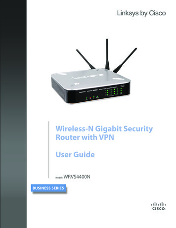
Understanding SROS Queuing MethodsPhysical Interface Configurations (T1, E1, and Ethernet)Physical Interface Configurations (T1, E1, and Ethernet)NoteInterface Modules use a slot/port notation for interface identification (e.g., t1 1/1). Allnon-modular interfaces built into the base unit are identified using 0 as the slot number(e.g. eth 0/1).To begin configuring physical interfaces, you must first activate the appropriate interface configurationmode from the Global configuration prompt. For example, enter the following commands to activate theinterface configuration mode for the first T1 interface on a T1 module inserted in slot 1:ProCurve enableProCurve#config terminalProCurve(config)#interface t1 1/1ProCurve(config-t1 1/1)#All interfaces are disabled by default and must be activated using the no shutdown command. Interfaceswill not be able to pass data until this command is entered.Interfaces can also be configured using the Web GUI. To activate the configuration page for a physicalinterface located in the unit, click on the Physical Interfaces link under the System heading in thenavigation bar on the left side of the screen (see below). Select the physical interface to configure from thelist.5991-38233
Configuring Ethernet InterfacesUnderstanding SROS Queuing MethodsConfiguring Ethernet InterfacesEthernet interface configuration can range from assigning an IP address and activating the interface toactivating the DHCP client to poll the network DHCP server to gain an IP address. Standard Ethernetconfigurations generally contain an IP address, a speed, and a duplex setting. By default, all Secure RouterEthernet interfaces are configured to auto-detect the speed (as 10 or 100 Mbps) and are set to full-duplex.For most cases, these settings should suffice and will not be changed from the default state.The following example commands configure an IP address of (10.10.0.7/24) and activates the interface forthe eth 0/1 interface:ProCurve enableProCurve#config terminalProCurve(config)#interface eth 0/1ProCurve(config-eth 0/1)#ip address 10.10.0.7 255.255.255.0ProCurve(config-eth 0/1)#no shutdownProCurve(config-eth 0/1)#exitProCurve(config)#The following example configures an IP address of (10.10.0.7/24) and activates the interface for theeth 0/1 interface using the Web GUI:45991-3823
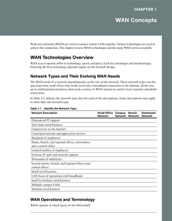
Understanding SROS Queuing MethodsConfiguring Ethernet InterfacesConfiguring T1 InterfacesThere are four main settings to consider when configuring T1 network interfaces. The line coding(coding), framing format (framing), active channels (tdm-group), and clock source (clock source) mustall be configured to match the circuit supplied by your network provider. By default, all Secure Router T1interfaces are configured for ESF (framing esf) and B8ZS (coding b8zs), and to recover clocking from thenetwork circuit (clock source line). Generally, the line coding, framing format, and clock source defaultvalues will be the correct ones for your application and should not be changed.Each configured T1 interface must have the active channels specified using the tdm-group commandbecause there are no default TDM groups defined. The active channels are entered as a single numberrepresenting 1 of the 24 T1 channel timeslots or as a contiguous group of channels.The following example commands specify the configuration parameters required for a standard T1interface:ProCurve enableProCurve#config terminalProCurve(config)#interface t1 1/1ProCurve(config-t1 1/1)#tdm-group 1 timeslots 1-24ProCurve(config-t1 1/1)#no shutdownProCurve(config-t1 1/1)#exitThe following example specifies the configuration parameters required for a standard T1 interface usingthe Web GUI:T1 InterfaceConfigurationParameters5991-38235
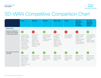
Configuring Ethernet InterfacesUnderstanding SROS Queuing MethodsConfiguring E1 InterfacesThere are four main settings to consider when configuring E1 network interfaces. The line coding(coding), framing format (framing), active channels (tdm-group), and clock source (clock source) mustall be configured to match the circuit supplied by your network provider. By default, all SROS router E1interfaces are configured for standard multi-frame without the optional CRC4 error correction (no framingcrc4), and to recover clocking from the network circuit (clock source line). Generally, the line coding,framing format, and clock source default values will be the correct ones for your application and shouldnot be changed.Each configured E1 interface must have the active channels specified using the tdm-group commandbecause there are no default TDM groups. The active channels are entered as a single number representing1 of the 31 E1 channel timeslots or as a contiguous group of channels.The following example commands specify the configuration parameters required for a standard E1interface:ProCurve enableProCurve#config terminalProCurve(config)#interface e1 1/1ProCurve(config-e1 1/1)#tdm-group 1 timeslots 1-31ProCurve(config-e1 1/1)#no shutdownProCurve(config-e1 1/1)#exitThe following example specifies the configuration parameters required for a standard E1 interface usingthe Web GUI:E1 InterfaceConfigurationParameters65991-3823
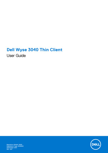
Understanding SROS Queuing MethodsConfiguring Layer 2 Protocols (Frame Relay, PPP, HDLC)Configuring Layer 2 Protocols (Frame Relay, PPP, HDLC)Each WAN connection in your SROS product must contain a physical interface (T1, E1, ADSL, etc.) and aLayer 2 protocol (ATM, Frame Relay/multilink Frame Relay, PPP/multilink PPP, or HDLC). The physicalinterface provides the actual bandwidth between your device and the network provider. The Layer 2protocol defines how the data is packaged and presented on the physical interface. Layer 2 protocols mustbe configured to match the protocol provided on the circuit. For example, configuring theSROS product for PPP operation on a Frame Relay circuit would not be successful.SROS currently supports the following Layer 2 protocols for T1/E1 physical links: Frame Relay, including multilink Frame Relay (FRF.16) point-to-point protocol (PPP), including multilink PPP high-level data link control (HDLC) protocolConfiguring the Frame Relay Interfaces (and Sub-Interfaces)There are two settings to consider when configuring Frame Relay interfaces. The interface type(frame-relay intf-type) and signaling type (frame-relay lmi-type) must be configured to match thespecifications supplied on your Frame Relay circuit by your network provider. By default, all SROS FrameRelay interfaces are configured as a DTE interface (frame-relay intf-type dte) with Annex D signaling(frame-relay lmi-type ansi).Frame relay interfaces have a sub-interface component for each PVC which must also be configured. EachFrame Relay sub-interface contains a DLCI (frame-relay interface-dlci) and IP address (ip address). Youmust manually configure the Frame Relay sub-interface DLCI and IP address because there are no defaultDLCIs or IP addresses defined. Access policies are also applied at the sub-interface level (see CreatingAccess Lists and Policies on page 17).Each PVC should also have a configured committed burst value (frame-relay bc) which is equivalent tothe committed information rate (CIR) given to you by your network provider. PVCs will also have anegotiated burst rate (frame-relay be) which is equivalent to the excess information rate (EIR) given toyou by your network provider. Both the CIR and EIR should be decided on by you and your serviceprovider when defining your service agreement. To determine the appropriate committed burst value andEIR, you need to know the CIR and physical bandwidth for both the local and remote connections. If oneside transmits data at a rate much higher than the other side’s CIR (or physical bandwidth), packets will bedropped causing a decrease in efficiency. A general rule is to provision the committed burst value with theremote side CIR and configure the EIR with the difference between the CIR and the actual physicalbandwidth at the location. The committed burst value plus the EIR should not be greater than the physicalbandwidth.The following commands specify the configuration parameters required for a standard Frame Relayinterface:ProCurve enableProCurve#config terminalProCurve(config)#interface fr 2ProCurve(config-fr 2)#no shutdownProCurve(config-fr 2)#exitNote5991-3823The Web GUI automatically chooses the label for the created Frame Relay Interface.Labels are chosen sequentially starting at 1.7
Configuring the Frame Relay Interfaces (and Sub-Interfaces)Understanding SROS Queuing MethodsThe following commands specify the configuration parameters required for a standard Frame Relaysub-interfaces:ProCurve(config)#interface fr 2.16ProCurve(config-fr 2.16)#frame-relay interface-dlci 16ProCurve(config-fr 2.16)#frame-relay bc 768000ProCurve(config-fr 2.16)#frame-relay be 768000ProCurve(config-fr 2.16)#ip address 192.168.72.1 /30ProCurve(config-fr 2.16)#no shutdownProCurve(config-fr 2.16)#exitNoteLabeling the Frame Relay sub-interfaces using the DLCI (such as 1.16 indicating a DLCIof 16) is useful for quickly determining (from a configuration printout) which sub-interfacecorresponds to which PVC. The Web GUI automatically uses the configured DLCI for thesub-interface label.L2 protocol interfaces are created in the Web GUI on the configuration page for the physical interface towhich they are bound. For example, to create the Frame Relay interface to bind to a T1 interface, activatethe T1 interface configuration page and specify Frame Relay in the Encapsulation section:Create theL2 ProtocolInterface85991-3823
Understanding SROS Queuing MethodsConfiguring the Frame Relay Interfaces (and Sub-Interfaces)After clicking Apply, the Frame Relay configuration page displays:Click the Add button (in the Permanent Virtual Circuits section) to create a new Frame Relaysub-interface.5991-38239
Configuring the Frame Relay Interfaces (and Sub-Interfaces)Understanding SROS Queuing MethodsSpecify the Frame Relay sub-interface configuration parameters on the DLCI Configuration page:Click Apply to create the Frame Relay sub-interface.Multilink Frame Relay OperationMultilink Frame Relay operation increases bandwidth on your Frame Relay service by aggregatingmultiple physical links into a single logical bundle. All the physical links in a multilink bundle aretreated as a single entity by the system, allowing each PVC on the connection to dynamically share thetotal bandwidth of the bundle. Single data packets can be fragmented into smaller pieces which may ormay not be transmitted to the network over the same physical link. Multilink Frame Relay devicesbalance the transmitted information to evenly use all the physical links in a bundle.SROS products support multilink Frame Relay (FRF.16), requiring that the multilink operation besupported from the network provider. Remote side Frame Relay connections are unaffected bymultilink operation; the multilink FRF.16 functionality provides an effective way to increase the totalbandwidth at a single site between the Frame Relay device and the network provider.Physical links can be dynamically added and removed from the logical bundle, so a failure on onephysical link does not halt the overall operation of the bundle. Since all PVCs have access to the entirebundle bandwidth, failure of a single physical connection in the bundle does not decrease efficiency.Multilink Frame Relay requires minimal configuration in your SROS product. You must first enablemultilink operation on the Frame Relay interface (not sub-interface) and then bind the multiplephysical interfaces to the single Frame Relay interface. Optionally, you can set a bundle ID (label for105991-3823
Understanding SROS Queuing MethodsConfiguring the Frame Relay Interfaces (and Sub-Interfaces)the bundle), but SROS will automatically define one based on the specified Frame Relay interface. Forexample, if multilink operation is enabled on a Frame Relay interface labeled fr 1, the bundle IDbecomes mfr1 (with the 1 corresponding to the label of the Frame Relay interface). Bundle IDs can becharacter strings containing 1 to 48 characters. Manually defining the bundle ID can make it easier todifferentiate between bundles in systems with more than one multilink bundle. In systems with a singlemultilink bundle, leaving the bundle ID to the default value is the easiest solution.The following commands specify the configuration parameters required for a standard multilink FrameRelay interface:ProCurve enableProCurve#config terminalProCurve(config)#interface fr 1ProCurve(config-fr 1)#frame-relay multilinkProCurve(config-fr 1)#no shutdownProCurve(config-fr 1)#exitNow, bind multiple physical interfaces to the same multilink Frame Relay interface:ProCurve(config)#bind 1 t1 3/1 1 fr 1ProCurve(config)#bind 2 t1 3/2 2 fr 1ProCurve(config)#bind 3 t1 3/3 3 fr 1To create a standard multilink Frame Relay interface using the Web GUI, follow the same procedurefor a standard Frame Relay interface (see Configuring the Frame Relay Interfaces (andSub-Interfaces) on page 7) and click the Multilink checkbox. Interfaces configured for multilinkoperation can be bound to more than one physical interface. To bind a physical interface to an existingmultilink interface, specify multilink operation and select the interface from the drop down list.MultilinkL2 InterfaceDrop DownList5991-382311
Configuring PPP InterfacesUnderstanding SROS Queuing MethodsConfiguring PPP InterfacesThere are two settings to consider when configuring PPP interfaces: the IP address and the maximumtransmission unit (MTU). There are no default IP addresses, so each interface must be manuallyprogrammed with the appropriate address (ip address). All SROS router PPP interfaces have a defaultMTU of 1500 bytes, which works for most applications.The following commands specify the configuration parameters required for a standard PPP interface:ProCurve enableProCurve#config terminalProCurve(config)#interface ppp 1ProCurve(config-ppp 1)#ip address 172.22.15.2 /30ProCurve(config-ppp 1)#no shutdownProCurve(config-ppp 1)#exitL2 protocol interfaces are created in the Web GUI on the configuration page for the physical interface towhich they are bound. For example, to create the PPP interface to bind to a T1 interface, activate the T1interface configuration page and specify PPP in the Encapsulation section:Create theL2 ProtocolInterface125991-3823
Understanding SROS Queuing MethodsConfiguring PPP InterfacesAfter clicking Apply, the PPP configuration page displays:Specify the IP address parameters at the bottom of the page:Click Apply to create the PPP interface.5991-382313
Configuring PPP InterfacesUnderstanding SROS Queuing MethodsMultilink PPP OperationMultilink PPP operation increases bandwidth on your PPP connection by aggregating multiplephysical links into a single logical bundle. All the physical links in a multilink bundle are treated as asingle entity by the system, allowing each PPP session on the connection to dynamically share the totalbandwidth of the bundle. Single data packets can be fragmented into smaller pieces which may or maynot be transmitted to the network over the same physical link. Multilink PPP devices balance thetransmitted information to evenly use all the physical links in a bundle.The multilink bundle will remain active with a minimum of one physical link. Physical links can bedynamically added and removed from the logical bundle with a minor interruption to data flow, so afailure on one physical link does not halt the overall operation of the bundle. Since all PPP sessionshave access to the entire bundle bandwidth, failure of a single physical connection in the bundle doesnot decrease efficiency.Remote side PPP peers are virtually unaffected by multilink operation; however, they must be awarethat multilink PPP operation is occurring and be able to handle the fragmented frames transmitted onmultiple physical links. Each PPP fragmented frame will include a sequence number to aid in thereconstruction of PPP frames.Multilink PPP requires minimal configuration in your SROS product. You must first enable multilinkoperation on the PPP interface and then bind the multiple physical interfaces to the single PPPinterface.The fragmentation and interleave options can be used to enhance multilink operation. Fragmentation isused to reduce serialization delays during the transmission of large packets. The fragmentation processevenly divides the data among all the links in the bundle with a minimum packet size of 96 bytes. Usethe ppp multilink fragmentation command (at the Global configuration level) to activate thefragmentation option for all multilink PPP bundles configured on the system. The interleave process isused with streaming protocols to reduce delay by giving priority to packets identified as high priority.Sequential delivery is guaranteed with multilink fragmentation, but is not guaranteed with multilinkinterleave operation. Use the ppp multilink interleave command (at the Global configuration level) toactivate the interleave option for all multilink PPP bundles configured on the system.The following commands specify the configuration parameters required for a standard multilink PPPinterface:ProCurve enableProCurve#config terminalProCurve(config)#interface ppp 1ProCurve(config-ppp 1)#ppp multilinkProCurve(config-ppp 1)#no shutdownProCurve(config-ppp 1)#exitNow, bind multiple physical interfaces to the same multilink PPP interface:ProCurve(config)#bind 1 t1 3/1 1 ppp 1ProCurve(config)#bind 2 t1 3/2 2 ppp 1ProCurve(config)#bind 3 t1 3/3 3 ppp 1To create a standard multilink PPP interface using the Web GUI, follow the same procedure for astandard PPP interface (see Configuring PPP Interfaces on page 12) and click the Multilinkcheckbox. Interfaces configured for multilink operation can be bound to more than one physicalinterface. To bind a physical interface to an existing multilink interface, specify multilink operation145991-3823
Understanding SROS Queuing MethodsConfiguring HDLC Interfacesand select the interface from the drop down list.MultilinkL2 InterfaceDrop DownListConfiguring HDLC InterfacesHDLC is a protocol developed by the International Organization for Standardization (ISO) under standardsISO 3309 and 4335. Originally created for the mainframe environment, HDLC has become popularly usedin many network environments because of its flexibility and ease of configuration. HDLC providessynchronous data transmission regardless of the physical layer access. Because HDLC is totally unawareof the physical layer access, it supports both half duplex and full duplex communication lines, can work inboth point-to-point and multi-point network configurations, and can be transmitted over switched ornon-switched channels. The SROS supports HDLC transmission over T1, E1, and serial interfaces.HDLC configuration in SROS products consists of creating the HDLC interface and assigning an IPaddress. There are no protocol-specific configuration parameters for HDLC.The following commands specify the configuration parameters required for a standard HDLC interface:ProCurve enableProCurve#config terminalProCurve(config)#interface hdlc 1ProCurve(config-hdlc 1)#ip address 172.22.15.2 /30ProCurve(config-hdlc 1)#no shutdownProCurve(config-hdlc 1)#exitProCurve(config)#5991-382315
Configuring HDLC InterfacesUnderstanding SROS Queuing MethodsL2 protocol interfaces are created in the Web GUI on the configuration page for the physical interface towhich they are bound. For example, to create the HDLC interface to bind to a T1 interface, activate the T1interface configuration page and specify HDLC in the Encapsulation section:Create theL2 ProtocolInterfaceAfter clicking Apply, the HDLC configuration page displays. Enter the configuration parameters and clickApply to create the HDLC interface.165991-3823
Understanding SROS Queuing MethodsBinding Physical and Virtual InterfacesBinding Physical and Virtual InterfacesVirtual interfaces must be bound to physical interfaces to create a WAN interface where L2 signalingoccurs. Use the bind command to connect the physical and virtual interfaces. A single virtual interface isassigned to a single physical interface, except in the case of multilink operation, where one virtual interfaceis connected with multiple physical interfaces. Each created bind has a unique label identifier and specifiesa virtual and a physical interface.The following command listing depicts three binds to a multilink Frame Relay interface and a single bindto a PPP interface. Each bind has a unique label identifier (1 through 4):ProCurve enableProCurve#config terminalProCurve(config)#bind 1 t1 3/1 1 fr 1ProCurve(config)#bind 2 t1 3/2 2 fr 1ProCurve(config)#bind 3 t1 3/3 3 fr 1ProCurve(config)#bind 4 t1 3/8 4 ppp 1NoteWhen configuring interfaces using the Web GUI, binding virtual interfaces to physicalinterfaces is automatic and does not require an additional step.Creating Access Lists and PoliciesAccess lists (ACLs) and access policies (ACPs) are used to regulate traffic through your routed network.ACLs and ACPs can block, filter, and manipulate traffic to make your network more secure.ACLs are traffic selectors that include a “matching” parameter (to select the traffic) and an actionstatement (to either permit or deny the matched traffic). Standard ACLs (using the ip access-list standardcommand) provide pattern matching for source IP addresses only. Use extended ACLs (using the ipaccess-list extended command) for more flexible pattern matching (including destination IP addresses).ACPs use configured ACLs to permit, deny, or manipulate (using NAT) data on each interface where theACP is applied. When packets are received on an interface, the configured ACPs are applied to determinewhether the data will be processed or discarded. Creating access policies is a five-step process:1. Determine what traffic needs to be regulated.2. Enable the security features (using the ip firewall command).3. Create an ACL to act as a traffic selector.4. Create an ACP to either permit, deny, or manipulate (using NAT) the traffic selected using an access list.5. Apply the ACP to an interface (or multiple interfaces).Access List Traffic SelectorsACLs include a matching parameter (to select traffic) and an action statement (to either permit or deny thematched traffic). Standard ACLs provide pattern matching for source IP addresses only. To create astandard ACL (labeled MYLIST), use the following command:(config)#ip access-list standard MYLIST(config-std-nacl)#5991-382317
Access Policy Action StatementsUnderstanding SROS Queuing MethodsThe following outlines the syntax for creating a standard ACL entry:permit deny source address Select the traffic into the list using the permit keyword, or block the traffic from the list using the denykeyword. The source IP addresses can be entered in one of three ways:1. Using the keyword any to match any IP address. For example, entering deny any will effectively shutdown the interface that uses the access list because all traffic will match the any keyword.2. Using the host A.B.C.D to specify a single host address. For example, entering permit host192.168.22.253 will allow all traffic from the host with an IP address of 192.168.22.253.3. Using the A.B.C.D wildcard format to match all IP addresses in a “range.” Wildcard masks workin reverse logic from subnet mask. Specifying a one in the wildcard mask equates to a “don’t care.” Forexample, entering permit 192.168.0.0 0.0.0.255 will permit all traffic from the 192.168.0.0/24 network.Extended ACLs provide flexible pattern matching on various different parameters. The following lists thecomplete syntax for the ip access-list extended commands: action protocol source IP source port destination ip destination port For example:Source IP Address[permit deny] [ip tcp udp] [any host A.B.C.D A.B.C.D W.W.W.W ] source port * [any host A.B.C.D A.B.C.D W.W.W.W ] destination port *Destination IP Addressor:Source IP Address[permit deny icmp [any host A.B.C.D A.B.C.D W.W.W.W ][any host A.B.C.D A.B.C.D W.W.W.W ] icmp-type * icmp-code * icmp-message *Destination IP Address* optionalFor detailed information regarding the extended ACL matching parameters, refer to the SROS CommandLine Interface Reference Guide on your ProCurve Secure Router OS System Documentation CD.Access Policy Action StatementsSROS access policies are used to permit, deny, or manipulate (using NAT) data for each interface. EachACP consists of a selector (access list) and an action (allow, discard, NAT). When packets are received onan interface, the configured ACPs are applied to determine whether the data will be processed or discarded.Possible actions performed by the access policy are as follows:185991-3823
Understanding SROS Queuing MethodsAccess Policy Action Statementsallow list access list names All packets permitted by the access list(s) will be allowed to enter the router system.allow list access list names policy access policy name All packets permitted by the access list(s) and destined for the interface using the access policy listed willbe allowed to enter the router system. This command creates configurations to allow packets to a singleinterface and not the entire system.allow list access list names selfAll packets permitted by the access list(s) and destined for any local interface on the unit will be allowed toenter the router system. These packets are terminated by the unit and are not routed or forwarded to otherdestinations. This access list can be used for external access to Telnet or the Web GUI.allow reverse list access list names All packets denied by the access list(s) will be allowed to enter the router system.allow reverse list access list names policy access policy name All packets denied by the access list(s) and destined for the interface using the access policy listed will beallowed to enter the router system. This command creates configurations to allow packets to a singleinterface and not the entire system.allow reverse list access list names selfAll packets denied by the access list(s) and destined for any local interface on the unit will be allowed toenter the router system. These packets are terminated by the unit and are not routed or forwarded to otherdestinations. This access list can be used for external access to Telnet or the Web GUI.discard list access list names All packets permitted by the access list(s) will be dropped from the router system.discard list access list names policy access policy name All packets permitted by the access list(s) and destined for the interface using the
a WAN connection between the centralized database and the remote location allows the remote users full access to the resources. Configuring T1/E1 WAN applications includes six steps: 1. Configure the physical interfaces (Ethernet and WAN interfaces) 2. Configure the L2 protocol(s) 3. Bind the physical and virtual (L2) interfaces 4.