Transcription
dsoy dk;Zky;hu mi;ksx gsrq(For Official Use Only)Hkkjr ljdkj GOVERNMENT OF INDIAjsy ea ky; MINISTRY OF RAILWAYSHANDBOOK ONSOLAR LIGHT SYSTEMEND USER: ELECTRICAL GENERAL SERVICES STAFFCAMTECH/E/15-16/Solar Light/1.0November 2015egkjktiqj, Xokfy;j & 474 005Maharajpur, GWALIOR - 474 005
HANDBOOK ONSOLAR LIGHT SYSTEMQUALITY POLICY“To develop safe, modern and costeffective Railway Technologycomplying with Statutory andRegulatory requirements, throughexcellence in Research, Designs andStandards and Continualimprovements in QualityManagement System to cater togrowing demand of passenger andfreight traffic on the railways”.
FOREWORDLimited resources and growing demand of energy poses aclear need for energy generation from alternative and renewablesources of energy.The earth is blessed with enormous amount of solar energyand it is an in-exhaustive, reliable & non-polluting source of power.The solar energy can be well utilized for lighting purpose.Solar powered LED based stand alone outdoor lighting system isideal to illuminate the surroundings of the buildings, hospitals, openplatforms etc.CAMTECH has prepared this handbook on “Solar LightSystem” with the objective of creating awareness and to disseminateknowledge on the subject. I am sure that this handbook will be usefulto the users.CAMTECH GwaliorDate: 30.11.2015A.R.TupeExecutive Director
PREFACEConcerns over global climate change, local airpollution & resource scarcity make the alternative andrenewable sources of energy attractive. Solar energy has awide range of applications in Indian Railways especially atremote. Solar energy based lighting applications are beingused exhaustively and are also being promoted byGovernment.CAMTECH has prepared this handbook on “SolarLight System” with the objective to disseminate basicknowledge on solar energy and specific information on“Stand alone solar photovoltaic LED based street lightingsystem”.This handbook also comprises a chapter on“Questions and Answers” which consists of descriptive type,objective type and true false. This will be helpful forreviewing the knowledge.It is clarified that this handbook does not supersedeany existing provisions laid down by RDSO or RailwayBoard/Zonal Railways. This hand book is for guidance onlyand it is not a statutory document.I am sincerely thankful to all field personnel whohelped us in preparing this handbook. Technological upgradation & learning is a continuous process. Please feel freeto write us for any addition/ modification in this handbook.CAMTECH, GwaliorDate: 24.11.2015Peeyoosh GuptaDirector Electrical
CONTENTSS.No.1.2.DescriptionPage No.ForewordPrefaceContentsCorrection ES AND DISADVANTAGES OFSOLAR PANEL021.3DEFINITIONS041.4PHOTO VOLTAIC EFFECT061.5SOLAR CELL: CONSTRUCTION & WORKING061.6SOLAR PHOTO VOLTAIC (SPV) MODULE091.7SOLAR PANEL111.8CHARGE CONTROLLER121.9MOUNTING THE SOLAR MODULES13STAND-ALONE SOLAR PHOTOVOLTAIC LEDBASED STREET LIGHTING SYSTEM162.1MAIN COMPONENTS172.2SALIENT FEATURES OF SYSTEM & ITS COMPONENTS182.3TECHNICAL DETAILS212.3.1System Rating212.3.2SPV Module212.3.3Battery Bank212.3.4Charge Controller222.3.5LED Lamp & fixtures22
S.No.3.4.DescriptionPage No.MAINTENANCE & TROUBLESHOOTING233.1MAINTENANCE233.2PRECAUTIONS AND PREVENTIVE STEPS233.3TROUBLESHOOTING25QUESTIONS AND ANSWERS31OBJECTIVE TYPE QUESTIONS42TRUE/FALSE49ANSWER SHEET51REFERENCE
ISSUE OF CORRECTION SLIPThe correction slips to be issued in future for thishandbook will be numbered as follows:CAMTECH/E/2015-16/Solar Light/C.S. # XX date--------Where “XX” is the serial number of the concernedcorrection slip (starting from 01 onwards).CORRECTION SLIPS ISSUEDSr.No.Date ofIssuePage no. & Itemno. modifiedRemarks
1CAMTECH/E/2015-16/Solar Light/1.0CHAPTER 1GENERAL1.1INTRODUCTIONConcerns over global climate change, local airpollution & resource scarcity make the alternative andrenewable sources of energy attractive worldwide. Thesources of energy that are inexhaustible as they are replacedby nature and can be replenished in short time period areknown as renewable energy resources. Sunlight, wind,biomass, water, geothermal, and so on, which can beharnessed continuously, are termed as renewable energysources.The earth is blessed with enormous amount of solarenergy that it receives every morning with the rise of the sun.The Sun is an in-exhaustive, reliable & non-polluting sourceof power. Solar energy experienced by us as heat and light,can be used through two routes:(i)(ii)First, the thermal route uses the heat for water heating,cooking, drying, water purification, power generation,and other applications.Second, the photovoltaic route converts the solar energyinto electricity, which can then be used for a number ofpurposes such as lighting, pumping, communication,and power supply in un-electrified areas.Solar energy is obtained through the use of Solar cells.The Solar cells convert sunlight into electrical energy, basedon the principle of photovoltaic effect. The electricity soHandbook on Solar Light SystemNovember, 2015
2CAMTECH/E/2015-16/Solar Light/1.0obtained can directly be used to charge the batteries used forvarious appliances.Solar energy has a wide range of applications inIndian Railways especially at remote or hilly places wheregrid supply is not available round the clock or not available atall.The solar energy can be well utilized for lightingpurpose. Solar powered outdoor lighting system is ideal forlighting the area in remote locations where the electricity isunavailable or erratic. It can also be used to illuminate thesurroundings of the buildings for security & 093-2008 (Rev.0), Amend. 3 for “Standalone solar photovoltaic LED based street lighting system”.This street light system based on LED technology whichconsumes very low power, is a true replacement of normalenergy saving lightings.1.2ADVANTAGES AND DISADVANTAGES OF SOLARPANELAdvantages Fuel source for solar panel is direct and endless so noexternal fuels required. Sunlight - free of cost. Long life of solar modules, fast response and highreliability. Can operate under high temperature and in open. Inherently short circuit protected and safe under any loadcondition. Pollution free.November, 2015Handbook on Solar Light System
3CAMTECH/E/2015-16/Solar Light/1.0 Minimum maintenance Independent working Operation is simple and no electrochemical reaction andno liquid medium. Noise-free as there are no moving parts. No AC to DC conversion losses as DC is produceddirectly. No transmission losses as installed in the vicinity of theload. Suitable for remote, isolated and hilly places. Suitable for moving loads/objects. Since it is in modular form, provision of future expansionof capacity is available. It can generate powers from milli-watts to several megawatts. It can be used almost everywhere from small electronicdevice to large scale MW power generation station. It can be installed and mounted easily with minimum cost.Disadvantages Initial cost is high. Dependent on sunlight. Additional cost for storage battery. Climatic condition, location, latitude, longitude, altitude,tilt angle, ageing, dent, bird dropping, etc. affect theoutput. It has no self-storage capacity. Manufacturing is very complicated process. To install solar panel large area is required.Handbook on Solar Light SystemNovember, 2015
41.3CAMTECH/E/2015-16/Solar Light/1.0DEFINITIONSThe following definitions are very important indesigning a solar photo voltaic system.Solar CellThe basic photovoltaic device, which generateselectricity when exposed to sunlight, shall be called a “SolarCell”.Solar ModuleThe smallest complete environmentally protectedassembly of interconnected solar cells shall be called“Module”.Solar PanelA group of modules fastened together, pre-assembledand interconnected, designed to serve as an installable unit inan Array shall be called “Panel”.Solar ArrayA mechanically integrated assembly of modules orpanels together with support structure, but exclusive offoundation, tracking, thermal control and other components,as required to form a dc power producing unit shall be calledan “Array”.Solar irradiationOn any given day the solar radiation variescontinuously from sunrise to sunset and depends on cloudcover, sun position and content and turbidity of theatmosphere.The maximum irradiance is available at solar noonwhich is defined as the midpoint, in time, between sunriseand sunset. The total solar radiant power incident upon unitarea of an inclined surface (Watt/m²) is called total solarirradiance.November, 2015Handbook on Solar Light System
5CAMTECH/E/2015-16/Solar Light/1.0InsolationThe actual amount of sunlight falling on a specificgeographical location is known as insolation — or "incidentsolar radiation."Insolation differs from irradiance because of theinclusion of time. Insolation is the amount of solar energyreceived on a given area over time measured in kilowatthours per square meter (kW-hrs/m2) - this value is equivalentto "peak sun hours".Peak Sun HoursPeak sun hours is defined as the equivalent number ofhours per day, with solar irradiance equaling 1,000 W/m2,that gives the same energy received from sunrise to sunset.Peak sun hours is of significance because PV panelpower output is rated with a radiation level of 1,000W/m2.Many tables of solar data are often presented as anaverage daily value of peak sun hours (kW-hrs/m2) for eachmonth.Conversion EfficiencyThe ratio of the maximum power to the product of areaand irradiance expressed as a percentage.ή Maximum power x 100%Area x irradianceBalance of System’ (BoS)In an SPV system, the components other than the PVmodule are collectively known as ‘balance of system’ (BoS),which includes batteries for storage of electricity, electroniccharge controller, inverter, etc.Light Emitting Diode (LED)Light Emitting Diode (LED) is a device which emitslight when an electric current passes through it.Handbook on Solar Light SystemNovember, 2015
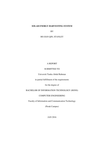
61.4CAMTECH/E/2015-16/Solar Light/1.0PHOTO VOLTAIC EFFECTElectricity can be generated directly from sunlight, by aprocess called photovoltaic effect, which is defined as thegeneration of an electromotive force as a result of theabsorption of ionizing radiation. The photo voltaic effect canbe observed in almost any junction of material that havedifferent electrical characteristics, but the best performance todate has been from solar cells made of Silicon.Fig.1.1: Photo Voltaic effect1.5SOLAR CELL: CONSTRUCTION & WORKINGThe basic building block of a photovoltaic system is theSolar Cell, a semiconductor device having a simple p-njunction and which when exposed to sunlight produces DCelectricity.The solar cell is made up of “Semi-Conductor”materials that are processed to make the device photovoltaic.The solar cell is made of single crystal silicon, polycrystallineand amorphous Silicon with an area of a few sq. centimetersto 200 sq. centimeters and even more.A thin p type silicon wafer is taken through phosphorusdiffusion process and by screen-printing technologyelectrodes are made. The P-N junction of the solar cell givesrise to diode characteristics.November, 2015Handbook on Solar Light System
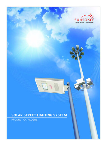
7CAMTECH/E/2015-16/Solar Light/1.0Hence a solar cell is a PN junction device on whichfront and back electrical contacts are screen-printed. A sketchof typical psuedo-square solar cell is shown in fig.1.2 (a) &(b).The side, which has negative polarity, is taken as frontside and that which has positive polarity is taken as backside.The front or Negative side is exposed to sunlight forconduction to take place.Two Tinned copper strips work as terminal leads forinterconnection to other cells. For collection of charge fromthe cell and conduction to terminal leads on negative side,Silver Oxide lines are screen printed horizontally and theseare joined to terminal leads at close spacing (refer fig. 1.2a).These lines cover only 5% of the total area of the cell, so thatthese do not pose any hindrance to the exposure of Sunrays.The back or Positive side is not exposed to sunlight;hence Aluminium is coated on whole surface for betterconductivity (refer fig 1.2b). Aluminium is coated instead ofSilver Oxide as latter is expensive hence not economical.Fig 1.2 (a) Sketch showing front view of typicalPseudo square solar cellHandbook on Solar Light SystemNovember, 2015
8CAMTECH/E/2015-16/Solar Light/1.0Fig 1.2 (b) Sketch showing rear view of typicalPseudo square solar cellFig. 1.2 (c): Solar Cell: Actual viewThe operation of solar cells involves these majorprocesses:i) Absorption of sunlight into semiconductor materialsii) Generation of charge carriers.iii) Separation of ve & -ve charges to different regions ofthe cell to produce e.m.f.November, 2015Handbook on Solar Light System
CAMTECH/E/2015-16/Solar Light/1.01.69SOLAR PHOTO VOLTAIC (SPV) MODULEThe power generated by a single cell is small andtherefore several cells are interconnected in series/parallelcombination to get the required voltage and current. When anumber of solar cells are connected in series to get a specificvoltage the unit so formed is called as Solar Module.Charging batteries is the primary use of SPV module.Therefore normally 36 cells are joined in series to form astandard module, which is capable of charging 12 voltsbattery.A terminal box is provided on the backside of themodule for external connections. A Bypass diode isconnected across ve and –ve in the terminal box. Cathode ofthe diode will be at ve terminal and Anode will be at –veterminal of the module. This diode protects the module cellsfrom overheating due to shadowing of the module or any cellbreakage.Generally the rating of bypass diode is 1.52 times of themaximum current of module. The Repetitive Reverse PeakVoltage Vrrm of the diode should be double the string openvoltage.Standard Capacity/Ratings of SPVThe wattage output of a PV module is rated in termsof wattpeak (Wp) units. The peak watt output power from amodule is defined as the maximum power output that themodule could deliver under standard test conditions (STC).The STC conditions used in a laboratory are 1000 watts per square metre solar radiationintensityAir-mass 1.5 reference spectral distribution25 C ambient temperatureHandbook on Solar Light SystemNovember, 2015
10CAMTECH/E/2015-16/Solar Light/1.0The voltage output of a PV module depends on thenumber of solar cells connected in series inside the module.In India, a crystalline silicon module generally contains 36solar cells connected in series. The module provides a usabledirect current (DC) voltage of about 16.5 V, which isnormally used to charge a 12-V battery.Fig.1.3: Solar ModuleNovember, 2015Handbook on Solar Light System
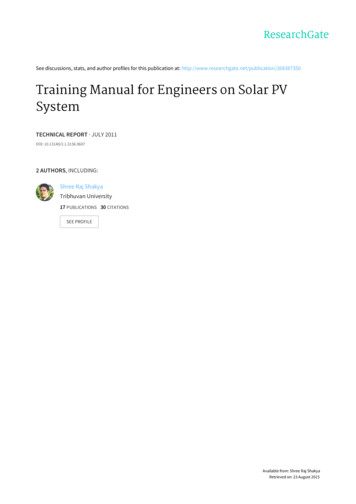
CAMTECH/E/2015-16/Solar Light/1.01.711SOLAR PANELA Solar panel consists of a number of solar modules,which are connected in series and parallel configuration toprovide specific voltage and current to charge a battery. Adiode is connected on the ve terminal of such string inforward bias. This is called Blocking diode.This diode is provided so that in daytime current canflow from module to battery, but at night or in cloudy daycurrent should not flow back from battery to module or fromone string to another string drawing shown in fig 1.4 belowillustrates a Solar panel connected 4 in series and 4 in parallelto charge the battery bank of 48 Volt system.Fig.1.4: Structure of a Solar PanelHandbook on Solar Light SystemNovember, 2015
12CAMTECH/E/2015-16/Solar Light/1.0Solar panels are classified on the basis of the followingpoints :1) Crystalline Silicon (Mono/Poly)2) Different Size or Area of cells3) Type of cells & nos. rcular etc.)4) Power (High/Mid/Low range)1.8CHARGE CONTROLLERCharge controller is the interface between solarpanel/array and battery bank. It protects the battery fromovercharging and moderate charging at finishing end ofcharge of battery bank. Therefore it enhances the life of thebattery bank. It also indicates the charging status of batterieslike battery undercharged, overcharged or deep dischargedthrough LEDs indications. Some switches and MCBs are alsoprovided for manual or accidental cut-off of charging. Thetechnology adopted nowadays for manufacturing solar chargecontroller is MOSFET/IGBT technology.First the controller is connected to battery bank andthen it is connected to solar array/solar module for sensingthe voltage from the module. When the system is put intooperation, the SPV modules start charging the battery bank.Care should be taken that in no case the battery connectionsare removed from the controller terminals when the system isin operation, otherwise SPV voltage may damage the Chargecontroller, since the solar voltage is always higher than thebattery voltage.November, 2015Handbook on Solar Light System
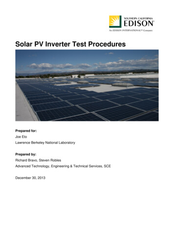
CAMTECH/E/2015-16/Solar Light/1.01.913MOUNTING THE SOLAR MODULESWhile mounting the solar modules, following pointsshould be considered for getting maximum output from thesolar modules: Modules should be oriented south facing to receivemaximum sunlight. The Modules produce more power at low temperature andfull sun.The Solar panels are generally installed in such a waythat they can receive maximum direct sunlight without shadefrom any building/trees nearby falling on them at any part ofthe day.As we know that the Sun rises in the East and sets inthe West as a result of Earth’s rotation around its own axis.Also the Earth revolves around the Sun. Due to these twomovements there is variation in the angle at which the Sun’srays fall on Earth’s surface over a year. At any particularplace on Earth this variation in angle in one year may be up to45 degrees. Considering these facts the following guidelinesare to be kept in mind while installing solar panels:1. Solar panels should be installed South facing in theNorthern hemisphere and North facing in the Southernhemisphere. Since India is in the Northern hemisphere,Solar panels will be installed always- South facing in ourcountry.2. The rule of thumb for fixed (never adjusted) is to set thempointing south at an angle latitude. If it is to beadjusted twice in a year, winter is latitude 15 deg andsummer is latitude - 15 deg.For the angle for "now", point them so that a stickperpendicular to the panel casts no shadow at solar noon(when the sun is at it's peak -- close to noon standardtime).Handbook on Solar Light SystemNovember, 2015
14CAMTECH/E/2015-16/Solar Light/1.0The directions North- South may be found with the helpof Magnetic Compass. The picture given in fig 1.5illustrates this.NorthWestEastSouthFig.1.5: A Solar Panel installation3.Any obstruction (such as tree or building) should beavoided in East, West or South of the place ofinstallation. The following is the criteria:(i) East or West: The distance between solar panel andobstruction should be more than double the height ofobstruction.(ii) South: The distance should be more than half theheight of obstruction.4.The support for the Solar panel need to be a robust oneand should not be accessible to general public. It shouldbe so installed that rainwater, bird dropping, leaves etc.do not accumulate and the top surface can be cleanedeasily.November, 2015Handbook on Solar Light System
CAMTECH/E/2015-16/Solar Light/1.015LatitudeLatitude, usually denoted by the Greek letter phi (φ) gives thelocation of a place on Earth (or other planetary body) north orsouth of the equator. Lines of Latitude are the imaginaryhorizontal lines shown running east-to-west (or west to east)on maps (particularly so in the Mercator projection) that runeither north or south of the equator.Technically, latitude is an angular measurement in degrees(marked with ) ranging from 0 at the equator (low latitude)to 90 at the poles (90 N or 90 for the North Pole and 90 Sor 90 for the South Pole). The latitude is approximately theangle between straight up at the surface (the zenith) and thesun at an equinox.Handbook on Solar Light SystemNovember, 2015
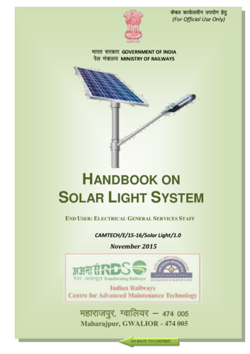
16CAMTECH/E/2015-16/Solar Light/1.0CHAPTER 2STAND-ALONE SOLAR PHOTOVOLTAIC LEDBASED STREET LIGHTING SYSTEMSolar powered outdoor lighting system is ideal forlighting the area in remote locations where the electricity isunavailable or erratic. It can also be used to illuminate thesurroundings of the buildings for security & safety. The streetlightsystem asperRDSOspecificationno.“RDSO/PE/SPEC/0093-2008 (Rev.0), Amend. 3-Sept2010” is based on LED technology which consumes very lowpower. It is a true replacement of normal energy savinglightings.Fig.2.1: Stand Alone LED Solar LightNovember, 2015Handbook on Solar Light System
17CAMTECH/E/2015-16/Solar Light/1.02.1MAIN COMPONENTSThis street lighting system may be used foruninterrupted illumination of the streets, pathways &surroundings of the buildings from dusk-to-dawn for security& safety. This lighting consists of the following components:i.SPV Module to convert solar radiation directly intoelectricity.ii.6 m height MS pole painted with corrosion resistant paintwith necessary accessories.iii.Battery bank to store the electrical energy generated bySPV panel during day time.iv.Charge controller to maintain the battery to the highestpossible State of Charge (SOC) while protecting thebattery from deep discharge (by the loads) or extendedovercharge (by the PV array).v.Blocking diode, preferably a Schottky diode, connectedin series with solar cells and storage battery to keep thebattery from discharging through the cell when there isno output or low output from the solar cell, if such diodeis not provided with the module itself.vi.15 W, 12 V DC LED based luminaire as a light source.vii.Interconnecting wires/cables & hardware.Solar ModuleCharge ControllerBattery BankLED basedLuminaireHandbook on Solar Light SystemNovember, 2015
182.2CAMTECH/E/2015-16/Solar Light/1.0SALIENT FEATURES OF SYSTEM & ITS COMPONENTSi.ii.iii.iv.v.November, 2015The system is designed to have 4 days autonomy (i.e.system will run for 4 consecutive days withoutcharging from the panel).The street light pole should be mounted clear ofvegetation, trees & structure so as to assure that theyare free of shadow throughout day light hours duringeach season of the year.The entire system is designed and built to withstandthe extreme environmental conditions prevailing atsite.All wiring, enclosures and fixtures that are mountedoutdoor are resistant to high humidity conditions,corrosion, insect and dust intrusion.The solar module consists of the following four maincomponents: An assembly of suitablecrystalline silicon solar cells. The solar cells are provided with surface antireflective coating to help to absorb more light inall weather conditions. Toughened, high transmissivity glass in front sideof the module for improved visibility & protectionagainst environmental hazards, such as, rain, hail&stormandweatherproofTEDLAR/POLYSTER back sheet. The transparency of toughened glass used is 91%, when measured in actual sunlight by placingthe glass plate perpendicular to the sun’s raysthrough an air mass of 1.5.inter-connectedHandbook on Solar Light System
19CAMTECH/E/2015-16/Solar Light/1.0 The complete solar module is provided withwater-proof sealing in an anodized aluminiumframe.A bird spike is provided at the highest point of thearray/module structure to avoid bird sitting on thesolar module.Fig.2.3: Solar Module Top Sidevi.The output terminals of the module are provided onthe back of the solar PV module.vii.Terminal block is made of Nylon-6 or equivalentmaterial with weather proof design (IP-65) and have aprovision for opening for replacing the cables.Fig.2.4: Solar Module Back SideHandbook on Solar Light SystemNovember, 2015
20CAMTECH/E/2015-16/Solar Light/1.0viii.All metal equipment cases and frames in the systemshould be well grounded.ix.The Sun is not always available and it is not regular.However, lights are to be fed daily. Therefore powershould be stored in a battery bank. The storage battery bank have enough capacity tokeep the system going on without break downwhen the weather is not favorable for generationof electricity due to cloudy days and rains. LMLA or VRLA batteries are used for thispurpose. LMLA batteries are provided with microporous vent plugs & electrolyte level indicator. Suitable battery Box made of Plastic OR M.Sfabricated is provided to house the battery.Fig.2.5: Battery Boxxi.Charge Controller suitable for both tubular LMLA aswell as VRLA battery is used. This charge controlleruses PWM charging technology. November, 2015When battery discharges more at the end ofautonomy days, in such a situation chargecontroller automatically boost charge the battery.Handbook on Solar Light System
CAMTECH/E/2015-16/Solar Light/1.0 2.321On availability of sun shine (after autonomy days),the night load energy is delivered by the batterythrough the solar charge controller.TECHNICAL DETAILS2.3.1 System Rating:i. Normal system voltage (rated voltage): 12Vdc.ii. System load: 15W LED based luminaire working for12hrs/day. (Dusk-to-Dawn)iii. Battery Autonomy – 4 daysiv. Solar Insolation - 5 peak sun hours/day2.3.2 SPV Modulei.The solar modules are designed to withstand thefollowing environmental conditions normallyencountered at site – Extreme temperature ranging from -10 degree C to 85 degree C. Wind load – 200 km/h. Maximum mean hourly rainfall of 40 mm. Humidity level upto 95%.ii.The conversion efficiency of Solar PV Cells used in themodule is more than 15%.iii.The minimum module rating per LED based street lightsystem is 80Wp (Watt peak)2.3.3 Battery Banki.ii.LMLA or VRLA battery which are specially designedto be charged & discharged frequently and can handleheavy discharges time after time with minimumcharging efficiency of 90%.The minimum capacity of the battery bank shall be12V/75 Ah @ C10.Handbook on Solar Light SystemNovember, 2015
22CAMTECH/E/2015-16/Solar Light/1.02.3.4 Charge Controlleri. Charge controller has automatic dusk-dawn circuit forswitching on/off the street light without manualintervention.ii. It is capable of handling 120% of the module’s ratedcurrent for one hour duration.iii. The controller displays the battery status as followsusing 3 LEDs : Red LED - Low battery Green LED - Battery on charge Yellow LED - Battery fully charged.2.3.5 LED Lamp & fixturesi.Rated Power: 15 W / fixtureii.Light intensity : 1500 Lumens (typical)iii.LED type – White High Powered LED’s 5500-6500 Ktemperatureiv.v.vi.November, 2015LED fixing arrangement - Mounted on metal corePCB fixed to aluminum heat sink.Illumination: More than15 Lux at 1 m from theground (5 m from theLight source).LED Fixture: ABSplastic/Aluminumfixture with acryliccover with IP 55protectionHandbook on Solar Light System
23CAMTECH/E/2015-16/Solar Light/1.0CHAPTER 3MAINTENANCE & TROUBLESHOOTING3.1MAINTENANCESolar panels require virtually no maintenance.However the associated equipment such as batteries andcharge controller are to be maintained in good condition. Once in a month the surface of the panels should bewiped clean with wet rag to remove dust, fallen leaves,bird dropping etc. Only water to be used for cleaning andno other cleaning agent. Once in a month the surface of the LED light fittingshould be wiped clean with wet rag to remove dust etc. General periodical maintenance of lead acid batteryshould be carried out in usual manner and as permaintenance instructions of battery manufacturer.Specially topping up of battery with distilled water asper requirement is essential.3.2PRECAUTIONS AND PREVENTIVE STEPSFor efficient working of SPV system certainprecautions are to be observed as given below:Please ensure that:a)All connections are properly made tight and neat usingthe crimped Red (for ve) and Black (for –ve) wiressupplied by the manufacturer in order to avoid reverseconnection.Handbook on Solar Light SystemNovember, 2015
24CAMTECH/E/2015-16/Solar Light/1.0b)The proper rating of the fuse in the charge controller isprovided.c)The SPV panel is installed facing SOUTH and with thecorrect ‘Angle of tilt’ to get direct sunlight throughoutthe day.d)There is no shadow on any part of the SPV panel at anytime of the day, to get maximum power.e)FIRST the battery, then SPV panel and then load (lightfitting) is connected to charge controller and fordisconnection reverse sequence is adopted.f)Battery terminals are never to be shorted evenmomentarily as shorting will result in HEAVY SPARKAND FIRE. (To avoid the same connect the cable atcharge controller end ‘First’ and then battery end.)g)Never connect the load (light fitting) directly to theSPV panel as it may give higher/lower voltage thanrequired by the load equipment and hence theequipment may be DAMAGED permanently.h)Blocking diode is provided at the array output forprotection against reverse polarity.i)It is NOT HEAT BUT LIGHT that produces energy.So let direct sunlight to fall on the module surfacewithout shades.November, 2015Handbook on Solar Light System
CAMTECH/E/2015-16/Solar Light/1.03.325TROUBLESHOOTINGThe SPV power source is reliable source of electricalenergy. However, there may be rare instances, when the SPVpower source is not able to supply power to the connectedequipment.The diagnosis of the problem in such situations startswith the battery:Check the voltage of the battery. If the voltage of thebattery is correct, there may be problem in the switch /loadMCB is tripped or load fuse is blown off.If none of the above fault is observed then check thespecific gravity of the electrolyte in the secondary cells ofthe battery. There may be two cases:a)If the specific gravity is above the level 1.2(hydrometer reading 1200) value or as specified in themaintenance manual, it implies that the battery is inorder and the problem would be either with the chargecontroller or load.
Handbook on Solar Light System November, 2015 Hence a solar cell is a PN junction device on whi