Transcription
Technical DocumentationDe-Mystifying AutoCAD Plant 3DIsometricsConfiguration Reference1
1 Table of ContentsDe-Mystifying AutoCAD Isometrics . 11Table of Contents . 2Overview . 42Getting Started on AutoCAD Isometrics . 52.1 Isometric Structure.52.2 Creating a company style .52.2.1 Creating a new Style .52.2.2 Testing Isometric Output .63Title Block . 93.1 Title Block Insertion .93.2 Attribute Setup .93.2.1 LDT Setup .93.2.1.1 LDT Overview .93.2.1.2 P&IDs with an LDT .94Themes . 134.1.1 Overview.134.1.2 Default .134.1.3 Override .145Symbols . 165.1 Default Symbol Keys .165.2 Default Symbol Blocks .245.3 Default Symbol Types .335.4 Creating Custom Symbols .345.4.1 Creating a symbol .345.4.2 Create the symbol key reference .355.5 Assigning Custom Symbols .356Advanced Isoconfig.xml Techniques . 386.1 What is the isoconfig.xml .386.1.1 Viewing XML files .386.1.2 XML Notepad 2007 .396.1.3 Foxe .396.1.4 Iso Configuration Editor.406.2 Iso Config Sections .416.2.1 Sections governed by Plant 3D .416.2.1.1 TitleBlockArea .412
6.2.1.2 Skew .426.2.1.3 TableSchemes .436.2.1.4 Title block Attributes .476.2.2 Core Internal Sections .476.2.2.1 Split .476.2.2.2 Data – Controlling Material, Weld, Spool, and Cut List Content .496.2.2.3 Table .526.2.2.4 Titleblock .536.2.2.5 Filters.536.3 Display Settings .546.3.1 Dimensions .546.3.2 Annotations .556.3.2.1 Annotation Leader Styles .566.3.2.2 Annotation Styles .576.3.2.3 Annotation Schemes .576.4 Key Concepts .596.4.1 Model Properties .596.4.2 Line Group Properties .596.4.3 Project/Drawing Properties .596.4.4 Attribute Mapping .607Customization Examples . 617.17.27.37.47.58Modifying Dimension Cutoff .61Modifying Isometric file Names .61Using Lower Case Characters .63Turning Off Coordinates .64Changing the Line Number Callout .65Using AutoCAD Isometrics . 678.1 Production Workflow .678.2 Figures .68Revision History . 713
OverviewAutoCAD Isometrics are a powerful tool that can boost your design production. This paper is going to introduce the coreconcepts of AutoCAD isometrics, and expand on the setup to implement advanced features. We will cover options that areavailable through the project setup dialog, explore creating a title block setup, learn how to test the isometric output,expose features available only through the isoconfig.xml, and document a workflow for managing your isometrics.4
2 Getting Started on AutoCAD Isometrics2.1 Isometric StructureThe isometric structure is centered on styles. Like dimension, annotation, and multi-leader styles, isometric stylesdetermine the color, layout, and structure of your isometrics. The default styles, Check, Final, Spool, and Stress, provide alook at options you want to keep open for your styles.Figure 1 Iso Style Settings2.2 Creating a company style2.2.1 Creating a new StyleTo create a new style, click the Create New Iso Style button in the top left of the Iso Style Setup dialog.Figure 2 Create new Iso Style buttonTypically you create a new style if you want to use a specific style name, or you need to produce isometrics that lookdifferent while preserving the default style options.5
2.2.2 Testing Isometric OutputIn addition to creating a standard company style, you should create a test style. A test style is helpful for identifying modelinformation that would typically not show up in a standard iso style. For example, when troubleshooting models, having astyle that outputs coordinates for every component helps locate items with wrong line numbers.At a minimum your test style should include coordinates for every component. While generating an iso for a typical line,the isometric will be extremely cluttered; however, for instances when a component like a weld has a wrong line number,having the coordinates of that weld will save a lot of time locating the object.First create a new iso style called Test ANSI-B, using the Check ANSI-B style as a template.Figure 3 Create Test ANSI-BClick ok, to save the changes in the project and close the Project Setup dialog. Navigate to the Test ANSI-B folder in yourproject, and open the isoconfig.xml. You will need an XML editor or notepad to modify XML files (For this document I willuse Foxe). You must never edit an xml file while the project setup dialog is open as you will lose any customizations.In Your XML editor, go to Themes Annotations AnnotationSchemes, and copy the FieldWeld ComponentScheme. Rightclick on the same node, and choose Paste After.6
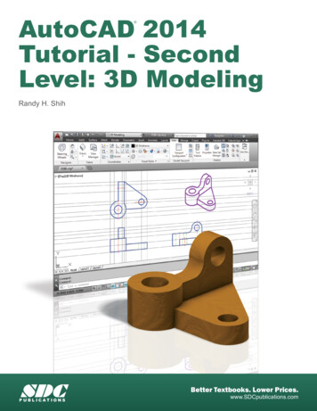
Figure 4 Copying a ComponentSchemeFigure 5 Duplicating a ComponentSchemeAfter duplicating the ComponentScheme, we need to modify it to place coordinates. Change the Name to PlaceCoords,change the Format to “{0}”, Filter to “AnyItem”, Fields to “CO-ORDS”, and Placement to “Along”Save your changes and run a test iso. You should get output similar to this where every component has its coordinateslisted.7
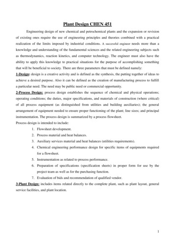
Figure 6 Component CoordinatesFigure 7 Sample Locating CoordinatesIn order to make use of the style, you can use the coordinates to locate objects in the model. For example, there is a weldcalled out with a location of W 73’-0 5/8”, N 63’-2 3/16”, EL -30’-6 3/8”. To locate the weld in the model, make sure you areFigure 8 Line from coordinate to cursorFigure 9 Zoomed View of Located objectusing Architectural units, start the line command and enter -73’-5/8”,63’-2-3/16”,-30’-6-3/8”. By following the line to thecursor to the point in space, we can locate our object.8
3 Title Block3.1 Title Block InsertionSee the isoconfig.xml title block section for details on inserting your own title block. If you don’t modify the isoconfig.xml,follow these steps:1.2.3.4.Insert your title block drawing into the isometric template.Erase the existing Title Block reference.Purge the Title Block block definition.Use the RENAME command to change your company title block name to “Title Block”.3.2 Attribute Setup3.2.1 LDT Setup3.2.1.1LDT OverviewA Line Designation Table (or LDT) allows you to create and modify information external to Plant 3D, but include theinformation on an isometric. Originally, line designation tables were comma delimited (.csv), but now they are ExcelSpreadsheets (.xls, .xlsx). After locating the ldt file, the project setup will read the given file and allow you to locate theposition of the attributes corresponding to the columns in your LDT. Then, you will choose which column includes the linenumber (the unique numeric value) for lookup. When the isometric is created, the file will be scanned for the current linenumber, and the column values for the corresponding row will be inserted into the isometric.3.2.1.2P&IDs with an LDTFor maximum benefit, the P&IDs can be used as a basis for the LDT. When using AutoCAD P&ID for an LDT, you shouldcreate the properties that should be in the LDT at the P&ID Line Group class level.Figure 10 Pipe Line Group PropertiesFor common fields like Equipment To and From, and related P&ID drawings, you can use the PDO Extended Fields pluginwhich will populate the fields based on the drawing data.9
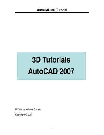
To create the LDT from the P&ID Line Groups for your project, open the Data Manager, select Project Data, then right-clickon Line Group class and choose Export. In the Export Data dialog, check Active Node only and select an appropriatelocation for your spreadsheet.Figure 11 Choosing P&ID Project DataFigure 12 Exporting Pipe Line Group DataFigure 13 Export Active Node OnlyAfter the line group data is exported, you can set up your title block. Go to Setup Title Block in Project Setup.Figure 14 Setup Title BlockFigure 15 Title Block Attributes NavigationIn the title block setup, go to Table Setup.Switch to the LDT Tab, and browse to the Excel spreadsheet you created. You can click view LDT to make sure theinformation was chosen correctly. The Line number column should match the value of the Tag being used for the P3D LineGroup (for example: in the line number column put in column ids (A, B, C, ) not the text of first row of the column).10
Figure 16 P3D Line Group Tag FormatFigure 17 View the LDTAfter selecting the line number column, switch back to the Add Attributes tab to place the attributes from the LDT. Switchthe Attribute category to LDT Attributes, and place the attributes using the format options and selecting the attribute listed.After inserting your attributes, running your iso should give you the properties needed in the correct locations.11
Figure 18 TItleblock with LDT Attributes PlacedFigure 19 Generated Titleblock with LDT Attributes from P&ID12
4 Themes4.1.1 OverviewThemes control how piping objects and annotations get displayed on the isometric. In addition to controlling the layer andcolor of items, themes control how the annotations are used, and what elements belong in annotations. The base themefor isometrics is the Default theme. While the default theme governs general output, Plant 3D provides Override themes tochange the display for specific sets of items. Using a combination of the Default theme and override themes, give Plant 3Disometrics a wide range of customization.Theme Editing is available in part in the Title block setup.Figure 20 Iso Themes Editor4.1.2 DefaultThe Default theme contains the sections that govern aspects of the isometric. Some of the sections are Dimensions,Annotations, BendElbow, Symbols, and Insulation.In the Default Theme tab, we can edit which styles are assigned in the default themes, whether annotations appear,annotation text size, whether dimensions are enabled, and symbol scale.Figure 21 Default Theme Editing13
Figure 22 Default Theme Sections4.1.3 OverrideWhen an isometric is created, the default theme governs the basic item look. However, the isoconfig.xml also containsoverride themes. Override themes allow us to specify special settings for specific set of objects. For example, the SmallBore Piping theme is applied to objects that can be selected using the SmallBorePiping filter (see the Filters section).Figure 23 Small Bore Piping ThemeWithin the Small Bore Piping theme, we have Dimension, Annotations, and Symbols sections. For all of these sections, wecan modify settings in the title block setup under themes.The override themes tab allows us to control similar options for override themes. However, we can’t modify which stylesare used, but we can modify layers separately. While these settings apply for all override themes, by examining the xml forthe override themes, we see more of the options that are available (especially the continuation theme).14
Figure 24 Override Theme EditingFigure 25 Continuation Theme XML15
5 SymbolsLike a P&ID, isometrics are composed of symbols. The program includes a default list of symbols. In order to apply asymbol to a specific part, each symbol is assigned a symbol skey. While a symbol key indicates what a component’srepresentation is on an isometric, the type tells the program how other component data should be applied. This chapterdocuments the currently available symbol keys, the currently used types, and how to create and apply a new customsymbol.5.1 Default Symbol KeysWhile a comprehensive symbol list is not available, a general list of the default values included in each project are below.The list is compiled from the default IsoSkeyAcadBlockMap.xml.SymbolSKEYBlock NameImageDefault TypeElbowEL?, EB?ElbowELBOWReducing ElbowER?ElbowReducingELBOWBendPB?, BE?BendBENDMitered BendMI?BendMitreBEND180 Elbow ReturnEU?Elbow-180returnELBOW180 Bend ReturnBU?Bend-180returnBENDTeeTE?, TY?TeeTEETee BendBT?TeedBendTEEConcentricReducerRC?, CPBW, CS?,RB?ReducerConcEccentric ReducerRE?, ESBWReducerEccREDUCERCONCENTRICREDUCERECCENTRIC16
SymbolSKEYBlock NameImageDefault TypeGasketGASKGasketFilter StrainerFI?Filter-StrainerFILTERAngle UN?Union1UNIONCouplingCO?CouplingCOUPLINGScrewed lingCSCPCoupling-CompressionCapKABWCapCAPScrewed CapKASC, KASW, KAGL,KAPFScrewedCapCAPClamped CapKASC, KASWClampedCapCAPNon-catalog IC17
SymbolSKEYBlock NameImageDefault TypeNippleBSNB?NippleBSOrifice PlateOP, OMPONENTMale Blanking PlugBMMaleBlankingPlugMISCCOMPONENTOpen e NTPipe BlockPFPipeBlockTrapTI?TrapMale to MaleAdapterADMMM M AdaptMale to FemaleAdapterADMFM F AdaptGeneral OletSKSW, TH?,WTBWOlet1OLETHalf-Coupling OletHC?Olet-Half CouplingOLETLatroletLA?Latrolet1OLETFerrule FlaredFE?Ferrule-FlaredCOUPLING18
SymbolSKEYBlock NameImageDefault TypeFlangeFLSO, FOSO, FLSI,FLBL, FLSW, FLRCFlangeFLANGEWeld Neck FlangeFLWN, FOWNFlangeWNFLANGEFitting FlangeFLFL, FLLBFittingFlangeFLANGEStub EndFLSEStub-EndLined FlangeFLGMFlange-LinedFLANGEScrewed FlangeFLGL, FLPF, FLSCFlangeScrewedFLANGEClamped FlangeFLCLClampedFlangeFLANGEFilter with OffsetFO?Filter-OffsetFILTER3 Way ValveV3?3WayValveVALVE-3WAY4 Way ValveV4?4WayValveVALVE-4WAYAngle ValveAR?, CAFL, RA?,AV?ValveAngleVALVE-ANGLEBall ValveVB?BallValveVALVEButterfly ValveVY?ButterflyValveVALVEButterfly Valve 2ZB?ButterflyValve1VALVECheck ValveCK?CheckValve-Alt1VALVELAPJOINTSTUBEND19
SymbolSKEYBlock NameImageDefault TypeSwing Check ValveVC?CheckValveArrowedVALVEDiaphragm ValveVD?Diaphragm ValveVALVEGate ValveVT?, VV?, CV?,VS?, VP?, VR?GateValveVALVEGlobe ValveVG?GlobeValveVALVENeedle ValveNV?NeedleValveVALVEExpansion BellowsEX?ExpanBellowsHand Operator01SP, 05SPOperator Hand1Spring Operator02SPOperator SpringLever Operator03SPOperator LeverDiaphragmOperator04SP, 13SPOperator DiaphragmOperator Hand 206SPOperator Hand2Plug Operator07SPOperator PlugSlide Operator08SPOperator SlideOperator Alt 109SPOperator Alt1Operator Alt 210SPOperator Alt220
SymbolSKEYBlock NameImageDefault TypeOperator Alt 311SPOperator Alt3Operator Alt 412SPOperator Alt4Operator Alt 514SPOperator Alt5Operator Alt 615SPOperator Alt6SupportSUPPSupportSUPPORTGeneral RGSupport-SpringSUPPORTDummy 1SUPPORTSkidSKIDSupport-SKIDSUPPORTSupport onSupportPSIGSupport-SecondaryPipe entConnectionEND-CONNECTIONEQUIPMENTEndEquipment21
SymbolSKEYBlock NameImageDefault TypeTap ConnectionTAP-CONNECTIONEndTappingSplit MarkISO-SPLIT-POINTSplitMarkInstrument TeeITFLInstrument-TeeINSTRUMENTInline InstrumentII?Instrument-InlineINSTRUMENTFlow ArrowFLOWFlowArrowFLOW-ARROWFloor SymbolFLORFloor SymbolFLOOR-SYMBOLReinforcement PadRPADReinforcementPadWhere the SKEY uses ?, you may specify an end type skey from the end types list. This list is also stored in theIsoSkeyAcadBlockMap.xml and is configurable. A reference to what end code abbreviations mean may be retrieved byusing the PLANTENDCODES command to display the end code list.End TypeSKEYBlockField WeldWF, WSFieldWeldWeldWW, SO, WN, SJWeldButtweldBW, BVButtweldSocket 2
Flanged FittingFLFittingFlangeFlared EndFA, TCFlareEndClampedCLClampOperators are related to valves using the following settings from the IsoSkeyAcadBlockMap.xmlSpindle SkeyValve Skey01SPAV?, VV?, VD?, VG?, VT?,V3?, V4?,08SPVS?03SPVB?, VY?, VK?07SPVP?13SPCV?02SPVR?10SPZB?23
5.2 Default Symbol BlocksSupplementing the skey/symbol information is a list of the default blocks. Browsing this list will show you want parametersare used in each block. Block images are linked from their symbol keys above. Below is a list of blocks that are typical oftheir category.CategoryBlockName2 Port torsOperator Hand1SupportsSupport24
The list below is of the more complicated blocks that demonstrate unique features. For parameter details see FAQ: How doI create a custom Iso symbol?.Figure 26 ElbowFigure 27 ElbowReducingFigure 28 BendFigure 29 BendMitre25
Figure 30 Elbow-180returnFigure 31 Bend-180returnFigure 32 TeeFigure 33 TeedBend26
Figure 34 ReducerConcFigure 35 ReducerEccFigure 36 GasketFigure 37 Filter-Strainer27
Figure 38 Filter-AngleFigure 39 CrossFigure 40 CapFigure 41 ScrewedCap28
Figure 42 NipoletFigure 43 FlangeFigure 44 FlangeWNFigure 45 FittingFlange29
Figure 46 Flange-LinedFigure 47 FlangeScrewedFigure 48 ClampedFlangeFigure 49 3WayValve30
Figure 50 4WayValveFigure 51 ValveAngleFigure 52 BallValveFigure 53 CheckValve-Alt131
Figure 54 Operator Hand1Figure 55 Support 32
5.3 Default Symbol TypesAlong with recognizing which symbol should be used, you need to know which types are available. The type controls whatinformation gets included on the isometric. For example, certain objects like caps get a callout indicating that it closes theend of the pipe line. Any symbol that should receive the closing callout should use the CAP type with whichever symbol keyis appropriate. In some scenarios, you will need to test a couple different types in order to get the exact look you need foryour isometric. The types below were extracted from the catalogs, so the list may not be comprehensive. E-ANGLE33
5.4 Creating Custom SymbolsOne symbol people frequently want to show is a flow meter sometimes shown as thesymbol from the P&IDs. Tocreate the symbol you will need to decide which default symbol to use as a template, save it as a new block, create areference to the block in our Isoskeyacadblockmap.xml, and apply the new skey in a model.5.4.1 Creating a symbolRather than creating new symbols on the fly, the best approach is to use an existing symbol that is similar to the one beingcreated. You should choose a symbol that has the same number of ports and similar behavior. For example, if your symbolis flow dependent, start by using the check valve symbol. Project symbols are stored in the Isometric folder in the drawingcalled IsoSymbolStyles.dwg. These symbols can be applied to any style in the project.After opening the IsoSymbolStyles.dwg, enter BEDIT at the command line to launch the block editor. Locate CheckValveAlt1 and click OK.Create a new block called FlowMeter by using Save Block As.Replace the line work with our boxed M. Also, move the Port1 and Port2 point parameters to the midpoint of your square ifneeded. The image below uses text height 1, so the box is 1.5 x 1.5 units. Use lines instead of text, since text does notalways orient itself correctly inside of blocks.34
Save and close the FlowMeter block and IsoSymbolStyles.dwg.5.4.2 Create the symbol key referenceOpen IsoSkeyAcadBlockMap.xml in your project’s Isometric folder. Scroll down to the section title Instrument symbols, andadd this line: SkeyMap SKEY “FM?” AcadBlock ”FlowMeter”/ This line indicates that when a model component has a symbol key that starts with FM and uses any valid endtype, theFlowMeter block should be inserted in the isometric. If you use an SKEY that’s not in this mapping table, isometrics willattempt to find a block with the same name as the SKEY in the isosymbolstyles drawing.Save your changes to the IsoSkeyAcadBlockMap.xml5.5 Assigning Custom SymbolsBelow is a ball valve from a model. The Content Iso Symbol Definition is filled out with the SKEY and the TYPE. Notice thatthere is not a space after the comma separating the two items. Including a space will not allow the correct symbol key tobe used. The order, however, does not matter, so you can put the TYPE or the SKEY first. To test the symbol key, fill out theskey so it says, “FMFL”.35
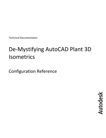
The produced iso has an operator since we tested it on a ball valve. Ifwe were to use a custom flow meter, the operator would not be present.After creating a symbol key, you should apply it to an item in the model and test it before implementing it in a catalog.Once you have verified the skey is drawn correctly and uses the appropriate type, you may add it to the catalog componenton the General Properties tag and the bottom right under Piping Component Properties. Adding it to the catalog will allowthe component to come in with the correct isometric symbol. To add our new symbol key to a catalog, you should use theINSTRUMENT type with our FMFL symbol key.36
Figure 56 Iso Symbol Type and Skey at bottom right37
6 Advanced Isoconfig.xml Techniques6.1 What is the isoconfig.xmlXml stands for eXtensible Markup Language. Although called, a language, it’s better to think of xml as a way of organizinginformation for developers. Xml is closer to customizable database format than a programming language. For furtherinformation on using XML please read: http://www.w3schools.com/xml/xml whatis.aspBecause we are not working with web files, understanding html and JavaScript is not a prerequisite for a successfulisometric implementation. Information within xml is grouped within tags by including sub-tags, and/or attributes. Thecontents and types of tags are completely definable by the developer. The xml follows a loose structure dictated here:http://www.w3schools.com/xml/xml tree.asp. To summarize, xml documents have a namespace declaration in openingand closing brackets, and then a root element which encapsulates the rest of the child elements. In short, xml is organizedin a tree hierarchy with elements indicated by brackets. Applying the structure to the isoconfig.xml, our root element is theelement IsoconfigDefinition.Xml definitions:Tag – a value surrounded in brackets, i.e. Tag Closed Tags – an element (tag) is closed with a slash “/” - Tag/ . Elements with children are started with an open tag, Tag and clo
Themes control how piping objects and annotations get displayed on the isometric. In addition to controlling the layer and color of items, themes control how the annotations are used, and what elements belong in annotat