Transcription
Plant Design CHEN 451Engineering design of new chemical and petrochemical plants and the expansion or revisionof existing ones require the use of engineering principles and theories combined with a practicalrealization of the limits imposed by industrial conditions. A successful engineer needs more than aknowledge and understanding of the fundamental sciences and the related engineering subjects suchas thermodynamics, reaction kinetics, and computer technology. The engineer must also have theability to apply this knowledge to practical situations for the purpose of accomplishing somethingthat will be beneficial to society. There are three parameters that must be defined namely:1-Design: design is a creative activity and is defined as the synthesis, the putting together of ideas toachieve a desired purpose. Also it can be defined as the creation of manufacturing process to fulfilla particular need. The need may be public need or commercial opportunity.2-Process Design: process design establishes the sequence of chemical and physical operations;operating conditions; the duties, major specifications, and materials of construction (where critical)of all process equipment (as distinguished from utilities and building auxiliaries); the generalarrangement of equipment needed to ensure proper functioning of the plant; line sizes; and principalinstrumentation. The process design is summarized by a process flowsheet.Process design is intended to include:1. Flowsheet development.2. Process material and heat balances.3. Auxiliary services material and heat balances (utilities requirements).4. Chemical engineering performance design for specific items of equipments requiredfor a flowsheet.5. Instrumentation as related to process performance.6. Preparation of specifications (specification sheets) in proper form for use by theproject team as well as for the purchasing function.7. Evaluation of bids and recommendation of qualified vendor.3-Plant Design: includes items related directly to the complete plant, such as plant layout, generalservice facilities, and plant location.1
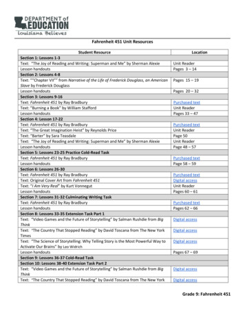
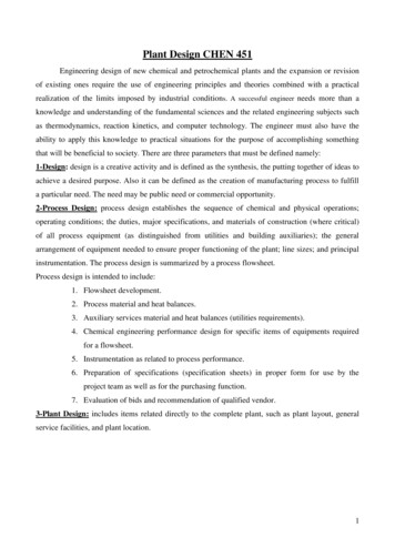
Design Development Stages:The stages in the development of a design, from the initial identification of the objectives tothe final design are shown in Fig.(1).Fig.(1) The design process.(I) The Design Objectives (The Need)Engineering projects can be divided into three types:A. New process development.B. New production capacity to meet growing sales.C. Modification and addition to existing plant.In the design of a chemical process the need is the public need for the product, the commercialopportunity as foreseen by the sales and marketing organization.(II) Setting The Design Basis (Data Collection)The most important step in starting a process design is translating the customer need intoa design basis. The design basis is a more precise statement of the problem that is to be solved. It willnormally include the production rate and purity specifications of the main product, together withinformation on constraints that will influence the design, such as:1. Information on possible processes and the system of units to be used.2. The national, local or company design codes that must be followed.3. Details of raw materials that are available.4. Information on potential sites where the plant might be located, including climate data, seismicconditions, and infrastructure availability.5. Information on the conditions, availability, and price of utility services such as fuel (gas), steam,cooling water, process air, process water, and electricity, that will be needed to run the process.2
(III) Generation of Possible Design Concepts (Solutions)It is the creative part of the design process. This part is concerned with the generation ofpossible solutions for analysis, evaluation, and selection (ways of meeting objective problems).Source of solutions:a- Past experiences.b- Tried and tested methods.(IV) Build Performance Model and Fitness TestingWhen design alternatives are suggested, they must be tested for fitness of purpose. In otherwords, the design engineer must determine how well each design concept meets the identified need.In the field of chemical engineering, it is usually prohibitively expensive to build several designs tofind out which one works best (a practice known as ‘‘prototyping’’ which is common in otherengineering disciplines). Instead, the design engineer builds a mathematical model of the process,usually in the form of computer simulations of the process, reactors, and other key equipment. Insome cases, the performance model may include a pilot plant or other facility for predicting plantperformance and collecting the necessary design data.The design engineer must assemble all of the information needed to model the process so asto predict its performance against the identified objectives. For process design this will includeinformation on possible processes, equipment performance, and physical property dataIf the necessary design data or models do not exist, then research and development work isneeded to collect the data and build new models. Once the data has been collected and a workingmodel of the process has been established, then the design engineer can begin to determineequipment sizes and costs. At this stage it will become obvious that some designs are uneconomicaland they can be rejected without further analysis. From this step a few candidate designs that meetthe customer objective are identified.(V) Economic Evaluation, Optimization, and SelectionOnce the designer has identified a few candidate designs that meet the customer objective,then the process of design selection can begin. The primary criterion for design selection is usuallyeconomic performance, although factors such as safety and environmental impact may also playa strong role. The economic evaluation usually entails analyzing the capital and operating costs ofthe process to determine the return on investment (R.O.I).The economic analysis of the product or process can also be used to optimize the design.Every design will have several possible variants that make economic sense under certain conditions.For example, the extent of process heat recovery is a tradeoff between the cost of energy and the costof heat exchangers (usually expressed as a cost of heat exchange area). In regions where energy costs3
are high, designs that use a lot of heat exchange surface to maximize recovery of waste heat for reusein the process will be attractive. In regions where energy costs are low, it may be more economical toburn more fuel and reduce the capital cost of the plant.When all of the candidate designs have been optimized, the best design can be selected. Veryoften, the design engineer will find that several designs have very close economic performance, inwhich case the safest design or that which has the best commercial track record will be chosen. Atthe selection stage an experienced engineer will also look carefully at the candidate designs to makesure that they are safe, operable, and reliable, and to ensure that no significant costs have beenoverlooked.(VI) Detailed Design and Equipment SelectionHere the detailed specifications of equipment such as vessels, exchangers, pumps, andinstruments are determined. During the detailed design stage there may still be some changes to thedesign, and there will certainly be ongoing optimization as a better idea of the project cost structureis developed. The detailed design decisions tend to focus mainly on equipment selection though,rather than on changes to the flowsheet. For example, the design engineer may need to decidewhether to use a U-tube or a floating-head exchanger, or whether to use trays or packing for adistillation column.(VII) Procurement, Construction, and OperationWhen the details of the design have been finalized, the equipment can be purchased and theplant can be built. Procurement and construction are usually carried out by an EPC firm(Engineering, Procurement, and Construction) unless the project is very small. Because they work onmany different projects each year, the EPC firms are able to place bulk orders for items such aspiping, wire, valves, etc., and can use their purchasing power to get discounts on most equipment.The EPC companies also have a great deal of experience in field construction, inspection, testing,and equipment installation. They can therefore normally contract to build a plant for a client cheaper(and usually also quicker) than the client could build it on its own. Finally, once the plant is built andreadied for startup, it can begin operation. The design engineer will often then be called upon tohelp resolve any startup issues and teething problems with the new plant.4
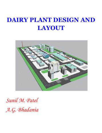
Design ConstraintsWhen considering possible ways of achieving the objective the designer will be constrainedby many factors which are called the design constraints.Design constraints are divided into two types Fig.(2):A. Internal constraints: over which the designer has some control.B. External constraints: fixed, invariable.What is meant by design constraints? What are the different types? Give examples?What are the main items that should be included in the process design?Draw a block diagram showing the main steps involved in the development of a designprocess?Fig.(2) Design constraints.5
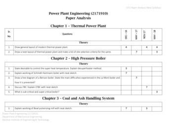
Flow-sheeting (special language conveying information)Process design normally starts with a process scheme (flowsheet). The flowsheet is the keydocument or road map in process design. It's a diagrammatic model of the process describe theprocess steps in a proper sequence using symbols to represent the various components (equipment,lines, and control instrumentation) that make up the unit.The Flow-sheet Importance Shows the arrangement of the equipment selected to carry out the process. Shows the streams concentrations, flow rates & compositions. Shows the operating conditions. During plant start up and subsequent operation, the flow sheet from a basis for comparison ofoperating performance with design. It's also used by operating personnel for the preparationof operating manual and operator training.Flowsheet Presentation1- Block diagram Represent the process in a simplified form. No details involved. Don’t describe how a given step will be achieved.When is it used? In survey studies. Process proposal for packaged steps. Talk out a processing idea.Fig.(3) Block diagram.6
2- Pictorial Flow SheetThe equipments are normally drawn in a stylized pictorial form. For tender documents orcompany brochures actual scale drawing of the equipment are sometimes used.Types of pictorial flow-sheetsa) Process Flow Diagram (PFD)A PFD is a simplified flow diagram of a single process unit, a utility unit, a complete processmodule. The purpose of a PFD is to provide a preliminary understanding of the process systemindicating only the main items of equipment, the main pipelines and the essential instruments,switches and control valves.A PFD also indicates operating variables, such as mass flow, temperatures and pressures, whichare tabulated at various points in the system.The PFD is a document containing information on: Process conditions and physical data of the main process streams. Main process equipment with design data. Main Process lines. Mass (material) balance. Heat balance (if applicable).NOTE: If the PFD doesn’t contain any data about the flow rates, it is called a qualitative flowsheet,while if the flow rates are involved the PFD is called a combined flowsheet in which qualitativeinformation and quantitative data are combined on the basis of one flowsheet.b) Piping and Instrumentation Diagram (P & ID) (mechanical flow diagram)A P&ID diagram shows the arrangement of the process equipment, piping, pumps, instruments,valves and other fittings. It should include: All process equipment identified by an equipment number. All pipes identified by a line size, material code and line number. All valves with an identified size and number. Fittings. All pumps identified by a suitable code number. All control loops and instruments.c) Utility Flowsheet (Process Engineering Utility Flow Diagram (PEUFD))Used to summarize and detail the interrelationship of utilities such as air, water (various types),steam (various types), heat transfer mediums, process vents and purges, safety relief blow-down,7
etc., to the basic process. The amount of detail is often too great to combine on other sheets, soseparate sheets are prepared.The PEUFD is a document containing information on: Main distribution or arrangement of each individual utility system, expect electrical systems.PEUFD Function:A typical process uses utilities such as water, air and electric power. Water may be used either in theprocess, or for cooling and/or production of steam. Air may also be used in the process or forinstrument applications. Electric power of course is typically used at various points in the processand throughout the site.It is always useful to develop diagrams that show the flow and utilization of each utility. An exampleof a water balance/utility diagram is shown below.The PEUFD shall state characteristics and consumption figures of the particular utility concerned,cooling water, fire water, drinking water, steam, plant air, instrument air, fuel oil/gas, inert gas andsimilar utilities.d) Process Safeguarding Flow Diagram (PSFD)The PSFD is a document highlighting information on: Types and levels of protection offered by the devices installed and their inter relation todemonstrate the plant’s safety.The P&ID contains all information required for a PSFD; however, the PSFD highlights protection incase of extreme conditions and measures to be taken to safeguard personnel and environment.Note: In general these schemes will only be made for complex installations like offshore processplatforms. For simple applications the information shown on the P&ID is usually sufficient tohighlight safety devices and aspects. What is meant by the following identifications? PFD, P&ID, PEUFD and PSFD State the information you can get from the following schemes: PFD, P&ID, PEUFD andPSFD?8
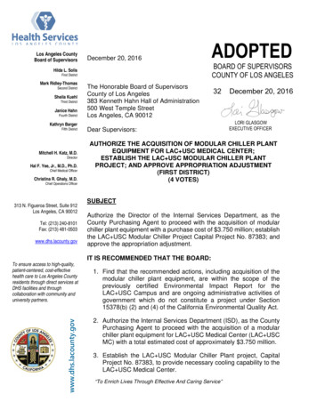
Fig.(4) PFD [Qualitative flow diagram for the manufacture of nitric acid by the ammonia-oxidation process].Fig.(5) PFD [Combined flow diagram for the manufacture of nitric acid by the ammonia-oxidation process].9
Fig.(6) Process and Instrument Diagram (P&ID)Fig.(7) Typical utility flowdiagram.10
Fig.(8) Engineering P&ID flowsheet11
Flowsheet SymbolsTo reduce detailed written descriptions on flowsheets, it is usual practice to develop or adopta set of symbols and codes which suit the purpose. Many symbols are pictorial which is helpful inrepresenting process as well as control and mechanical operations. See Fig.(9)Line Symbols and DesignationThe two types of lines on a flowsheet are (1) those representing outlines and details ofequipment, instruments, etc., and (2) those representing pipe carrying process or utility liquids,solids, or vapors and electrical or instrument connections. The latter must be distinguished amongthemselves as suggested by Figure (10).The usual complete line designation contains the following: (1) line size (nominal); (2)material cod; (3) sequence number; and (4) materials of construction.Examples: 2"-CL6-CS403"-CL6a-CS40Equipment DesignationEquipment code designations can be developed to suit the particular process, or as iscustomary a master coding can be established and followed for all projects. A suggested designationlist (not all inclusive for all processes) for the usual process plant equipment is given in Table (1).The various items are usually numbered by type and in process flow order as set forth on theflowsheets. For example:Item codeDesignationS-1First separator in a processS-2Second separator in a processC-1First compressor in a process12
Fig. (9.a) Flowsheet symbols.13
Fig. (9.b) Flowsheet symbols contd.14
Fig.(10) piping and connection symbols from different sources(Line symbols)Table 115
Fundamentals of Material BalanceMaterial balances are the basis of process designMaterial balance is also useful tool for the following:1. The study of the plant operation & troubleshooting.2. Check performance against design.3. Check the instrument calibration.Conservation of Mass:The general mass balance equation:Input – output generation – consumption AccumulationFor steady-state non reactive system:Input Output[Number of equations Number of components]For steady-state reactive system:Input – output generation – consumption 0.016
Some Important Parameters for Reactive System:Limiting Reactant:It's the reactant that would be completely consumed if the reaction proceeded to completion.As it disappears the reaction stops. It's also called the rate determining component since itsconcentration determines the reaction rate. All other reactants must either be fed in stoichiometricproportion to the limiting reactant (the feed rates are in the ratio of the stoichiometeric coefficients)or in excess of the limiting reactant (in greater than stoichiometric proportion to it).Stoichometry:It's used to balance chemical reaction equations. The stoichiometric equation for a chemicalreaction states the number of molecules of the reactants and products that take part, from which thequantities can be calculated.For simple reactions can be done by inspection. بمجرد النظر For complex reactions take a base of 1 mole of one component and make an atomic balance oneach element (It's better to choose one with many atoms as possible).Fractional Conversion:It's the ratio of amount reacted to amount fed. The fractional conversions of different reactantsare generally different unless the reactants are fed in stoichiometric proportion.Fractional Conversion Note: In case of reaction process with recycling of unreacted reactants, there are 2 types ofconversion:a- Single pass conversion b- Overall conversion17
The overall conversion should be single pass conversion [one of the recycle functions is tomaximize conversion]Selectivity:It's a measure of the efficiency of the reactor in converting reagent to the desired product. It isthe fraction of the reacted material that was converted into the desired product. If no byproducts areformed, then the selectivity is 100%.Selectivity Yield:It's a measure of the performance of a reactor or a plant.There are 2 types of yield:a- Reaction yield (Chemical yield)Reaction yield ConversionSelectivity Where moles reagent converted includes that consumed in both main & side reactions.Note: Reaction yield conversion when there is no side reactions take place.b- Plant YieldPlant yield is a measure of the overall performance of the plant and includes all chemical &physical losses (during separation process).Plant Yield Stoichiometric factor theoretical moles of reagent required per moles of product produced in thereaction balanced equation.18
Excess:A reagent may be supplied in excess to promote the desired reaction to:1- Maximize the use of an expensive reagent.2- Ensure complete reaction of a reagent, as in combustion.% Excess 100 100Note: Excess component actual feed Theoretical feed (1 fraction excess)Tie Component:If one component passes unchanged through a process unit (inert component), it can be used totie the inlet & outlet compositions. Since its amount is the same in input & output so the total amountof input & output can be calculated if their compositions are known. Example: Nitrogen incombustion reactions.Bypass:A flow stream may be divided and some part diverted (bypassed) around some units. Thisprocedure is often used to control stream composition or temperature.Recycle:It's used to send unused raw materials emerging from a process unit back to the unit. Overallsystem balances are usually (but not always) convenient starting points for analyzing process withrecycle.Purge:A stream that's withdrawn from a process when a species enters in the process feed and iscompletely recycled. If this species weren't removed in the purge, it would keep accumulating in theprocess system and eventually lead to shutdown.19
Purge stream used to: Maintain the steady state conditions in the system Prevent the accumulation of inert or undesired materials [To rid the process of the undesiredmaterial]Combustion Reactions:Excess air is used in combustion to:1- Ensure complete combustion.2- Minimize Co & smoke formation.Note: % excess air % excess oxygenAir 79% N2 21% O2 by molesAir 77% N2 23% O2 by massThe calculated amount of excess air doesn't depend on how much material is actually burnedbut what can be burned. Excess O2 (air) is calculated from the complete combustion equation, i.e.based on conversion of all C CO2, S SO2 & H H2O.20
Important Note: Using to much excess air means that more air will be heated (i.e. high energylosses). While if %excess air is less than 3, flame impingement to the furnace tubes.Expressing the Composition of a Material Stream: Mass fraction component mass / total stream mass Mole fraction component moles / total stream moles Volume fraction component volume / total stream volumeNote: volume fraction mole fraction for gases up to 25 bar.For traces quantities:ppmpart per millionppbpart per billionNote: UK billion 1012 while USA billion 109Choice of a basis for Calculations:A basis of calculation for a process is an amount or flow rate of one of the process streams,preferably that stream with known composition. The basis may be a period of time for example,hours, or a given mass of material.1- For continuous process (production or feed rate is given as kg/hr, ton/day, . etc) Basisis1 hr or 1 operating day (unit of Time)2- For batch process (production or feed rate is given as kg/batch , ton/batch, etc ) Basisis 1 batch.3- If the flow rates are not given For composition given as mass fraction (in case of liquids or solids), basis is often 1 or 100lbm or kg. For composition given as mole fraction (in case of gases), basis is often 1 or 100 lb mol orkmol.Note: It's important that your basis be indicated near the beginning of the problem.21
Choice of thesystem boundarySystem boundary: The part of the process being considered.The system chosen must have a degree of freedom 0.0 in order to be able to be solved (i.e. No. ofequations No. of unknowns).Note: For any reactive system, the following parameters should be defined:1- Yield or conversion.2- % Excess if present.3- Concentrations (strength) of reactants & products streams.4- Recovery.Recover General Procedures for Material Balance Problems:1- Draw a block diagram of the process.2- List all the available data.3- List all the information required from the balance.4- Write out all the chemical reactions involved.5- Decide the basis of your calculations.6- Decide the system boundary.22
Fundamentals of Heat BalanceHeat balance is a special case of energy balance. Target of heat balance depends on the type ofthe system.1. Reactive System:Heat balance is important to:1- Calculate the rate of heat addition or removal from the system to maintain the reactionmixture at the desired temperature to ensure certain degree of conversion.2- Calculate the flow rates of heating or cooling utilities required.3- Calculate the heat transfer area required for heating or cooling.a- Calculation of rate of heat removal / addition:i-For continuous system:Q n : Molar reaction rate of the limiting reactant (mol/ hr) n feed single pass conversionStandard specific heat of reaction at 298K (kJ/mol) : Component stoichiometric coefficient in the balanced equation.: Component standard heat of formation (kJ/mol).Note: For a reaction A 2 B C -240 kJ/molThat means that the heat released from the reaction of 1 mole of A with 2 mole of B to produce 1mole of C 240 kJ. If 100 mole of B reacts with 50 mole of A the heat produced 100/2 240 or 50/1 240 1200 kJ.23
For exothermic reaction:Cooling is mustCalculate flow rate of cooling water:Q m Cpm : cooling water mass flow rate4.2 kJ/kg.KCp1 Btu/lbm. F: Tout - Tin 10 15 C (if not given)Cooling water pump capacity (pump volumetric flowrate) can be calculated:Capacity of the cooling water pump (m3/hr, Gpm orLpm)For endothermic reaction:Heating is mustCalculate the steam consumption: If steam enters as saturated vapor & exit assaturated liquidQ ms λsms : Steam mass flow rate (kg/hr)λs: Latent heat of vaporization (kj/kg) (from steam tables) If steam enters as super heated vapor & exit as sub-cooled liquid:Q ms Cpv ms λs ms CpL T steam – T boilingCpv: Steam specific heat (kJ/kg.K) T boiling – T outCpL: water specific heat (kJ/kg.K)Note: you can calculate steam consumption regardless type of phase change:Q ms [ in ]If heating is done by using oil: Mass flow rate of the heating oil:Q m Cpm : oil mass flow rate.24
ii-For batch system:Q Reaction time cycle time (if not given)Specific heat of reactionn: no of moles reacted form the limiting reactant per cyclen n fed per cycle conversionn fed per cycle No. of cycles Important note:To calculateat any temperature: R A T0 [ - 1] T02 [ - 1] T03 [ -1] [], A, B, C & D are constants (from thermodynamic tables)A & so for B, C & Db- Calculation of Heat Transfer Area Required for Heating or Cooling:Q UAU: Overall heat transfer coefficient (W/m2.K).A: Heat transfer area (m2).: Temperature difference (K or C).25
Note: ΔT is calculated based on counter current flow unless otherwise is given.AReactor with jacketReactor with coilHeat ExchangerA Jacket areaA coil areaA tubes area π d0 L N π d0 LCoil length (L) can Numberoftubes(N)canbebe calculated if d0 calculated if the tube dims. areis knownknown (L & d0)2. Non-Reactive System:This includes all the systems in which heat transfer takes place without chemical reaction.Q in this case depends on the system.a. For Heaters/Coolers:Q m CpOnly sensible heat (no phase change)b. For Vaporizers:General heat load equation:Q m CpL (T boiling – T feed) m λ m CpV (Tout - T boiling)If the outlet is saturated vapor:Q m CpL (T boiling – T feed) m λIf the feed is saturated liquid:Q m λ m CpV (Tout - T boiling)26
If the feed is saturated liquid & the outlet is saturated vapor:Q m λc. For Condenser:Q m λd. For Cooler-Condenser:Q m Cp ΔT m λe. For Evaporators:Q m feed Cp feed (T boiling – T feed) V λ27
Equipment Sizingi.e. Calculation of reactors volume & dimensions.Calculation of storage (holding) tank volumes.1- Batch Reactor: [V reactants fed/cycle V catalyst (if exist)] *% Full 75 if not givenV reactants fed/cycle No of cycles After calculation of the reactor volume, its dimensions can be calculated:Aspect ratio (If not given it can be assumed 5)2- Continuous Reactor:Space time τ Space velocity For gas phase:P n R T (assuming ideal gas behavior P 15 bar)Feed reactants volumetric flow rate.n : Feed reactants molar flow rate.For liquid phase:Note: For mixed phase reaction the volume is calculated based on the gas volume.28
General Procedure for Reactor Design:1) Collect together all the kinetic & thermodynamic data on the desired reaction and the possibleside reactions (these data are obtained from literature or laboratory & pilot plant test).2) Collect the physical properties required for the design 9 from literature, estimation bylaboratory measurements).3) Identify the controlling step [Kinetic or mass] and choose the suitable reactor type based onthe experience with similar reactions or from the laboratory or pilot plant work.4) Make initial selection of the reactor conditions to give the desired conversion & yield.5) Size the reactor.6) Select a suitable material of construction.7) Make a preliminary mechanical design for the reactor.8) Cost the proposed design (repeat steps 4 8 to optimize the design).Storage (Holding) Tank:Storage tank is used for raw materials & final products.Holding tanks is used in case of batch process.Note: % Tank full 29
Types of DesignsThe methods for carrying out a design project may be divided into the following classifications,depending on the accuracy and detail required:1. Preliminary or quick-estimate designsUsed as a basis for determining whether further work should be done on the proposed process.This type of design is based on approximate process methods, and rough cost estimates are prepared.Few details are included, and the time spent on calculations is kept at a minimum.2. Detailed-estimate designsIn this type of design, the cost and profit potential of an established process is determined bydetailed analysis and calculations. However, exact specifications are not given for the equipment,and drafting-room work is minimized. The following factors should be established within narrowlimits before a detailed-estimate design is developed: Manufacturing process Material and energy balances Temperature and pressure ranges Raw-material and product specifications Yields, reaction rates, and time cycles Materials of construction Utilities requirements Plant sitei.e the above factors should be determined after a preliminary design.3. Firm process designs or detailed designsWhen the detailed-estimate design indicates that the proposed project should be a commercialsuccess, the final step before developing construction plans for the plant is the preparation of a firmprocess design. In this type complete specifications are presented for all components of the plant,without any change in the process flowsheet and accurate costs based on quoted prices are obtained.The firm process design includes blueprints and sufficient information to permit immediatedevelopment of the final plans for constructing the plant.Design Information (literature survey)General information and specific data required to the development of a design project can beobta
Plant Design CHEN 451 . 3-Plant Design: includes items related directly to the complete plant, such as plant layout, general service facilities, and plant location. 2 . C. Modification and addition to existing plant. In the design of a chemical process the ne