Transcription
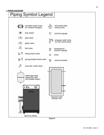
22I. PIPING DIAGRAMSFigure 6LP- 276 REV. 3.28.14
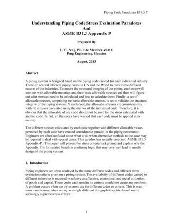
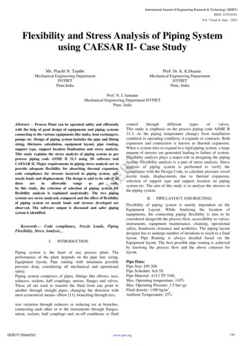
23Figure 7NOTES:1. This drawing is meant to demonstrate system piping concept only. Installer is responsible for all equipment and detailing required by local codes.2. Boiler circulator(s) must be rated for open loop applications. Do not use cast-iron circulators.3. Boiler circulator(s) operate continuously.4. The minimum pipe size for connecting to a water storage tank is 1 ½”.5. The minimum pipe size for connecting the boiler is 1 ½” for the Mod Con 300 VWH and 2” for the 500 and 850 models.6. All pumps are shown with isolation flanges or full port ball valves for isolation. The alternative is standard flanges with full port ball valves and aseparate flow check valve.7. Install a minimum of 12 diameters of straight pipe upstream of all circulators and check valves.8. Install a vacuum relief valve in accordance with local code requirements.9. Multiple boilers and storage tanks shall be installed with reverse return piping (as shown).10. Mixing valves are recommended on all tanks if hot water temperature is above 119oF.11. Expansion tank must be rated for use with potable water.12. Use either indirect/tank sensor or system/pipe sensor mounted on common return to the boiler.13. Aquastat or system/pipe sensor connects to DHW sensor input on boiler.LP- 276 REV. 3.28.14
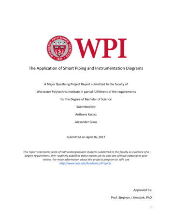
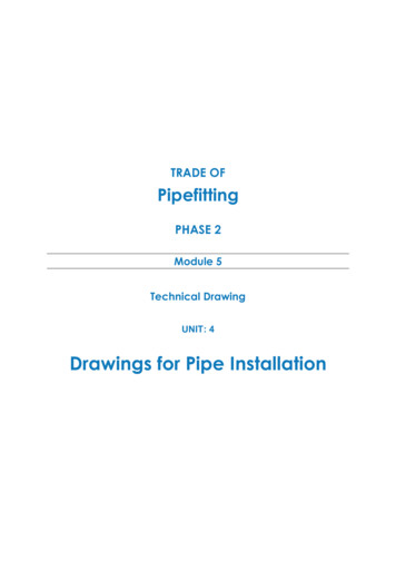
24Figure 8NOTES:1. This drawing is meant to demonstrate system piping concept only. Installer is responsible for all equipment and detailing required by local codes.2. Boiler circulator(s) must be rated for open loop applications. Do not use cast-iron circulators.3. Boiler circulator(s) operate continuously.4. The minimum pipe size for connecting to a water storage tank is 1 ½”.5. The minimum pipe size for connecting the boiler is 1 ½” for the Mod Con 300 VWH and 2” for the 500 and 850 models.6. All pumps are shown with isolation flanges or full port ball valves for isolation. The alternative is standard flanges with full port ball valves and aseparate flow check valve.7. Install a minimum of 12 diameters of straight pipe upstream of all circulators and check valves.8. Install a vacuum relief valve in accordance with local code requirements.9. Multiple boilers and storage tanks shall be installed with reverse return piping (as shown).10. Mixing valves are recommended on all tanks if hot water temperature is above 119oF.11. Expansion tank must be rated for use with potable water.12. Use either indirect/tank sensor or system/pipe sensor mounted on common return to the boiler.13. Aquastat or system/pipe sensor connects to DHW sensor input on boiler.LP- 276 REV. 3.28.14
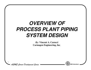
25Figure 9 NOTES:1. This drawing is meant to demonstrate system piping concept only. Installer is responsible for all equipment and detailing required by local codes.2. Boiler circulator(s) must be rated for open loop applications. Do not use cast-iron circulators.3. Boiler circulator(s) operate continuously.4. The minimum pipe size for connecting to a water storage tank is 1 ½”.5. The minimum pipe size for connecting the boiler is 1 ½” for the Mod Con 300 VWH and 2” for the 500 and 850 models.6. All pumps are shown with isolation flanges or full port ball valves for isolation. The alternative is standard flanges with full port ball valves and aseparate flow check valve.7. Install a minimum of 12 diameters of straight pipe upstream of all circulators and check valves.8. Install a vacuum relief valve in accordance with local code requirements.9. Multiple boilers and storage tanks shall be installed with reverse return piping (as shown).10. Mixing valves are recommended on all tanks if hot water temperature is above 119oF.11. Expansion tank must be rated for use with potable water.12. Use either indirect/tank sensor or system/pipe sensor mounted on common return to the boiler.13. Wire the tank or system/pipe sensor connected to the DHW sensor terminals on the follower boiler addressed as #1.14. The system/pipe sensor must be placed on common piping to the tank, as close to the tank as possible.15. The system/pipe sensor is wired to the system sensor terminals on the master boiler.LP- 276 REV. 3.28.14
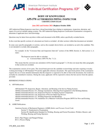
26Figure 10 NOTES:1. This drawing is meant to demonstrate system piping concept only. Installer is responsible for all equipment and detailing required by local codes.2. Boiler circulator(s) must be rated for open loop applications. Do not use cast-iron circulators.3. Boiler circulator(s) operate continuously.4. The minimum pipe size for connecting to a water storage tank is 1 ½”.5. The minimum pipe size for connecting the boiler is 1 ½” for the Mod Con 300 VWH and 2” for the 500 and 850 models.6. All pumps are shown with isolation flanges or full port ball valves for isolation. The alternative is standard flanges with full port ball valves and aseparate flow check valve.7. Install a minimum of 12 diameters of straight pipe upstream of all circulators and check valves.8. Install a vacuum relief valve in accordance with local code requirements.9. Multiple boilers and storage tanks shall be installed with reverse return piping (as shown).10. Mixing valves are recommended on all tanks if hot water temperature is above 119oF.11. Expansion tank must be rated for use with potable water.12. Use either indirect/tank sensor or system/pipe sensor mounted on common return to the boiler.13. Wire the tank or system/pipe sensor connected to the DHW sensor terminals on the follower boiler addressed as #1.14. The system/pipe sensor must be placed on common piping to the tank, as close to the tank as possible.15. The system/pipe sensor is wired to the system sensor terminals on the master boiler.LP- 276 REV. 3.28.14
27Figure 11NOTES:1. This drawing is meant to demonstrate system piping concept only. Installer is responsible for all equipment and detailing required by local codes.2. Boiler circulator(s) must be rated for open loop applications. Do not use cast-iron circulators.3. Boiler circulator(s) operate continuously.4. The minimum pipe size for connecting to a water storage tank is 1 ½”.5. The minimum pipe size for connecting the boiler is 1 ½” for the Mod Con 300 VWH and 2” for the 500 and 850 models.6. All pumps are shown with isolation flanges or full port ball valves for isolation. The alternative is standard flanges with full port ball valves and aseparate flow check valve.7. Install a minimum of 12 diameters of straight pipe upstream of all circulators and check valves.8. Install a vacuum relief valve in accordance with local code requirements.9. Multiple boilers and storage tanks shall be installed with reverse return piping (as shown).10. Mixing valves are recommended on all tanks if hot water temperature is above 119oF.11. Expansion tank must be rated for use with potable water.12. Use either indirect/tank sensor or system/pipe sensor mounted on common return to the boiler.13. Wire the tank or system/pipe sensor connected to the DHW sensor terminals on the follower boiler addressed as #1.14. The system/pipe sensor must be placed on common piping to the tank, as close to the tank as possible.15. The system/pipe sensor is wired to the system sensor terminals on the master boiler.LP- 276 REV. 3.28.14
28Figure 12NOTES:1. This drawing is meant to demonstrate system piping concept only. Installer is responsible for all equipment and detailing required by local codes.2. Boiler circulator(s) must be rated for open loop applications. Do not use cast-iron circulators.3. Boiler circulator(s) operate continuously.4. The minimum pipe size for connecting to a water storage tank is 1 ½”.5. The minimum pipe size for connecting the boiler is 1 ½” for the Mod Con 300 VWH and 2” for the 500 and 850 models.6. All pumps are shown with isolation flanges or full port ball valves for isolation. The alternative is standard flanges with full port ball valves and aseparate flow check valve.7. Install a minimum of 12 diameters of straight pipe upstream of all circulators and check valves.8. Install a vacuum relief valve in accordance with local code requirements.9. Multiple boilers and storage tanks shall be installed with reverse return piping (as shown).10. Mixing valves are recommended on all tanks if hot water temperature is above 119oF.11. Expansion tank must be rated for use with potable water.12. Use either indirect/tank sensor or system/pipe sensor mounted on common return to the boiler.13. Wire the tank or system/pipe sensor connected to the DHW sensor terminals on the follower boiler addressed as #1.14. The system/pipe sensor must be placed on common piping to the tank, as close to the tank as possible.15. The system/pipe sensor is wired to the system sensor terminals on the master boiler.PART 5 – VENTING, COMBUSTION AIR AND CONDENSATE REMOVALThe boiler must be vented as detailed in this Venting Section. Ensure exhaust and intake piping complies with these instructionsregarding vent system. Inspect finished combustion air intake and exhaust piping thoroughly to ensure all joints are well secured,airtight, and comply with all applicable code requirements, as well as with the instructions provided in this manual. Failure to properlyinstall the vent system will result in property damage, severe personal injury, or death.A. GENERALThis boiler is certified as a “Category IV” appliance, and requires a special venting system. The vent system will operate with a positivepressure in the pipe. Exhaust gases must be piped directly outdoors using the vent materials and rules outlined in these instructions.Do not connect vent connectors serving appliances vented by natural draft into any portion of mechanical draft systems operating underpositive pressure. Follow the venting instructions below carefully. Failure to do so will result in substantial property damage, severepersonal injury, or death.LP- 276 REV. 3.28.14
This drawing is meant to demonstrate system piping concept only. Installer is responsible for all equipment and detailing required by local codes. 2. Boiler circulator(s) must be rated for open loop applications. Do not use cast-iron circulators. 3. Boiler circulator(s) operate continuousl