Transcription
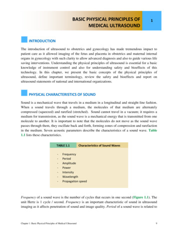
BASIC PHYSICAL PRINCIPLES OFMEDICAL ULTRASOUND1INTRODUCTIONThe introduction of ultrasound to obstetrics and gynecology has made tremendous impact topatient care as it allowed imaging of the fetus and placenta in obstetrics and maternal internalorgans in gynecology with such clarity to allow advanced diagnosis and also to guide various lifesaving interventions. Understanding the physical principles of ultrasound is essential for a basicknowledge of instrument control and also for understanding safety and bioeffects of thistechnology. In this chapter, we present the basic concepts of the physical principles ofultrasound, define important terminology, review the safety and bioeffects and report onultrasound statements of national and international organizations.PHYSICAL CHARACTERISTICS OF SOUNDSound is a mechanical wave that travels in a medium in a longitudinal and straight-line fashion.When a sound travels through a medium, the molecules of that medium are alternatelycompressed (squeezed) and rarefied (stretched). Sound cannot travel in a vacuum; it requires amedium for transmission, as the sound wave is a mechanical energy that is transmitted from onemolecule to another. It is important to note that the molecules do not move as the sound wavepasses through them, they oscillate back and forth, forming zones of compression and rarefactionin the medium. Seven acoustic parameters describe the characteristics of a sound wave. Table1.1 lists these characteristics.TABLE 1.1-Characteristics of Sound gthPropagation speedFrequency of a sound wave is the number of cycles that occurs in one second (Figure 1.1). Theunit Hertz is 1 cycle / second. Frequency is an important characteristic of sound in ultrasoundimaging as it affects penetration of sound and image quality. Period of a sound wave is related toChapter 1: Basic Physical Principles of Medical Ultrasound9
the time that a wave takes to vibrate up and down and thus is reciprocally related to frequency.For instance, a sound wave with a frequency of 10 Hertz will have a period of 1/10 second.Amplitude, power and intensity are three wave characteristics that relate to the strength of asound wave. Amplitude is defined by the difference between the peak (maximum) or trough(minimum) of the wave and the average value (Figure 1.2). The peak or crest, represents thezone of compression and the trough represents the zone of rarefaction (Figure 1.2). Units ofamplitudes are expressed in pressure parameters (Pascals) and in clinical imaging in millionPascals (MPa). The amplitude of a sound wave diminishes as sound propagates through thebody. Power is the rate of energy transferred through the sound wave and is expressed in Watts.Power is proportional to the amplitude squared of a sound wave. Power can be altered up ordown by a control on the ultrasound machine. Intensity is the concentration of energy in a soundwave and thus is dependent on the power and the cross sectional area of the sound beam. Theintensity of a sound beam is thus calculated by dividing the power of a sound beam (Watts) by itscross sectional area (cm2), expressed in units of W/cm2. The wavelength of a sound wave is thelength of a wave and is defined as the distance of a complete cycle. It is designated by thesymbol lambda (λ), is expressed in mm in clinical settings (Figure 1.3), and can be calculated bydividing the velocity of the wave by the frequency of the wave (λ v/f). The propagation speedis the distance that a sound wave travels through a specified medium in 1 second.Figure 1.1: Frequency of sound is the number of cycles persecond (s) and is expressed in Hertz (1 cycle / sec). In WaveA, the frequency is 2 cycles per sec or 2 Hertz and in wave Bthe frequency is 3 cycles per sec or 3 Hertz. The doublearrows denote sound wavelengths, described in figure 1.3.Chapter 1: Basic Physical Principles of Medical Ultrasound10
Figure 1.2: Amplitude (A) is defined by the difference betweenthe peak (maximum) or trough (minimum) of the wave and theaverage value. Units of amplitude are expressed in millionPascals (MPa).Figure 1.3: The wavelength of a sound wave is the length of a wave and is defined asthe distance of a complete cycle. It is designated by the symbol lambda (λ), and isexpressed in mm. In this schematic, 3 sound waveforms are shown with respectivelyshorter wavelengths from A to C.Chapter 1: Basic Physical Principles of Medical Ultrasound11
TABLE 1.2Speed of Sound in Various MediaMedium TypeSpeed (m/s)AirFatWaterSoft Tissue3301,4501,4501,540BoneMetals3,500up to 7,000The sound source, which is the ultrasound machine and/or the transducer, determines thefrequency, period, amplitude, power and intensity of the sound. Wavelength is determined byboth the sound source and the medium and the propagation speed is a function of the mediumonly. The propagation speed of sound in soft tissue is constant at 1,540 m/s. Table 1.2 shows thepropagation of sound in other biologic media and materials.WHAT IS ULTRASOUND?Sound is classified based upon the ability of the human ear to hear it. Sounds sensed by younghealthy adult human ears are in the range of 20 cycles per second or Hertz, abbreviated as Hz, to20,000 Hz, or 20 KHz (Kilo Hertz) termed audible sound (Range of 20 – 20,000 Hz). If thefrequency of a sound is less than 20 Hz, it cannot be heard by humans and is defined asinfrasonic or infrasound. If the frequency of sound is higher than 20 KHz, it cannot be heard byhumans and is called ultrasonic or ultrasound, Table 1.3. Typical frequencies used in medicalultrasound are 2-10 MHz (mega, (million), Hertz). Ultrasound frequencies that are commonlyused in obstetrics and gynecology are between 3 and 10 MHz.TABLE 1.3Frequency Spectrum of SoundSound WaveFrequencyUltrasoundGreater than 20 KHzAudible Sound20 Hz to 20 KHzInfrasoundLess than 20 HzChapter 1: Basic Physical Principles of Medical Ultrasound12
HOW IS ULTRASOUND GENERATED?Ultrasound waves are generated from tiny piezoelectric crystals packed within the ultrasoundtransducers (Figure 1.4). When an alternate current is applied to these crystals, they contract andexpand at the same frequency at which the current changes polarity and generate an ultrasoundbeam. The ultrasound beam traverses into the body at the same frequency generated. Conversely,when the ultrasound beam returns to the transducer, these crystals change in shape and this minorchange in shape generate a tiny electric current that is amplified by the ultrasound machine togenerate an ultrasound image on the monitor. The piezoelectric crystals within the transducertherefore transform electric energy into mechanical energy (ultrasound) and vice-versa. Onecrystal is not sufficient to produce an ultrasound beam for clinical imaging and moderntransducers have large number of crystals arranged into parallel rows (Figure 1.4). Each crystalcan nevertheless be stimulated individually. The crystals are protected by a rubber covering thathelps decrease the resistance to sound transmission (impedance) from the crystals to the body.The high frequency sound generated by a transducer do not travel well through air, so in order tofacilitate their transfer from the transducer to the skin of the patient, a watery gel is applied thatcouples the transducer to the skin and permits the sound to go back and forth. Ultrasound istherefore generated inside transducers by tiny crystals that convert electric current to ultrasoundand convert returning ultrasound beams from the body into electric currents. Modern transducershave crystals made of synthetic plumbium zirconium titanate (PZT).Figure 1.4: Piezoelectric crystals shown within a transducer. Note the symmetrical arrangement of thecrystals. This figure is a diagrammatic representation, as the crystals are typically much smaller thanshown. Figure 1.4 is modified with permission from the Society of Ultrasound in Medical Education(SUSME.org).Chapter 1: Basic Physical Principles of Medical Ultrasound13
HOW IS AN ULTRASOUND IMAGE FORMED?Modern ultrasound equipment create an ultrasound image by sending multiple sound pulses fromthe transducer at slightly different directions and analyzing returning echoes received by thecrystals. Details of this process is beyond the scope of this book, but it is important to note thattissues that are strong reflectors of the ultrasound beam, such as bone or air will result in a strongelectric current generated by the piezoelectric crystals which will appear as a hyperechoic imageon the monitor (Figure 1.5). On the other hand, weak reflectors of ultrasound beam, such as fluidor soft tissue, will result in a weak current, which will appear as a hypoechoic or anechoic imageon the monitor (Figure 1.5). The ultrasound image is thus created from a sophisticated analysisof returning echoes in a grey scale format. Given that the ultrasound beam travels in alongitudinal format, in order to get the best possible image, keep the angle of incidence of theultrasound beam perpendicular to the object of interest, as the angle of incidence is equal to theangle of reflection (Figure 1.6).Figure 1.5: Ultrasound image of fetal extremities in the second trimester. Note thehyperechoic femur, the hypoechoic soft tissue in the thigh and anechoic amnioticfluid. Calipers measure the maximal vertical pocket of amniotic fluid (chapter 9).Chapter 1: Basic Physical Principles of Medical Ultrasound14
Figure 1.6: Ultrasound image of fetal lower extremity in the second trimesterdemonstrating the effect of the angle of insonation. Note how clearly the tibia is seen,as the angle of insonation is almost 90 degrees to it. The femur is barely seen, as theangle of insonation is almost parallel to it.WHAT ARE DIFFERENT TYPES OF ULTRASOUND MODES?A-mode, which stands for “Amplitude mode”, is no longer used in clinical obstetric andgynecologic ultrasound imaging but was the basis of modern ultrasound imaging. In A-modedisplay, a graph shows returning ultrasound echoes with the x-axis representing depth in tissuesand the y-axis representing amplitude of the returning beam. Historically, A-mode ultrasoundwas used in obstetrics in measuring biparietal diameters (Figure 1.7). B-mode display, whichstands for “Brightness mode”, known also as two-dimensional imaging, is commonly used todescribe any form of grey scale display of an ultrasound image. The image is created based uponthe intensity of the returning ultrasound beam, which is reflected in a variation of shades of greythat form the ultrasound image (Figure 1.8). It is important to note that B-mode is obtained inreal-time, an important and fundamental characteristic of ultrasound imaging. Table 1.4 showsvarious echogenicity of normal fetal tissue.Chapter 1: Basic Physical Principles of Medical Ultrasound15
Figure 1.7: A-Mode ultrasound of fetal head. The first spike corresponds to theanterior cranium and the second spike corresponds to the posterior cranium.The biparietal diameter is the distance between these 2 spikes.Figure 1.8: Variations in grey scale in a 2D ultrasound image of afetal abdomen in the second trimester. Note the hyperechoic ribsand lung tissue, hypoechoic liver and anechoic umbilical vein. Theintensity of the returning beam determines echogenicity.Chapter 1: Basic Physical Principles of Medical Ultrasound16
TABLE 1.4Various Ultrasound Echogenicity of Fetal TissueOrgan ladderPlacentaAmniotic FluidAnechoicSlightly EchoicMore EchoicEchogenic M-mode display, which stands for “Motion mode” is a display that is infrequently used in currentultrasound imaging but is specifically used to assess the motion of the fetal cardiac chambers andvalves in documentation of fetal viability and to assess certain fetal cardiac conditions such asarrhythmias and congenital heart disease. The M-mode originates from a single beam penetratingthe body with a high pulse repetition frequency. The display on the monitor shows the time ofthe M-mode display on the x-axis and the depth on the y axis (Figure 1.9).Figure 1.9: M-mode ultrasound of the fetal heart in the second trimester. The Mmode display (in sepia color) corresponds to the single ultrasound beam (dashedyellow line) with the X-axis displaying time and Y-axis displaying depth. Note thedisplay of the heart on B-mode and corresponding M-mode shown by the doubleheaded arrows.Chapter 1: Basic Physical Principles of Medical Ultrasound17
Color and spectral (pulsed) Doppler modes are dependent on the Doppler principle (effect). TheDoppler principle describes the apparent variation in frequency of a light or a sound wave as thesource of the wave approaches or moves away, relative to an observer. The traditional examplethat is given to describe this physical phenomenon is the apparent change in sound level of atrain as the train approaches and then departs a station. The sound seems higher in pitch as thetrain approaches the station and seems lower in pitch as the train departs the station. Thisapparent change in sound pitch, or what is termed the frequency shift, is proportional to thespeed of movement of the sound-emitting source, the train in this example. It is important to notethat the actual sound of the train is not changing; it is the perception of change in sound to astationary observer that determines the “Doppler effect”. In clinical applications, whenultrasound with a certain frequency (fo) is used to insonate a certain blood vessel, the reflectedfrequency (fd) or frequency shift is directly proportional to the speed with which the red bloodcells are moving (blood flow velocity) within that particular vessel. This frequency shift of thereturning signal is displayed in a graphic form as a time-dependent plot. In this display, thevertical axis represents the frequency shift and the horizontal axis represents the temporal changeof this frequency shift as it relays to the events of the cardiac cycle (Figure 1.10). This frequencyshift is highest during systole, when the blood flow is fastest and lowest during end diastole,when the blood flow is slowest in the peripheral circulation (Figure 1.10). Given that thevelocity of flow in a particular vascular bed is inversely proportional to the downstreamimpedance to flow, the frequency shift therefore derives information on the downstreamimpedance to flow of the vascular bed under study. The frequency shift is also dependent on thecosine of the angle that the ultrasound beam makes with the targeted blood vessel (see formula inFigure 1.10). Given that the insonating angle (angle of incidence) is difficult to measure inclinical practice, indices that rely on ratios of frequency shifts were developed to quantitateDoppler waveforms. By relying on ratios of frequency shifts, these Doppler indices are thusindependent of the effects of the insonating angle of the ultrasound beam. Doppler indices thatare commonly used in obstetric and gynecologic practice are shown in (Figure 1.11).Chapter 1: Basic Physical Principles of Medical Ultrasound18
Figure 1.10: Doppler velocimetry of the umbilical artery at the abdominal cord insertion. “S”corresponds to the frequency shift during peak systole and “D” corresponds to the frequencyshift during end diastole. The Doppler effect formula is also shown in white background.(Schematic of Doppler formula modified with permission from A Practical Guide to FetalEchocardiography Normal and Abnormal Hearts – Abuhamad, Chaoui, second edition –Wolters Kluwer.Figure 1.11: Doppler waveforms formulas that are commonly used in obstetrics andgynecology. PI pulsatility index, RI resistive index, S peak systolic frequencyshift, D end diastolic frequency shift and M mean frequency shift. Reproducedwith permission from A Practical Guide to Fetal Echocardiography: Normal andAbnormal Hearts – Abuhamad, Chaoui, second edition – Wolters Kluwer.Chapter 1: Basic Physical Principles of Medical Ultrasound19
Figure 1.12: Color Doppler mode of the cord insertion into a posteriorplacenta. Blood in the umbilical vein is colored red (towards the transducer)and blood in the umbilical arteries is colored blue (away from thetransducer).Color Doppler mode or Color flow mode is a mode that is superimposed on the real-time Bmode image. This mode is used to detect the presence of vascular flow within the tissue beinginsonated (Figure 1.12). By convention, if the flow is towards the transducer it is colored redand if the flow is away from the transducer it is colored blue. The operator controls variousparameters of color Doppler such as the velocity scale or pulse repetition frequency (PRF), wallfilter, size of the area within the field of B-mode and the angle of incidence that the ultrasoundbeam makes with the direction of blood flow. Low velocity scales and filters are reserved for lowimpedance vascular beds such as ovarian flow in gynecology (Figure 1.13) and high velocityscales and filters are reserved for high impedance circulation such as cardiac outflow tracts(Figure 1.14). In order to optimize the display of color Doppler, the angle of insonation shouldbe as parallel to the direction of blood flow as possible. If the angle of insonation approachesninety degrees, no color flow will be displayed given that the “Doppler effect” is dependent onthe cosine of the angle of insonation, and cosine of 90 degrees is equal to zero (Figure 1.15).Chapter 1: Basic Physical Principles of Medical Ultrasound20
Figure 1.13: Color Doppler mode of blood flow within theovary (labeled). Typically ovarian flow is low impedance anddetected on low velocity scale with low filter setting.Figure 1.14: Color Doppler mode of left ventricular outflow inthe fetal heart. Blood flow in the fetal heart has high velocityand thus is detected on high velocity scale. LV left ventricle,RV right ventricle, Ao aorta.Chapter 1: Basic Physical Principles of Medical Ultrasound21
Figure 1.15: Blood flow in an umbilical cord showing theDoppler Effect. White arrows show the direction of bloodflow. Note the absence of blood flow on color Doppler(asterisk) where the ultrasound beam (grey arrow) images thecord with an angle of insonation equal to 90 degrees. Theblack arrows represent blood flow with an angle of insonationalmost parallel to the ultrasound beam and thus display thebrightest color corresponding to the highest velocities.In the spectral Doppler mode, or pulsed Doppler mode, quantitative assessment of vascular flowcan be obtained at any point within a blood vessel by placing a sample volume or the gate withinthe vessel (Figure 1.16). Similar to color Doppler, the operator controls the velocity scale, wallfilter and the angle of incidence. Flow towards the transducer is displayed above the baseline andflow away from the transducer is displayed below the baseline. In spectral Doppler mode, onlyone crystal is typically necessary and it alternates between sending and receiving ultrasoundpulses.Chapter 1: Basic Physical Principles of Medical Ultrasound22
Figure 1.16: Pulsed Doppler mode of the umbilical artery. Scorresponds to the frequency shift during peak systole and Dcorresponds to the frequency shift at end diastole.Doppler mode, or Energy mode, or High Definition Doppler mode is a sensitive mode ofDoppler that is available on some high-end ultrasound equipment and is helpful in the detectionof low velocity flow (Figure 1.17). The strength (amplitude) of the reflected signal is primarilyprocessed. Power Doppler mode is less affected by the angle of insonation than the traditionalcolor or spectral Doppler.Figure 1.17: Power Doppler mode showing vascularity withina borderline ovarian tumor. Power Doppler mode is helpfulin the detection of low velocity flow.Chapter 1: Basic Physical Principles of Medical Ultrasound23
WHAT ARE THE BIOEFFECTS OF ULTRASOUND?Ultrasound is a form of mechanical energy and its output varies based upon the mode applied. Ingeneral B-mode has the lowest energy and pulsed Doppler has the highest energy. Given thepresence of a theoretical and potential harm of ultrasound, the benefit to the patient must alwaysoutweigh the risk. In general, ultrasound is considered to be a safe imaging modality ascompared to other imaging modalities that have ionizing radiation like X-ray and ComputedTomography (CT). There are 2 important indices for measurement of bioeffects of ultrasound;the Thermal Index (TI) and the Mechanical Index (MI). The Thermal Index is a predictor ofmaximum temperature increase under clinically relevant conditions and is defined as the ratio ofthe power used over the power required to produce a temperature rise of 1 C. The TI is reportedin three forms; TIS or Thermal index Soft tissue, assumes that sound is traveling in soft tissue,TIB or Thermal index Bone, assumes that sound is at or near bone, TIC, or Thermal indexCranial assumes that the cranial bone is in the sound beam’s near field. The Mechanical index(MI) gives an estimation of the cavitation effect of ultrasound, which results from the interactionof sound waves with microscopic, stabilized gas bubbles in the tissues. Other effects included inthis category are physical (shock wave) and chemical (release of free radicals) effects ofultrasound on tissue.In 1992, the Output Display Standard (ODS) was mandated for all diagnostic ultrasound devices.In this ODS, the manufacturers are required to display in real time, the TI and the MI on theultrasound screen with the intent of making the user aware of bioeffects of the ultrasoundexamination (Figure 1.18). The user has to be aware of the power output and make sure thatreasonable levels are maintained. Despite the lack of scientific reports of confirmed harmfulbioeffect from exposure to diagnostic ultrasound, the potential benefit and risk of the ultrasoundexamination should be assessed and the principle of ALARA should be always followed. TheALARA principle stands for As Low As Reasonably Achievable when adjusting controls of theultrasound equipment in order to minimize the risk. Always keep track of the TI and MI valueson the ultrasound screen, and keep the TI below 1 and MI below 1 for obstetrical ultrasoundimaging.Chapter 1: Basic Physical Principles of Medical Ultrasound24
Figure 1.18: An ultrasound examination of the fetal abdomen in thethird trimester of pregnancy. Note the display of MI and TIb in whiterectangle. MI Mechanical Index and TIb Thermal Index bone.WHAT ARE SOME RELEVANT OFFICIAL STATEMENTS FROM ULTRASOUNDSOCIETIES?Several national and international societies have official statements that relates to the use ofmedical ultrasound in obstetrics and gynecology. We have assembled in this chapter some of therelevant official statements along with the Internet link to their source. It is important to note thatofficial societal statements tend to be updated from time to time and the reader should consultwith the society’s website for the most recent version.International Society of Ultrasound in Obstetrics and Gynecology (ISUOG)(www.ISUOG.org)ISUOG- Statement on the safe use of Doppler in the 11 to 13 6-week fetal ultrasoundexamination (1):1) Pulsed Doppler (spectral, power and color flow imaging) ultrasound should not be usedroutinely.2) Pulsed Doppler ultrasound may be used for clinical indications such as to refine risks fortrisomies.Chapter 1: Basic Physical Principles of Medical Ultrasound25
3) When performing Doppler ultrasound, the displayed thermal index (TI) should be 1.0and exposure time should be kept as short as possible (usually no longer than 5–10 min)and should not exceed 60 min.4) When using Doppler ultrasound for research, teaching and training purposes, thedisplayed TI should be 1.0 and exposure time should be kept as short as possible(usually no longer than 5–10 min) and should not exceed 60 min. Informed consentshould be obtained.5) In educational settings, discussion of first-trimester pulsed or color Doppler should beaccompanied by information on safety and bioeffects (e.g. TI, exposure times and how toreduce output power)6) When scanning maternal uterine arteries in the first trimester, there are unlikely to be anyfetal safety implications as long as the embryo/fetus lies outside the Doppler ultrasoundbeam.ISUOG- Safety Statement, 2000 (reconfirmed 2003) (2):The thermal index (TI) and the mechanical index (MI) are not perfect indicators of the risks ofthermal and nonthermal bioeffects, but currently they should be accepted as the most practicaland understandable methods of estimating the potential for such risks.B-mode and M-modeAcoustic outputs are generally not high enough to produce deleterious effects. Their usetherefore appears to be safe, for all stages of pregnancy.Doppler UltrasoundSignificant temperature increase may be generated by spectral Doppler mode, particularly in thevicinity of bone. This should not prevent use of this mode when clinically indicated, provided theuser has adequate knowledge of the instrument’s acoustic output, or has access to the relevant TI.Caution is recommended when using color Doppler mode with a very small region of interest,since this mode produces the highest potential for bioeffects. When ultrasound examination isclinically indicated, there is no reason to withhold the use of scanners that have received currentFood and Drug Administration clearance in tissues, which have no identifiable gas bodies. Sinceultrasound contrast agents are mostly gas-carriers, the risk of induction and sustenance of inertialcavitation is higher in circumstances when these agents are employed.PregnancyBased on evidence currently available, routine clinical scanning of every woman duringpregnancy using realtime B-mode imaging is not contraindicated. The risk of damage to the fetusby teratogenic agents is particularly great in the first trimester. One has to remember that heat isgenerated at the transducer surface when using the transvaginal approach. Spectral and colorDoppler may produce high intensities and routine examination by this modality during theembryonic period is rarely indicated. In addition, because of high acoustic absorption by bone,the potential for heating adjacent tissues must also be kept in mind. Exposure time and acousticoutput should be kept to the lowest levels consistent with obtaining diagnostic information andlimited to medically indicated procedures, rather than for purely entertainment purposes.Chapter 1: Basic Physical Principles of Medical Ultrasound26
EducationEducation of ultrasound operators is of the utmost importance since the responsibility for the safeuse of ultrasound devices is now shared between the users and the manufacturers, who shouldensure the accuracy of the output display.ISUOG-Statement on the non-medical use of ultrasound (2009) (3):The International Society of Ultrasound in Obstetrics and Gynecology (ISUOG) and WorldFederation of Ultrasound in Medicine and Biology (WFUMB) disapprove of the use ofultrasound for the sole purpose of providing souvenir images of the fetus. There have been noreported incidents of human fetal harm in over 40 years of extensive use of medically indicatedand supervised diagnostic ultrasound. Nevertheless, ultrasound involves exposure to a form ofenergy, so there is the potential to initiate biological effects. Some of these effects might, undercertain circumstances, be detrimental to the developing fetus. Therefore, the uncontrolled use ofultrasound without medical benefit should be avoided. Furthermore, ultrasound should beemployed only by health professionals who are trained and updated in the clinical usage andbioeffects of ultrasound.American Institute of Ultrasound in Medicine (AIUM) (www.AIUM.org)AIUM-As Low As Reasonably Achievable (ALARA) Principle (2008) (4):The potential benefits and risks of each examination should be considered. The ALARA (AsLow As Reasonably Achievable) Principle should be observed when adjusting controls thataffect the acoustical output and by considering transducer dwell times. Further details onALARA may be found in the AIUM publication "Medical Ultrasound Safety.AIUM-Conclusions Regarding Epidemiology for Obstetric Ultrasound (2010) (5):Based on the epidemiologic data available and on current knowledge of interactive mechanisms,there is insufficient justification to warrant conclusion of a causal relationship betweendiagnostic ultrasound and recognized adverse effects in humans. Some studies have reportedeffects of exposure to diagnostic ultrasound during pregnancy, such as low birth weight, delayedspeech, dyslexia and non-right-handedness. Other studies have not demonstrated such effects.The epidemiologic evidence is based primarily on exposure conditions prior to 1992, the year inwhich acoustic limits of ultrasound machines were substantially increased for fetal/obstetricapplicationsAIUM-Prudent Use and Clinical Safety (2012) (6):Diagnostic ultrasound has been in use since the late 1950s. Given its known benefits andrecognized efficacy for medical diagnosis, including use during human pregnancy, the AmericanInstitute of Ultrasound in Medicine herein addresses the clinical safety of such use:Chapter 1: Basic Physical Principles of Medical Ultrasound27
No independently confirmed adverse effects caused by exposure from present diagnosticultrasound instruments have been reported in human patients in the absence of contrast agents.Biological effects (such as localized pulmonary bleeding) have been reported in mammaliansystems at diagnostically relevant exposures but the clinical significance of such effects is not yetknown. Ultrasound should be used by qualified health professionals to provide medical benefit tothe patient. Ultrasound exposures during examinations should be as low as reasonably achievable(ALARA).AIUM-Prudent Use in Pregnancy (2012) (7):The AIUM advocates the responsible use of diagnost
Chapter 1: Basic Physical Principles of Medical Ultrasound 11 Figure 1.2: Amplitude (A) is defined by the diffe