Transcription
Custom Connections
Autodesk Advance Steel Custom ConnectionsTable of ContentsAUTODESK ADVANCE STEEL CUSTOM CONNECTIONS .5INTRODUCTION . 6STANDARD ELEMENTS AS CUSTOM CONNECTIONS . 7AUTOMATIC JOINTS AS CUSTOM CONNECTIONS . 13AUTOMATIC JOINTS AND THEIR USE . 13AUTOMATIC JOINTS AS CUSTOM CONNECTIONS . 15INTELLIGENT BRICKS AS CUSTOM CONNECTIONS . 20INTELLIGENT BRICKS AND THEIR USE . 20Plate along beam flange . 21Plate on beam flange . 24Plate parallel beam flange . 26Plate along beam web . 28Plate on beam web . 30Plate parallel beam web. 32Bolts on beam . 34Bolts on gauge line . 37Studs on beam.39Bolts/Anchors/Holes on plate. 41Studs on plate . 43Galvanizing holes. 45Plate on plate . 47Plate perpendicular to plate . 49Plate at plate edge . 51Spacer plates . 53Shim plates at bolts. 56Outside stiffener. 58Beam on object reference to object . 60Plate on object reference to object . 63Hole in beam reference to beam . 65INTELLIGENT BRICKS AS CUSTOM CONNECTIONS . 673
AUTODESK ADVANCE STEEL CUSTOMCONNECTIONS
Autodesk Advance Steel Custom ConnectionsIntroductionStarting with version 2013 of Autodesk Advance Steel, you have the possibility to define, save and reuse CustomConnections. You can find all required functions in the tool palette, "Custom Connections" category.Custom Connections can be defined as follows: From all standard elements like beams, plates, special parts, folded plates, bolts, welds, features, weldpreparations, etc. From automatic joints From intelligent bricksYou can also combine parts from all the groups mentioned above.The purpose of this tutorial is to show you the different possibilities of defining and reusing Custom Connections.6
Autodesk Advance Steel Custom ConnectionsStandard Elements as Custom ConnectionsStarting with version 2013 of Autodesk Advance Steel, you have the possibility to convert standard element likebeams, plates, special parts, folded plates, bolts, welds, features, weld preparations, etc. to intelligent CustomConnections, to save them and to reuse them in other projects. Therefore, one requirement is to save the DWG-file nnectionTemplates, so that the drawing can beaccessed later by Advance Steel, when you want to reuse the Custom Connection.One of these drawings can contain several Custom Connections and the path mentioned above can contain severaldrawings.If you create Custom Connections directly in your model, these Custom Connections can be reused only in thisproject. This can be useful for special situations, too.Now, open a new drawing first by using the template ASTemplate.dwt.Note:You can also create all elements for the Custom Connection in your current model and then insert all theparts needed for the Custom Connection into a separate DWG-file by using the command "block". Youmust save the new file at the path mentioned above.Create all parts which are important for the Custom Connection, including the components which will be connected bythe joint, in the new drawing.For this tutorial, we want to create the following connection:Make sure that all standard elements which are important for the Custom Connection are visible and can be selected,including all the green frames for features, and all the welds.Save the DWG-file atC:\ProgramData\Autodesk\Advance ion.dwg.7
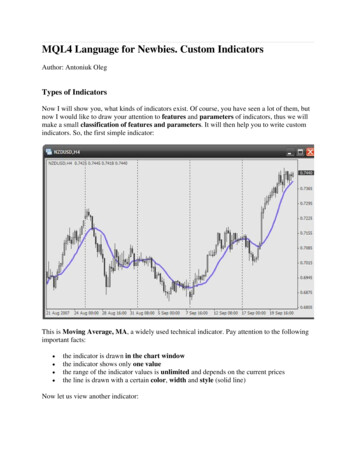
Autodesk Advance Steel Custom ConnectionsNow, create the Custom Connection by using the command "Create connection template" from the tool palette,"Custom Connection" category.The window "Choose the definition method" appears.In our example, we want to insert the new Custom Connection depending on a main and a second beam, so wechoose "2 beams" from the menu.The following prompt appears:Select input beam:Select the main beam first and confirm your selection by right click; select the second beam and confirm your selectionby right click. Now both beams are defined.The window "User template" appears.8
Autodesk Advance Steel Custom ConnectionsEnter the name of the Custom Connection in the "Name" field, e.g. "Angle Connection".button behind "Reselect driven/output objects". Press theYou can select the parts of the joint by pressing thebutton and select all parts e.g. by window, make sure that all features and connecting elements (bolts, welds, etc.) areselected too.In the fields of the "Drivers selection prompts:" table you can enter the terms which will appear in command linewhen you reuse the Custom Connection to select the members of the joint. If you click in one of the lines of the table,the corresponding element in the model will be marked red and you can modify the text in this line.After you have done all required settings in this window, close it by pressing X in the upper right corner. The CustomConnection was created successfully. In the model you can see this on the blue box, which includes all elements,which belong to the Custom Connection.Go back to your model to reuse the new Custom Connection named "Angle Connection" there.Initial situation:9
Autodesk Advance Steel Custom ConnectionsClick "Insert connection template" from the tool palette, "Custom Connection" category.The "Connection template explorer" appears. Here you can see on the left side the "Angle.dwg" category (name ofthe drawing containing the Custom Connection) and the Custom Connection itself. At the right side you can see apreview of the Custom Connection. Above the preview you can find all commands for zoom, pan and orbit.Select the Custom Connection and press "OK".In the command line, the terms which you have specified during the definition of the Custom Connection appear.Select the corresponding elements in the model.The Custom Connection is inserted. This connection can be identified by a blue box in the model as CustomConnection.10
Autodesk Advance Steel Custom ConnectionsThe "User template" window with the properties of the Custom Connection appears.All settings are greyed out here, because the Custom Connection is exactly the same as the template connection youhave defined. The settings within the properties dialog boxes of the connection members are greyed out, too. Thissituation we know from the automatic joints.11
Autodesk Advance Steel Custom ConnectionsIf you have to modify properties of the Custom Connection later, you can do this without deleting the blue box anddestroying the intelligence of the Custom Connection by selecting the blue box, making a right click and choosing"Custom Connection Properties" from the context menu.The window "User template" appears again and you can activate the option "Allow object modification". Now youcan modify the properties of all elements of the Custom Connection without losing the connections intelligence.Now all "Advance Properties" e.g. of the bolts can be modified:12
Autodesk Advance Steel Custom ConnectionsAutomatic Joints as Custom ConnectionsAutomatic Joints and their useAutomatic Joints are intelligent connections, which you can insert in your model by using Connection vault ofAdvance Steel. You can find the Connection vault in the ribbon"Extended Modeling", category "Joints":You can use all joints from the Connection vault at any time in your Autodesk Advance Steel model, at any situation,which fits to the properties of the joint and how often you need them.Depending on the joint, the properties dialog box contains many settings to adapt the connection to the situation in themodel.13
Autodesk Advance Steel Custom ConnectionsIf you need the same joint may times within one model with the same properties, you can use the command "Createby template", which you can find in ribbon "Extended Modeling", category "Joint Utilities" to do this.If you need some automatic joints with special settings in different models, then you can insert this joint in a model andmake all settings you need. After that you can go the tab "Library" in the properties dialog box of the joint and savethe settings by pressing the button "Import values". After that you can modify the values by pressing the button "Edit"if needed.If you reuse this joint later in another model for the same beams, then Autodesk Advance Steel recognizes that youhave saved values for this joint and this combination of beams and uses the stored values. If you change the values inthe properties dialog box, this has no effect to the values in the table or to joints in other models, which were createdby the entries of the table. All these joints are independent.14
Autodesk Advance Steel Custom ConnectionsAutomatic Joints as Custom ConnectionsOften you have to combine several automatic joints to get the required connection.Since Version 2013 of Autodesk Advance Steel we have the possibility to combine several automatic joints, save theresult and reuse it in other models as Custom Connection.The procedure for this is illustrated with the following example:A railing post must be connected with the main beam by using the "End plate with bolts" joint. In addition, we want tohave a stiffener below the post using the joint "Stiffener". Because we want to use this combination of automatic jointsin other models later again, we will combine both automatic joints in one Custom Connection.Open a new DWG-file using the template ASTemplate.dwt.Save this file e.g. with the name "railingjoints.dwg" in the pathC:\ProgramData\Autodesk\Advance Steel\2015\Shared\ConnectionTemplates.Now, insert first the involved elements (main beam and railing post) and both joints. Then set the required properties.Make sure that the grey boxes of the automatic joints are visible and can be selected.Click "Create template connection" from tool palette, category "Custom Connection".The window "Choose the definition method" appears.In our example we want to insert the new Custom Connection depending on a main and a second beam, so wechoose "2 beams" in the menu.15
Autodesk Advance Steel Custom ConnectionsSelect input beam:Now select the main beam and confirm your selection by right. Select the second beam then and confirm yourselection by right click. Both beams are defined now.The window "User template" appears.Enter the name of the Custom Connection in field "Name", e.g. "Railing with stiffener".behind "Reselect driven/output objects". PressYou can select the members of the joint by pressing the buttonthe button and select the members of the joint (e.g. by window) make sure that all features and connecting elements(bolts, welds, joint boxes, etc) are selected, too.In the fields of the table "Drivers selection prompts:" you can enter the terms, which will appear in command linewhen you reuse the Custom Connection to select the members of the joint. If you click in one of the lines of the table,the corresponding element in the model will be marked red and you can modify the text in this line.After you have done all required settings in this window, close it by pressing the red X in the upper right corner. TheCustom Connection was created. In the model you can see this on the blue box, which includes all elements, whichbelong to the Custom Connection.Go back to your model to reuse the new Custom Connection there.16
Autodesk Advance Steel Custom ConnectionsClick "Insert connection template" from the tool palette, category "Custom Connection".The "Connection template explorer" appears. Here you can see at the left side the category "Railingconnection.dwg" (name of the drawing containing the Custom Connection) and the Custom Connection itself. At theright side you can see a preview of the Custom Connection. Above the preview you can find all commands for zoom,pan and orbit.Select the Custom Connection and press "OK".17
Autodesk Advance Steel Custom ConnectionsIn the command line the terms, which you have specified during the definition of the Custom Connection, appear.Select the corresponding elements in the model.The Custom Connection is inserted. This connection can be identified by a blue box in the model as CustomConnection.The window "User template" with the properties of the Custom Connection appears.All settings are greyed out here, because the Custom Connection is exactly the same as the template connection youhave defined.If you have to modify properties of the Custom Connection later, you can do this without deleting the blue box anddestroying the intelligence of the Custom Connection by selecting the blue box, making a right click and choosing"Custom Connection Properties" from the context menu.The window "User template" appears again and you can activate the option "Allow object modification". Now, youcan modify the properties of all elements of the Custom Connection without losing the connections intelligence.18
Autodesk Advance Steel Custom ConnectionsNow all Autodesk Advance Steel Properties of the automatic joints can be modified again, without destroying theintelligence of the Custom Connection.19
Autodesk Advance Steel Custom ConnectionsIntelligent Bricks as Custom ConnectionsIntelligent Bricks and their useA third method to define Custom Connections is represented by the intelligent bricks in Autodesk Advance Steel. Withthese intelligent bricks you can insert basic elements very quickly and easily. In addition, these basic elements can getan intelligent relationship to the beam or the plate to which they belong. This means, if the reference element will bemodified, the part inserted by an intelligent brick will be modified in the same way too. In the model such a relation ismarked by a grey box, as we know from the automatic joints already.The intelligent bricks are sorted in five groups in the menu:–plate at beam–connecting elements (at beam or plate)–plate at plate–shim / stiffener–with reference objectYou can find the intelligent bricks in tool palette, in category "Custom Connection".All intelligent bricks can be used together with virtually any element type in Autodesk Advance Steel, with theexception of e.g. curved beams or folded plates. However, not all options in bricks properties windows are useful for allelement types in Advance Steel.Below you will find an overview of the intelligent bricks and their properties.20
Autodesk Advance Steel Custom ConnectionsPlate along beam flangeThis intelligent brick adds up to two plates along the flange of an existing beam in the direction of the system line ofthe beam. The orientation of the beam is irrelevant. The beam can also be part of a structural element and can alreadyhave features or connecting elements.Due to the internal coordinate system, generated during the creation of each beam in Advance Steel, all beams haveflanges, even pipes. Hence, this brick can be used for pipes, too.The plate can be added parallel or perpendicular to the flange. If it is perpendicular, the plate will always be set abovethe centre of gravity of the beam (default system line location).The size of the plate can be defined by length and width or by projections and offsets, so the size of the plate can havean intelligent relation to the size of the flange or the end of the beam.Example:Click "Plate along beam flange" from tool palette, category "Custom Connection".Select beamSelect the beam at one end.The command stops automatically and the plate is added at this end of the beam, which is closest to the selectedpoint.The plate is surrounded by a grey box, so that you can see in the model that the plate is not just a common plate.21
Autodesk Advance Steel Custom ConnectionsSideOrientationReference1. Thickness2. OffsetHeight Layout3. Height4. Width5. Offset6. Projection 17. Projection 2Create weld22You can define if one plate is added to one of the flanges or to the other flange, or iftwo plates are added, each one at each flange.You can set the plate(s) parallel or perpendicular to the flange.This option is set to "Main system" by default. This means, that the plate will alwaysbe added to the end of the system line. If the beam already has a shortening, theplate is not entirely on the beam. With "Main physical" the plate will be moved tothe physical end of the beam. So if you have to modify the value of the feature later,the plate will move to the new end of the beam automatically.Thickness of the plate.Distance of the plate from the physical end of the beam. Here you can define anintelligent relation to the end of the beam.Here you can set how the size of the plate will be defined. With the option "Total"the height of the plate will be defined as total height with "3. Height". If you choosethe setting "Projection” then the values "6. Projection 1" and 7. Projection 2" willbe used.If you modify the size of the beam later, the size of the plate will be adapted to thesize of the new flanges automatically.Height of the plateWidth of the plateIf you have set "Total" for the option "Height Layout" then here you can define theoffset of the plate across the beam,.Projection at one flange edge. Negative values are permitted.Projection at the other flange edge. Negative values are permitted.The plate will be welded to the beam by fillet weld, thickness 4 mm. You can modifythe properties of the weld in the properties dialog box of the weld.
Autodesk Advance Steel Custom ConnectionsIf you want to open this properties dialog box later again, please select the plate or the grey box, right click and choosefrom the context menu "Advance Joint Properties".The Autodesk Advance Steel properties of the plate are partially greyed out because they are controlled by theproperties of the intelligent brick.23
Autodesk Advance Steel Custom ConnectionsPlate on beam flangeThis intelligent brick adds up to two plates at the flange / flanges of an existing beam transverse to the direction of thesystem line. The orientation of the beam is irrelevant. The beam can also be part of a structural element and canalready have features and connecting elements.Due to the internal coordinate system, generated during the creation of each beam in Advance Steel, all beams haveflanges, even pipes. Hence, this brick can be used for pipes, too.The plate can be added parallel or perpendicular to the flange.The size of the plate can be defined by length and width or by projections, so the size of the plate can have anintelligent relation to the size of the flange.Example:Click "Plate on beam flange" from tool palette, category "Custom Connection".Select beamSelect the beam at one end.The command stopped automatically and the plate is added at this end of the beam, which is closest to the selectedpoint.The plate is surrounded by a grey box, so that you can see in the model that the plate is not just a common plate.If you want to open this properties dialog box later again, please select the plate or the grey box, right click and choosefrom the context menu "Advance Joint Properties".24
Autodesk Advance Steel Custom ConnectionsSideOrientationReference1. Thickness2. OffsetLayout3. Height4. Width5. Projection 16. Projection 2Create weldYou can define if one plate is added to one of the flanges or to the other flange, or iftwo plates are added, one at each flange.You can set the plate / the plates parallel or perpendicular to the flange.This option is set to "Main system" by default. This means that the plate will alwaysbe added to the end of the system line. If the beam already has a shortening, theplate is not entirely on the beam. With "Main physical" the plate will be moved tothe physical end of the beam. So, if you have to modify the value of the featurelater, the plate will move to the new end of the beam automatically.Thickness of the plate.Distance of the plate from the physical end of the beam. Here you can define anintelligent relation to the end of the beam.Here you can distinguish if the width of the plate will be defined as total width with"4. Width" or by "Projection" with values "5. Projection 1" and "6. Projection 2". Ifyou modify the size of the beam later, the size of the plate will be adapted to thesize of the new flanges automatically.Height of the plateWidth of the plateProjection at one flange edge. Negative values are permitted.Projection at the other flange edge. Negative values are permitted.The plate will be welded to the beam by fillet weld, thickness 4 mm. You can modifythe properties of the weld in the properties dialog box of the weld.The Autodesk Advance Steel properties of the plate are partially greyed out because they are controlled by theproperties of the intelligent brick (see above).25
Autodesk Advance Steel Custom ConnectionsPlate parallel beam flangeThis intelligent brick adds up to four plates at the edges of the flanges of an existing beam. The thickness of the plateprotrudes never beyond the top or the bottom flange.The orientation of the beam is irrelevant. The beam can also be part of a structural element and can already havefeatures and connecting elements.Due to the internal coordinate system, generated during the creation of each beam in Advance Steel, all beams haveflanges, even pipes. Hence, this brick can be used for pipes, too.The plate can be added parallel or perpendicular to the flangeThe size of the plate can be defined by length and width. With the definition of an offset you can create an intelligentrelation to the end of the beam.Example:Click "Plate parallel beam flange" from tool palette, category "Custom Connection".Select beamSelect the beam at one end.The command stopped automatically and the plate is added at this end of the beam, which is closest to theselected point.The plate is surrounded by a grey box, so that you can see in the model that the plate is not just a commonplate.If you want to open this properties dialog box later again, please select the plate or the grey box, right click and choosefrom the context menu "Advance Joint Properties".26
Autodesk Advance Steel Custom ConnectionsSideYou can define if one plate is added to one edged of one flange or to the other edgeof the flange, or if one plate is added to each edge of the flange.Flange platesYou can define if the plate/ plates is/are added to the upper or the lower flange or toboth flanges.ReferenceThis option is set to "Main system" by default. This means that the plate will alwaysbe added to the end of the system line. If the beam already has a shortening, theplate is not entirely on the beam. With "Main physical" the plate will be moved to thephysical end of the beam. So, if you have to modify the value of the feature later, theplate will move to the new end of the beam automatically.1. ThicknessThickness of the plate.2. OffsetDistance of the plate from the physical end of the beam. Here you can define anintelligent relation to the end of the beam.3. HeightHeight of the plate4. WidthWidth of the plateCreate weldThe plate will be welded to the beam by fillet weld, thickness 4 mm. You can modifythe properties of the weld in the properties dialog box of the weld.The Autodesk Advance Steel properties of the plate are partially greyed out because they are controlled by theproperties of the intelligent brick (see above).27
Autodesk Advance Steel Custom ConnectionsPlate along beam webThis intelligent brick adds up to two plates at the web of an existing beam in the direction of the system line.The orientation of the beam is irrelevant. The beam can also be part of a structural element and can already havefeatures and connecting elements.Due to the internal coordinate system, generated during the creation of each beam in Advance Steel, all beams haveflanges, even pipes. Hence, this brick can be used for pipes, too.The plate can be added parallel or perpendicular to the web.The size of the plate can be defined by length and width or for plates, which are parallel to the web, by projections, sothe size of the plate can have an intelligent relation to the height of the web. By defining an offset, it is possible tocreate an intelligent relation to the end of the beam.Example:Click "Plate along beam web" from tool palette, category "Custom Connection".Select beamSelect the beam at one end.The command stopped automatically and the plate is added at this end of the beam, which is closest to the selectedpoint.The plate is surrounded by a grey box, so that you can see in the model that the plate is not just a common plate.If you want to open this properties dialog box later again, please select the plate or the grey box, right click and choosefrom the context menu "Advance Joint Properties".28
Autodesk Advance Steel Custom ConnectionsSideYou can define if one plate is added to one side of the web or to the other side of theweb, or if two plates are added, each one at each side of the web.OrientationYou can set the plate / the plates parallel or perpendicular to the web.ReferenceThis option is set to "Main system" by default. This means, that the plate will alwaysbe added to the end of the system line. If the beam already has a shortening, theplate is not entirely on the beam. With "Main physical" the plate will be moved to thephysical end of the beam. So if you have to modify the value of the feature later, theplate will move to the new end of the beam automatically1. ThicknessThickness of the plate.2. OffsetDistance of the plate from the physical end of the beam. Here you can define anintelligent relation to the end of the beam.Height LayoutHere you can distinguish how the width of the plate will be defined. For the option"Total" the value "4. Width" is used. With the option “Projection” the values "6.Projection 1" and "7. Projection 2" are used. If you modify the size of the beamlater, the size of the plate will be adapted to the size of the new web automatically.3. HeightHeight of the plate.4. WidthWidth of the plate.5. OffsetHere you can define the offset of the plate transverse to the direction of the beam.6. Projection 1Projection at one flange.7. Projection 2Projection at the other flange.The plate will be welded to the beam by fillet weld, thickness 4 mm. You can modifythe properties of the weld in the properties dialog box of the weld.The Autodesk Advance Steel properties of the plate are partially greyed out because they are controlled by theproperties of the intelligent brick (see above).Create weld29
Autodesk Advance Steel Custom ConnectionsPlate on beam webThis intelligent brick adds up to two plates at the web of an existing beam crosswise to the system line.The orientation of the beam is irrelevant. The beam can also be part of a structural element and can already havefeatures and connecting elements.Due to the inte
In our example, we want to insert the new Custom Connection depending on a main and a second beam, so we choose "2 beams" from the menu. The following prompt appears: Select input beam: Select the main beam first and confirm your selection by right click; select the second beam and confirm y