Transcription
“FlexGen”Integrated Generator Control
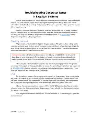
C6200 ApplicationSELCO C6200 C6250400 VAC phase-phase5 A current transformers130/80 kVA Atlas Copco GensetsVolvo Engines Ansaldo alternatorsEDC 4 ECU (Speed Control)Mecc Alte U.V.R.6 Voltage regulatorBarber Colman DYN10794 Speed ControllerMecc Alte U.V.R.6 Voltage regulator
FeaturesImprovedSupplyUniversalSpeed and Volt. Ctrls.(VDC/mA/PWM)ProgrammableSeparateDigital & analogueTrip relaysoutputsCost efficientDesign & enclosureAlternativePlug-inconnectorsAdvancedGrid ParallelingFunctionsSix PI-regulatorsModular100 kBitCAN buswithOn-boarderminationProtection&Controlin one t-in LEDSynchroscopeLots of new featuresAnd functions in FWProgrammableTransformer High current Digital & analogueisolationinputsinputsBuilt-inLoad DependingStart/Stop
C6200 Design
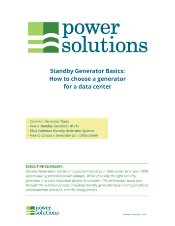
Seamless Integration with PLCDigital inputs with feedback on proceduresC6200 Slave (Semi-Auto)PLC MasterRS485MODBUSDigital outputs to enable/disable proceduresCore GensetControlsProgrammableI/OLogic Controls / Decisions(e.g. Master PMS og Co-Gen Control)
Before going ahead (checklist) Do I have the required experience (training at SELCO)?What is my responsability (customer perceptance)?Will this be a feasible project?Application (Land or Marine)?What about Engine Control logic?Required functionality?If required, what kind of protection?Current Transformers (1A/5A)?How to control speed / frequency?If required, how to control excitation /voltage?Required integration (SCADA etc.)?Is the site ready for my work?Do I have access to all the necessary tools?How to test and prove my system? (customer acceptance)!
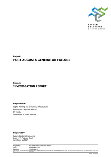
Isolation (Very important!)Common reference (COM) and ground should not beconnected together.Connecting any of the COM connections on the C6200 moduleto ground (or switchboard chassis) may cause instability withinthe system.COMIn a ship installation the hull is considered “ground”.NO!!!As a general rule:1. COM terminals should not be connected to ground,switchboard chassis or ships hull.2. Negative poles of the power supplies should not beconnected to ground, switchboard chassis or ships hull.
Configuration by C6250/S6500C6250 is a convenient substitutefor the PC HyperTerminal. C6250is optional but practical”terminal” for configuration andindication.Configuration TerminalConfiguration Backup/RestoreMultimeterFlush Mount 144 x 96 x 25 mm.RS232(No external supply)CANS6500
Auxillary Supply24 VDC-30% / 20% -The front AUX SUPPLYLED illuminates with asteady green light to indicatethat the supply voltage isOK and within the limits ofsafe operationSupply reference (-) hasconnection to the modulesCOM terminals (samepotential). Auxillary supplyis NOT isolated
Alarm RelayNormally energized Alarm relay.Cannot be reconfigured.De-energizes on system (or system orgeneral) alarm. Will also de-energize ifauxillary supply is lost.Change-over relay with potential freecontacts. 24 VDCCOMMainAlarmSystemWRITE RELAYS ALARMFUNC [SYS, SYSPROT] (SYS)COMCOM is referance
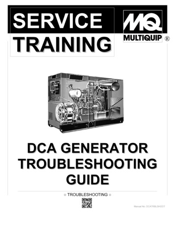
5A / 1A Current MeasurementC6200 variants for 5A and1A available.GeneratorCircuit-breakerS2S2WRITE SYS CTPRIMCUR 100.0S24 x loop 100/5AS1S1S1L2NL1L3ALTERNATORDIESEL / GAS ENGINE(Prime Mover)
AC Voltage MeasurementVoltage measurements on busbar andgenerator are three-phased.Make sure that the phases are connectedcorrectly, as incorrect connection willaffect power factor and loadcalculations.Voltage range is 63 to 690 VACnominal. Voltages above 690 VACrequire external PT’s.Steady lightWhenVoltage OK(Compared to nominal voltage)WRITE SYS NOMVOLT 400.0WRITE SYS PRIMVOLT [63 – 32000] (400)WRITE SYS RATEDFREQ 50.0WRITE SYS VOLTOKWND 10GeneratorCircuit-breakerL2NL1L3ALTERNATORDIESEL / GAS ENGINE(Prime Mover)
General Input/OutputC/B (Feedback) is VERY important!Together with the generator and busbar voltagemeasurements, it tells the C6200 about its ”State ofOperation”:C/B (Feedback)C/B Close BlockUnloadReset AlarmF/V Disable*- Running idle?- Need to Synchronize?- Running in parallel?(Disable frequency & voltage control)The C6200 is BLIND without C/B (Feedback)!*External frequency and voltage controlVolt. In(-1 to 1 VDC)COM is referanceFreq. In(-1 to 1 VDC)
”Size” of the GeneratorCalculating Generator maximum current (GENMAXCUR): PRIMVOLT GENCAP 3 GENMAXCUR Cos 3 GENMAXCUR GENCAP PRIMVOLT3 3 cos Two examples:GENMAXCUR 45.000VA 65 A 400V 3 1.00 3 GENMAXCUR 36.000W 65 A 400V 3 0.80 3 GENMAXCUR WRITE SYS GENMAXCUR [0.5 – 30000] (60.6)130.000W 234.54 A 400V 3 0.8 3
Circuit Breaker Protection TripChange-over relay for opening theBreaker to protect the generator.Relay is normally energized but can beconfigured for normally energizedoperation as well.Trip cause can be signalled onprogrammable outputs as desired.Reverse PowerExcitation LossFrequency DeviationVector Shift 24 VDCWRITE RELAYS PROTTRIP CONTACT [ND, NE] (ND)WRITE IOFUNC RP OUT1WRITE IOFUNC EL OUT2WRITE IOFUNC FD OUT3WRITE IOFUNC VS ORDIESEL / GAS ENGINE(Prime Mover)
Generator ProtectionOver Current and Short CircuitWRITE PROTECT SC ENABLED [YES, NO] (YES)WRITE PROTECT SC LEVEL [100 - 400] (250)WRITE PROTECT SC DELAY [100 - 1000] (100)WRITE PROTECT OC ENABLED [YES, NO] (YES)WRITE PROTECT OC LEVEL [50 - 200] (100)WRITE PROTECT OC DELAY [2.0 – 20.0] (5.0)WRITE IOFUNC SC [OFF, OUTx] (OFF OFF)WRITE IOFUNC OC [OFF, OUTx] (OFF OFF)
Generator ProtectionReverse PowerExcitation LossWRITE PROTECT RP ENABLED [YES, NO] (YES)WRITE PROTECT RP LEVEL [0.0 - -20.0] (-2.0)WRITE PROTECT RP DELAY [2.0 – 20.0] (5.0)WRITE PROTECT EL ENABLED [YES, NO] (YES)WRITE PROTECT EL LEVEL [0 - -150] (-50)WRITE PROTECT EL DELAY [2.0 – 20.0] (5.0)WRITE IOFUNC RP [OFF, OUTx] (OFF)WRITE IOFUNC EL [OFF, OUTx] (OFF)3 Phase Short-Circuit and Over Current by T2500 or Breaker
Generator ProtectionOverloadVoltage MonitoringWRITE PROTECT UV ENABLED [YES, NO] (YES)WRITE PROTECT UV LEVEL [50 - 150] (70)WRITE PROTECT UV DELAY [2.0 – 20.0] (2.0)WRITE PROTECT OV ENABLED [YES, NO] (YES)WRITE PROTECT OV LEVEL [50 - 150] (130)WRITE PROTECT OV DELAY [2.0 – 20.0] (2.0)WRITE IOFUNC OV [OFF, OUTx] (OFF)WRITE IOFUNC UV [OFF, OUTx] (OFF)Frequency MonitoringWRITE PROTECT OL ENABLED [YES, NO] (YES)WRITE PROTECT OL LEVEL [50 - 200] (100)WRITE PROTECT OL DELAY [2.0 – 20.0] (5.0)WRITE IOFUNC OL [OFF, OUTx] (OFF)WRITE PROTECT UF ENABLED [YES, NO] (YES)WRITE PROTECT UF LEVEL [50 - 150] (70)WRITE PROTECT UF DELAY [2.0 – 20.0] (2.0)WRITE PROTECT OF ENABLED [YES, NO] (YES)WRITE PROTECT OF LEVEL [50 - 150] (130)WRITE PROTECT OF DELAY [2.0 – 20.0] (2.0)WRITE IOFUNC OF [OFF, OUTx] (OFF)WRITE IOFUNC UF [OFF, OUTx] (OFF)
Grid monitoringFrequency Deviation/ Rate of Change of Frequency (ROCOF) Disconnection of the generator in case of short time interuptions of the grid. Detection of zero crossings Claculation of frequency Trip of breaker in case change offrequency increases above a certainsetpoint [Hz/s]WRITE PROTECT FD ENABLED [YES, NO] (NO)WRITE PROTECT FD LEVEL [0.0 – 20.0] (2.0)WRITE IOFUNC FD [OFF, OUTx] (OFF)WRITE IOFUNC FD [OFF, OUTx] (OFF)
Grid monitoringVector Shift Disconnection of the generator in case of short time interruptions of the grid. Detection of zero crossings Comparision of expected zerocrossing with actual zero crossing Trip of breaker in case change zerocrossing is shifted more than acertain setpoint [ ] (degrees)WRITE PROTECT VS ENABLED [YES, NO] (NO)WRITE PROTECT VS LEVEL [0.0 – 20.0] (2.0)WRITE IOFUNC VS [OFF, OUTx] (OFF)WRITE IOFUNC VS [OFF, OUTx] (OFF)
Auto-SynchronizationAim is to match frequency (speed),phase (position). Voltage is ”matched”by voltage matching function.C6200 can maintain synchronizationwithout closing the breaker.WRITE AUTOSYNC DBCLOSE [YES, NO] (NO)WRITE AUTOSYNC GAIN [1.0-20.0] (2.0)WRITE AUTOSYNC DELAY [0 – 5000] (10)WRITE AUTOSYNC SYNCTIME [1 - 1000] (60)WRITE AUTOSYNC CBCLOSETIME [1 – 1000] (80)WRITE AUTOSYNC CHKSYNC [YES, NO] (NO)
Circuit Breaker Closeure 24 VDCChange-over relay for closing thegenerator circuit breaker.Relay is normally de-energized.Dead bus closure is TERNATORDIESEL / GAS ENGINE(Prime Mover)
Load Sharing / Parallel LinesLoad balance (active and/or reactive) iscommunicated using a DC-voltagebetween -6 and 6 VDC. Voltage span canbe configured to match e.g. T4800 orT4400 (0-1 / 0-3 VDC).COM is referance.WRITE ACTLS PARLINES VOLTMIN [-6.0 – 6.0] (0.0)WRITE ACTLS PARLINES VOLTMAX [-6.0 – 6.0] (6.0)WRITE REACTLS PARLINES VOLTMIN [-6.0 – 6.0] (0.0)WRITE REACTLS PARLINES VOLTMAX [-6.0 – 6.0] (6.0)C6200#1C6200#2WattCOMVAC6200#3
Unload TripChange-over relay for opening theBreaker after unload of active and/orreactive load.Relay is normally de-energized but canbe configured for normally energizedoperation as well. 24 VDCWRITE RELAYS UNLOADTRIPRELAY CONTACT [ND, NE] (ND)WRITE ACTLS RAMPTIME [1 - 100] (20)WRITE ACTLS CBTRIPLEVEL [1 – 50] (5)WRITE REACTLS RAMPTIME [1 - 100] (20)WRITE REACTLS CBTRIPLEVEL [1 – 50] RDIESEL / GAS ENGINE(Prime Mover)
Load Depending Start/StopNo Master Module Needed!WRITE LOADSTARTSTOP ENABLED YESWRITE LOADSTARTSTOP STARTLEVEL 80WRITE LOADSTARTSTOP STARTDELAY 10WRITE LOADSTARTSTOP STOPLEVEL 60WRITE LOADSTARTSTOP STOPDELAY 10Start GeneratorStop GeneratorStand-by (Next to start)High Load (Pre-warn.)Light Load Cancel(Only Start, no Stop)WRITE IOFUNC GENSTARTIO OFF, OUT1WRITE IOFUNC GENSTOPIO OFF, OUT2WRITE IOFUNC LOADSTARTSTOPENABLE OFFWRITE IOFUNC 1STANDBYINDICATION OUT3WRITE IOFUNC LIGHTLOADCANCEL OFF, IN1WRITE IOFUNC LIGHTLOADINDICATION OUT5WRITE IOFUNC HIGHLOADINDICATION OUT4LightLoad Cancel(Only Start, no Stop)PrioritySelector Switch(1-2-3-4)If no. of Priorities 4:5 IN5 IN8 to COM6 IN6 IN8 to COM7 IN7 IN8 to COMEtc.
Controlling RPM/f by VDCWRITE SYS SPEEDCTRL ENABLED YESWRITE SYS SPEEDCTRL ANAOUT SIGNAL VOLTWRITE SYS SPEEDCTRL ANAOUT VOLTMIN 10.000WRITE SYS SPEEDCTRL ANAOUT VOLTMAX 0.000SPEED FEEDBACK SIGNAL (PULSE TRAIN)FUEL torFuel PumpFlywheelALTERNATORDIESEL / GAS ENGINE(Prime Mover)
Electronic Governorswith Voltage inputsGAC ESD5200(other GAC ESD series are similar in interfacing)External control by DC voltage!C6200 terminal 32 to Governor E (BATT NEGATIVE)C6200 terminal 35 to Governor N (AUX)WRITE SYS SPEEDCTRL ENABLED YESWRITE SYS SPEEDCTRL ANAOUT SIGNAL VOLTWRITE SYS SPEEDCTRL ANAOUT VOLTMIN 10.0WRITE SYS SPEEDCTRL ANAOUT VOLTMAX 0.01. GAIN can affect stability after large fluctuations in load.Make sure that governor control is stable beforeconnecting C6200.2. Readjust SPEED setting after connecting the C6200 tothe AUX input (while generator is running with outconnection to the busbar).3. Potentiometer (SPEED TRIM) input can be used as fallback in conjunction with SELCO E7800.Interfacing to other GAC ESD type governors are similar.
Controlling RPM/f by mAWRITE SYS SPEEDCTRL ENABLED YESWRITE SYS SPEEDCTRL ANAOUT SIGNAL CURWRITE SYS SPEEDCTRL ANAOUT CURMIN 4.000WRITE SYS SPEEDCTRL ANAOUT CURMAX 20.000SPEED FEEDBACK SIGNAL (PULSE TRAIN)FUEL torFuel PumpFlywheelALTERNATORDIESEL / GAS ENGINE(Prime Mover)
Electronic Governorswith Current inputsWoodward 2301 A Speed Control(version with 4-20 mA / 1-5 V speed set)External control by DC current!C6200 terminal 32 to Governor 12 (-)C6200 terminal 34 to Governor 11 ( )WRITE SYS SPEEDCTRL ENABLED YESWRITE SYS SPEEDCTRL ANAOUT SIGNAL CURWRITE SYS SPEEDCTRL ANAOUT CURMIN 4.0WRITE SYS SPEEDCTRL ANAOUT CURMAX 20.04 – 20 mA
Controlling RPM/f by PWMWRITE SYS SPEEDCTRL ENABLED YESWRITE SYS SPEEDCTRL ANAOUT SIGNAL PWMWRITE SYS SPEEDCTRL PWMOUT FREQ 500Open Collector / Amplitude 0-10 VDCV2V3V1COMMON ONTROL UNIT(ECU)SUPPLY PUMPDIESEL / GAS ENGINE(Prime Mover)Open CollectorFrequency: 500 HzAmplitude: 10 VDCDuty Cycle: 10 – 90%(Similar to T7900)3435
Governor Systemswith 500 Hz PWM inputCaterpillar ADEMCaterpillar PEECPWMPWMREFREF -BATTERYExternal control by PWM signal of ADEM!External control by PWM signal of PEEC!C6200 terminal 32 to BATTERY –C6200 terminal 33 to ADEM 10 (RATED SPEED)C6200 terminal 32 to PEEC 19 (BATTERY -)C6200 terminal 33 to PEEC 9 (PRIMARY THROTTLE)WRITE SYS SPEEDCTRL ENABLED YESWRITE SYS SPEEDCTRL ANAOUT SIGNAL PWMWRITE SYS SPEEDCTRL PWMOUT FREQ 500WRITE SYS SPEEDCTRL ENABLED YESWRITE SYS SPEEDCTRL ANAOUT SIGNAL PWMWRITE SYS SPEEDCTRL PWMOUT FREQ 500
Controlling RPM/f by RelaysWRITE IOFUNC SPEEDINC IN2, OUT2WRITE IOFUNC SPEEDDEC IN1, OUT1WRITE SYS SPEEDCTRL ENABLED YESWRITE SYS SPEEDCTRL ANAOUT SIGNAL VOLTWRITE SYS SPEEDCTRL MINPULSE 25024 VDC -ConventionalGovornor(e.g. Woodward UG8)24 VDC - MGovernorRelay ControlV2V3V1FlywheelALTERNATOR -Push-buttons for manualSpeed Control
Relay Control of RPM / VoltPulse Duration (ms)SlopeDeviation in RPM/ Voltage(Hz / Volt)GAIN SlopeDELAY Period TimeMinimum PulseDurationPeriodTimeRELAY INCREASERELAY DECREASE
Fuel Injection Systems (ECU)with Speed Trim Pot-metersVolvo Penta EDC 4 / Deutz EMR1202524B4.5 V 5 VWiper1kSPD SET23GNDExternal control by speed trim potentiometer!1200.5 VAThe two 120 Ohm resistors are for circuit check of the externalthrottle control wiring. Omitting these (going outside 0.5 to 4.5 V)will make teh ECU throw an error code.Voltage between A and 23 0.5 VDC (1.380 RPM)Voltage between B and 23 4.5 VDC (1.620 RPM)0.5 to 4.5 VDC 1.380 to 1.620 RPMC6200 terminal 32 to ECU 23 (GND)C6200 terminal 35 to ECU 24 (WIPER)WRITE SYS SPEEDCTRL ENABLED YESWRITE SYS SPEEDCTRL ANAOUT SIGNAL VOLTWRITE SYS SPEEDCTRL ANAOUT VOLTMIN 0.5WRITE SYS SPEEDCTRL ANAOUT VOLTMAX 4.51.2.3.4.5.Where is the reference for the wiper?What is the lower and upper limits of the wiper?Which voltage span would I need to suit my purpose?Is the ECU configured to external speed control?PID settings of the ECU regulation can affect stabilityafter large fluctuations in load.
Electronic Governorswith Speed Trim Pot-metersCummins EFC(Woodward / Barbar-Colman DYN1)WiperBATTERY-2 78SPDExternal control by speed trim potentiometer!Voltage between 7 and 2 3.5 VDC (600 RPM)Voltage between 9 and 2 7.2 VDC (2.100 RPM)9 10IDLEAUX4.7 to 6.2 VDC 1.000 to 1.860 RPMC6200 terminal 32 to Governor 2 (BATTERY-)C6200 terminal 35 to Governor 8 (WIPER)WRITE SYS SPEEDCTRL ENABLED YESWRITE SYS SPEEDCTRL ANAOUT SIGNAL VOLTWRITE SYS SPEEDCTRL ANAOUT VOLTMIN 4.7WRITE SYS SPEEDCTRL ANAOUT VOLTMAX 6.21.2.3.4.5.Where is the reference for the wiper?What is the lower and upper limits of the wiper?Which voltage span would I need to suit my purpose?RUN SPD settings can affect the settings!GAIN can affect stability after large fluctuations inload.
Six PI-RegulatorsStep by Step tuning.1. Breaker is open (or only generator on busbar)1. Maintain frequency at nominal level byadjusting the speed (RPM) by the governor2. Maintain voltage at nominal level byadjusting the excitation by the AVR2. Breaker is open and busbar is live1. Match voltage to busbar (within VoltageOK Window)2. Auto-synchronice by speed adjustment ongovernor3. Close Breaker when voltage, phase andfrequency deviation is acceptable3. Breaker is closed and busbar is live1. Maintain frequency at 50/60 Hz byadjusting the speed (RPM) by the governor2. Maintain voltage at e.g. 400 VAC byadjusting the excitation by the AVR3. Share the active (Watt) load by adjustingthe speed (RPM) by the governor4. Share the reactive (VA) load by adjustingthe excitation by the AVR1. WRITE FREQSTAB GAIN [1.0 – 20.0] (4.0)WRITE FREQSTAB DELAY [0 – 5000] (10)WRITE VOLTSTAB GAIN [1.0 – 20.0] (1.0)WRITE VOLTSTAB DELAY [0 – 5000] (10)2. WRITE VOLTMATCH GAIN [1.0 – 20.0] (1.0)WRITE VOLTMATCH DELAY [0 – 5000] (10)WRITE AUTOSYNC DBCLOSE [YES, NO] (NO)WRITE AUTOSYNC GAIN [1.0-20.0] (2.0)WRITE AUTOSYNC DELAY [0 – 5000] (10)WRITE AUTOSYNC SYNCTIME [1 - 1000] (60)WRITE AUTOSYNC CBCLOSETIME [1 – 1000] (80)WRITE AUTOSYNC CHKSYNC [YES, NO] (NO)3. WRITE ACTLS GAIN [1.0 – 20.0] (1.0)WRITE ACTLS DELAY [0 – 5000] (10)WRITE ACTLS RAMPTIME [1 - 100] (20)WRITE ACTLS LOADDEV [-100 – 100] (0)WRITE ACTLS CBTRIPLEVEL [1 – 50] (5)WRITE ACTLS PARLINES VOLTMIN [-6.0 – 6.0] (0.0)WRITE ACTLS PARLINES VOLTMAX [-6.0 – 6.0] (6.0)WRITE REACTLS GAIN [1.0 – 20.0] (1.0)WRITE REACTLS DELAY [0 – 5000] (10)WRITE REACTLS RAMPTIME [1 - 100] (20)WRITE REACTLS LOADDEV [-100 – 100] (0)WRITE REACTLS CBTRIPLEVEL [1 – 50] (5)WRITE REACTLS PARLINES VOLTMIN [-6.0 – 6.0] (0.0)WRITE REACTLS PARLINES VOLTMAX [-6.0 – 6.0] (6.0)
Grid Paralleling (Import/Export)GRIDC/B ControlFixed Import(from Grid)Master Freq & Volt ControlIsland / Grid Parallel ModeBusbarPeak Import(from Grid)PowerDistribution(Gens / Grid)G1C/B ControlParallelingSchemeSelectorC/B Control1 2 34Fixed Export(from Gens)G2Load Balance LinesExcess Export(from Gens)WRITE IMPORTEXPORT SCHEME [DISABLED, FIXEDIMPORT, PEAKIMPORT, FIXEDEXPORT, EXCESSEXPORT] (DISABLED)WRITE IMPORTEXPORT VALUE [1 – 100] (25)WRITE IMPORTEXPORT MODE [LS, PF] (LS)
Tie breaker Auto-Sync using T4500Selector Switch PositionTop:Middle:Bottom:Sync. B to ANo Sync.Sync. A to BCOM (C6200)Speed INCR/DECRC/B ControlManualManualG1G2Load Balance LinesManual Speed INCR/DECRG3C/B ControlBusbar BC/B ControlC/B ControlC/B ControlBusbar AG4Load Balance LinesManual Speed INCR/DECR
Programmable Functions WRITE IOFUNC SPEEDINC INx, OUTxWRITE IOFUNC SPEEDDEC INx, OUTxWRITE IOFUNC VOLTINC INx, OUTxWRITE IOFUNC VOLTDEC INx, OUTxWRITE IOFUNC RP OUTxWRITE IOFUNC EL OUTxWRITE IOFUNC FD OUTxWRITE IOFUNC VS OUTxWRITE IOFUNC FREQSTAB INx, OUTx , OUTx (ALARM)WRITE IOFUNC SYNC INx, OUTx, OUTx (ALARM)WRITE IOFUNC ACTRAMPUP INx, OUTx, OUTx (ALARM)FUNC1WRITE IOFUNC ACTLS INx, OUTx, OUTx (ALARM)WRITE IOFUNC VOLTSTAB INx, OUTx , OUTx (ALARM)WRITE IOFUNC VOLTMATCH INx, OUTx, OUTx (ALARM)FUNC2WRITE IOFUNC REACTRAMPUP INx, OUTx, OUTx (ALARM)WRITE IOFUNC REACTLS INx, OUTx, OUTx (ALARM)WRITE IOFUNC PFCTRL INx, OUTx, OUTx (ALARM)WRITE IOFUNC GENSTARTIO INx, OUTxWRITE IOFUNC GENSTOPIO INx, OUTxWRITE IOFUNC LOADSTARTSTOPENABLE INxWRITE IOFUNC 1STANDBYINDICATION OUTxWRITE IOFUNC LIGHTLOADCANCEL INxWRITE IOFUNC LIGHTLOADINDICATION OUTxWRITE IOFUNC HIGHLOADINDICATION OUTxWRITE IOFUNC FIXEDIMP INxWRITE IOFUNC PEAKIMP INxWRITE IOFUNC FIXEDEXP INxWRITE IOFUNC EXCESSEXP INxOR relation between functions sharing inputs and/or outputs!WRITE IOFUNC FVDISABLE OUTx
Comparing configuration fileshttp://winmerge.org/
5 A current transformers. Transformer isolation Programmable Digital & analogue inputs Protection & Control in one box Built-in LED Synchroscope Programmable Digital & analogue outputs Separate . Core Genset Controls Logic Controls / D