Transcription
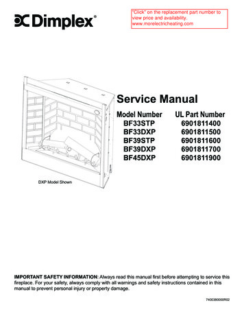
"Click" on the replacement part number toview price and availability.www.morelectricheating.comService ManualModel NumberBF33STPBF33DXPBF39STPBF39DXPBF45DXPUL Part 811900DXP Model ShownIMPORTANT SAFETY INFORMATION: Always read this manual first before attempting to service thisfireplace. For your safety, always comply with all warnings and safety instructions contained in thismanual to prevent personal injury or property damage.7400380000R02
TABLE OF CONTENTSOperation. . . . . . . . . . . . . . . . . . . . . . . . . . . . . . . . . . . . . . . . . . . . . . . . . . . . . . . . . . . 3Exploded Parts Diagram. . . . . . . . . . . . . . . . . . . . . . . . . . . . . . . . . . . . . . . . . . . . . . . 6Wiring Diagram - STP Models . . . . . . . . . . . . . . . . . . . . . . . . . . . . . . . . . . . . . . . . . . 7Wiring Diagram - DXP Models . . . . . . . . . . . . . . . . . . . . . . . . . . . . . . . . . . . . . . . . . . 8Switch Replacement - Main On/Off Power; Purifier/Heat; Mode Selector. . . . . . . . . . . . . . . . . . . . .9Light Harness Replacement. . . . . . . . . . . . . . . . . . . . . . . . . . . . . . . . . . . . . . . . . . . 10LED Driver Board Replacement - DXP Models Only . . . . . . . . . . . . . . . . . . . . . . . 10Flicker Motor & Rod Replacement. . . . . . . . . . . . . . . . . . . . . . . . . . . . . . . . . . . . . . . 11Blower Replacement . . . . . . . . . . . . . . . . . . . . . . . . . . . . . . . . . . . . . . . . . . . . . . . . . 11Secured in Wall. . . . . . . . . . . . . . . . . . . . . . . . . . . . . . . . . . . . . . . . . . . . . . . . . . . . . . . . . . . . . . . . . . . . . . . . 11Removable from Wall . . . . . . . . . . . . . . . . . . . . . . . . . . . . . . . . . . . . . . . . . . . . . . . . . . . . . . . . . . . . . . . . . . . 12High Temperature Cutout Replacement . . . . . . . . . . . . . . . . . . . . . . . . . . . . . . . . . 12Secured in Wall. . . . . . . . . . . . . . . . . . . . . . . . . . . . . . . . . . . . . . . . . . . . . . . . . . . . . . . . . . . . . . . . . . . . . . . . 12Removable from Wall . . . . . . . . . . . . . . . . . . . . . . . . . . . . . . . . . . . . . . . . . . . . . . . . . . . . . . . . . . . . . . . . . . . 13Element Replacement. . . . . . . . . . . . . . . . . . . . . . . . . . . . . . . . . . . . . . . . . . . . . . . . 13Secured in Wall. . . . . . . . . . . . . . . . . . . . . . . . . . . . . . . . . . . . . . . . . . . . . . . . . . . . . . . . . . . . . . . . . . . . . . . . 13Removable from Wall . . . . . . . . . . . . . . . . . . . . . . . . . . . . . . . . . . . . . . . . . . . . . . . . . . . . . . . . . . . . . . . . . . . 14Voltage Selector Switch Replacement. . . . . . . . . . . . . . . . . . . . . . . . . . . . . . . . . . . 14Secured in Wall. . . . . . . . . . . . . . . . . . . . . . . . . . . . . . . . . . . . . . . . . . . . . . . . . . . . . . . . . . . . . . . . . . . . . . . . 14Removable from Wall . . . . . . . . . . . . . . . . . . . . . . . . . . . . . . . . . . . . . . . . . . . . . . . . . . . . . . . . . . . . . . . . . . . 14BFRC-KIT Remote Control Receiver Installation/Replacement . . . . . . . . . . . . . . 15WRCPF-KIT Wall Controller Installation/Replacement . . . . . . . . . . . . . . . . . . . . . 15BF Plug Kit Replacement (BFPLUGE). . . . . . . . . . . . . . . . . . . . . . . . . . . . . . . . . . . 16Assembly Component Pictures. . . . . . . . . . . . . . . . . . . . . . . . . . . . . . . . . . . . . . . . 17Troubleshooting Guide. . . . . . . . . . . . . . . . . . . . . . . . . . . . . . . . . . . . . . . . . . . . . . . 19Always use a qualified technician or service agency to repair this fireplace.! NOTE: Procedures and techniques that are considered important enough to emphasize.CAUTION: Procedures and techniques which, if not carefully followed, will result in damage to theequipment. WARNING: Procedures and techniques which, if not carefully followed, will expose the user to therisk of fire, serious injury, or death.2www.dimplex.com
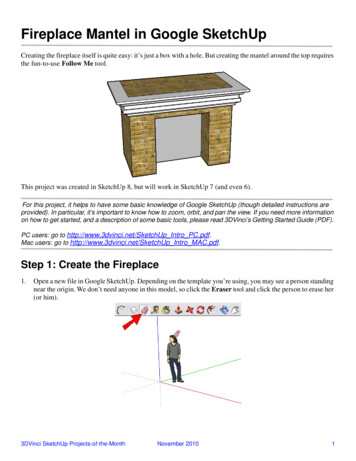
OperationManual Controls - Without Remote OptionThe fireplace can be controlled by the manual switcheslocated on the fireplace (Figure 1).Figure 1Voltage Selector SwitchOver Heat IndicatorMode Selector SwitchMain On/Off SwitchMain Power Switch - Energizes firebox and flame.Mode Selector Switch:Select “o” for flame onlySelect “-“ for Purifire /flame (no heat)Select “ ” for heat/Purifire /flameVoltage Selector Switch ARNING: Ensure that the incoming power supplyWvoltage matches the setting of the voltage selectorswitch.! NOTE: The voltage selector switch is located insidethe exhaust panel on the top right hand corner (Figure1).CAUTION: When changing the voltage selector switchfrom 240 volts to 120 volts ensure that the power supplyis turned off.! NOTE: Carefully insert a flat head screwdriver insidethe exhaust panel to change the switch from 240 volts(230 position) to 120 volts (115 position).Resetting the Temperature Cutout SwitchThe heater on this fireplace is protected with a safety deviceto prevent overheating. Should the heater overheat, a redlight (Figure 1) will be activated and an automatic cut outwill turn the heater off. The heater will re-activate once theheater has cooled. The overheat cutout will be triggered ifthe filter is dirty.CAUTION: If you need to continuously reset the heater,disconnect power and call Dimplex customer service at1-888-DIMPLEX (1-888-346-7539).Manual Controls - With Remote Accessory(Hand held or Wall Mounted)The fireplace with the Remote Option has the same manualcontrols with the addition of the Remote Control Receiver(BFRC-KIT). The Remote Receiver Switch Board which willwork in conjunction with the original controls.The remote control operation can be adjusted, dependingon the season and desired effects, by toggling the mainmode selector switch built into the fireplace. The positionof the switch will dictate the available functions that theremote control will cycle through.! NOTE: The original controls will override all othersettings, both the Mode Selector Switch as well as theMain On/Off Switch. (Figure 2)A. Manual Selection SwitchSwitches the operation of the fireplace between thedifferent modes of the fireplace: OFF (center): Makes the unit inoperable. MANUAL (top): All functions of the fireplace arecontrolled by the On and Off buttons as described above(Figure 2B & C). REMOTE (bottom): All functions of the fireplace arecontrolled by the Remote Control.B. Off ButtonPressing this button toggles sequentially through the threelevels of the fireplace. (Only when the selection switch is inthe Manual Position) Mode Selector Set at “O”: Only Flame Effect at all 3levels. Mode Selector Set at “--”: Pressing once activatesLevel 1 - Flame effect only, two and three timesactivates Level 2 - Flame effect and Purifire . Mode Selector Set at “ ”: Pressing once activatesFigure 2Original VersionCDFE2010 UpdateDBCEBAF3
Level 1 - Flame effect only, twice activates Level 2 Flame effect and Purifire , three times activates Level3 - Flame effect, Purifire and heat.C. On ButtonPressing this button at any time will shut the unit off.D, E & F LED IndicatorsDepicts which of the three (3) levels the fireplace iscurrently operating at: Level 1 3-, Level 2 -or Level.Optional Remote Control OperationThe BFRC-KIT is supplied with a radio frequency remotecontrol. This remote control has a range of approximately50 feet (15.25 m), it does not have to be pointed at thefireplace and can pass through most obstacles (includingwalls). It is supplied with one of hundreds of independentfrequencies to prevent interference with other units.! NOTE: Before attempting any operation with theremote, pull the plastic insulator strip out from betweenthe remote casing and battery cover (Figure 3).The remote control operates the fireplace levelssequentially. The level is increased every time the ONbutton on the remote control is pressed. The fireplace canbe turned off at any point by pressing the OFF button on theremote control.! NOTE: The Mode Selector Switch on the originalmanual controls needs to be set to “ ” to have fullfunctionality of the fireplace. (Figure 2):The flame effect is turned on and the first redLevel 1indicator light is activated.Level 2: The flame effect remains on, the Purifire isactivated. (Heater remains off): The flame effect remains on, the Purifire isLevel 3activated and the heater turns on.Remote Control Initialization/ReprogrammingIf the remote control or receiver has been replaced or theremote does not seem to be operating the fireplace, followthese steps to initialize/reprogram the remote control andreceiver:1. Ensure that power is supplied through main servicepanel.Figure 3OnButtonOff ButtonPlasticStripBatteryCoverBattery mustbe recycled ordisposed ofproperly. Check withyour Local Authority orRetailer for recyclingadvice in your area.2. Access the manual controls, (remove the glass doorsif applicable) pull the right hand steel curtain to theoutside of the unit.3. Locate manual controls.4. Move the 3-position switch to “Remote”, on newermodels only.5. Activate the main power switch, the red Level 1Indicator Light may flash. (Figure 2-D)6. Press and hold the On button on the manual controls(Figure 2-C) for five (5) seconds. The Level 1 IndicatorLight(Figure 2-D) will then flash for 10 seconds.7. Within the 10 seconds press the ON button located onthe hand held remote control (Figure 3) or any buttonon the wall mounted controller. This will synchronizethe remote control and receiver.Battery ReplacementTo replace the battery:1. Slide battery cover open on the remote control(Figure 3).2. Install one (1) 12-Volt (A23) battery in the batteryholder.3. Close the battery cover.Optional Wall Mounted Remote Operation! NOTE: For button/display references see Figure 4.1. Room Temperature - Displays current ambienttemperature in the room.2. Set Temperature - Displays and controls the heaterto the temperature at which the thermostat is currently setto. Press 8 to lower the thermostat and press 9 to raisethe thermostat. Pressing both 8 and 9 together will togglebetween Celsius and Fahrenheit.3. Flame Effect Icon - The flame icon will flicker if andwhen the Flame Effect is turned on. Press 11 to turn theFlame Effect on, and press 10 to turn the Flame Effect off.4. Purifire Icon - The display arrows for the Purifire will cycle when turned on. Press 13 to turn the Purifire function on, and press 12 to turn Purifire off.5. Heat Off Indicator - This function manually overridesthe thermostat control and prevents the fireplace’s heaterfrom coming on.To do this, press 8 to decrease Set Temperature to anytemperature below 0o C or 32o F. To reactivate heat from“HEAT OFF” setting, press 9 to increase the thermostatSet Temperature. The Set Temperature will be displayedstarting at 21o C (70o F), replacing the “HEAT OFF” icon.6. Function Lock Indicator - Enabling this function willlock out the Wall Switch Remote Control so as to preventthe current settings from being changed. To Enable, press8, 9, and 10 sequentially. To disengage, press 8, 9 and10 sequentially again. The Indicator icon will be displayedwhen enabled.7. RF Code Function and Change Procedure - In4www.dimplex.com
the event that the Wall Switch Remote Control does notwork properly with the receiver due to interference fromadditional wireless signals, this function will allow the RFcode to be changed.To enable this function, press 9 and 12 together. “CODE”will appear on the display for five (5) seconds and theRF code will change automatically. Repeat procedure asneeded to find a code that operates the fireplace withoutinterference.Re-initialization of the Wall Switch Remote Control willneed to take place with receiver after a new code has beenactivated. See initialization instructions.14. Low Battery IndicatorWhen displayed, the indicator will signal that the batteriesare low and should be replaced. To further extend batterylife, the LED backlighting is turned off when the Low BatteryIndicator is displayed.Other Functions6 Hour Sleep Timer - This feature ensures all functions areturned off six hours after any last button has been pressed.To turn this feature on and off press 9, 11, 10, and 8sequentially.When activated, “6 Hr” will display for 5 seconds while therest of the LCD remains blank. For the duration of the 6hour delay, all functions remain working until the 6 hourtime delay runs out. The Set Temperature and RoomTemperature icons will alternately display their settings andthe “6 Hr” icon display. After 6 hours have passed and allfunctions are turned off, “6 Hr” will flash until any button ispressed.! NOTE: If any button is pressed while this function isenabled, the 6 hour timer will start over for another 6hour period.If / when deactivated (pressing the same sequence ofbuttons again), “- Hr” will display for five (5) seconds.Battery ReplacementTo replace the battery:1. Remove the decora cover from the electrical boxand press the wall remote inward until the push-lockreleases from the mounting box.1. Remove the wall remote from the mounting box andslide battery cover open.2. Install two (2) 1.5V (AAA) battery in the battery holder.3. Close the battery cover.4. Reinstall the wall control into mounting box.Figure 467512891011121341.2.3.4.5.6.7.DisplayRoom TemperatureSet TemperatureFlame EffectPurifire Heat Off IndicatorFunction Lock IndicatorRF Code Function Indicator314Additional Optional Wall MountedControlsThe fireplace can be installed with wall-mountedcontrols. These controls include wall switchesand thermostats. (See installation guide forspecific installation details)A. Wall Mounted SwitchesThis model may be installed such that a wallmounted switch activates the flame effect and awall mounted heater switch activates the heater.A wall-mounted switch can also be installed tooperate the heater independent of the flame.B. Wall Mounted ThermostatThis unit may be installed with a wallmounted thermostat which can adjust the heattemperature to your individual requirements.Turn the thermostat control clockwise all the wayto turn on the heater. When the room reachesthe desired temperature, turn the thermostatknob counter clockwise until you hear a click.Leave in this position to maintain the roomtemperature at this setting. For additional heat,turn the thermostat clockwise until you hearthe click again and the heater will turn on. Toturn the heater off, turn the thermostat counterclockwise all the way, and/or turn the manualheater switch on the unit to the OFF position,“O”.Operation8. Set Temperature Down9. Set Temperature Up10. Flame Off11. Flame On12. Purifire Off13. Purifire On14. Low Battery Indicator5
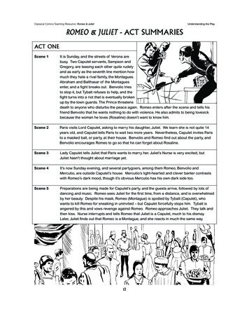
"Click" on the replacement part number toview price and availability.www.morelectricheating.comExploded Parts Diagram7681813202112416119171021CATALOGUE NUMBERUL PART NUMBERREPLACEMENT PART1. LOG SET2. REFLECTOR ROD3. GROMMET4. FLICKER MOTOR5. FLICKER CONNECTOR6. BLOWER MOTOR7. HEATER ELEMENT8. CUTOUT9. VOLTAGE SELECTOR (6 WIRE)VOLTAGE SELECTOR (3 WIRE)10. MAIN ON/OFF SWITCH11. HEAT SWITCH (--/O ORIGINAL)3 POSITION PURIFIRE SWITCH12. PARTIALLY REFLECTIVE GLASS13. EXTRUSION14. STEEL CURTAIN15. STEEL CURTAIN ROD16. LIGHT HARNESS ASSEMBLY17. SMART LOG DRIVER18. PURIFIRE FILTER REPLACEMENT19. SWING DOOR HARDWARE KIT20. FULL DOOR HARDWARE KIT21. REMOTE CONTROL KIT22. WALL MOUNTED REMOTE KIT23. THERMOSTAT24. PLUG KIT FOR 120V WALL 0320100RP--------- VERIFY 6 WIRE OR 3 WIRE AT TIME OF ORDER -KITWRCPF-KITTS321W (SINGLE POLE), TD322W (DOUBLE POLE)BFPLUGE* 5900161000RP no longer available, 5900161100RP with brick finish can be used as a substitute6www.dimplex.com
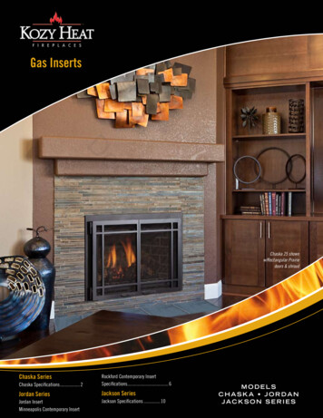
Wiring Diagram - STP Models7
Wiring Diagram - DXP Models8www.dimplex.com
Switch Replacement - Main On/Off Power;Purifier/Heat; Mode SelectorTools required: Phillips head screwdriverFlat head screwdriver! NOTE: Depending on the Modification Level (MOD.)of your fireplace you will have at least two (or a variation) ofthese types of switches: MAIN ON/OFF POWER; PURIFIRE/HEAT; MODE SELECTOR, all of which are located inthe same area in the firebox and can be replaced followingthe same instructions below. WARNING: If the fireplace was operating prior toservicing allow at least 10 minutes for light bulbs andheating elements to cool off to avoid accidental burningof skin. WARNING: Disconnect circuit power before attempting any maintenance or cleaning to reduce the risk ofelectric shock or damage to persons.1. Open the steel curtains (remove glass doors if applicable).2. Remove the 2 screws from the log set retaining platealong the front of the log set and remove the retainingplate.3. Pull the rear edge of the log set forward by graspingthe ember bed by the sides, pull firmly until the rear tabpops out from under the back ledge, then lift the logsout. (Figure 5)! IMPORTANT: Only handle the log-set by the plasticember-bed, not the logs themselves.! NOTE: Log-set fits tightly into firebox. Some forcemay be necessary to remove.4. Disconnect the log set LED wire harness from unit.(DXP MODELS ONLY)5. Locate the removable bracket on the lower right sideof the fireplace and remove the 2 mounting screwslocated to the left of the switches. (Figure 6)6. Remove the bracket - turn the back edge toward thelight bulb about 1/2” (12.7mm) then lift straight up.! NOTE: For Models with Remote Control ReceiverInstalled the Plug Connector will have to be disconnected.Figure 6RemovableBracketTo do this, squeeze the tabs on either side.7. Reach hand into the opening and locate the switch tobe replaced.8. Depress the retainer clips on both sides of the switchand push the switch out of the top.9. Disconnect the wiring connections noting their originallocations.! NOTE: Using a flat head screwdriver gently pry between the end of the connector and the switch to releasethe wires.10. Properly orient the new switch and reconnect all of thewiring connections.11. Reassemble in the reverse order as above.! NOTE: When re-inserting the log-set, insert the frontedge first then push the backside of the log-set down untilthe rear tab snaps under the back partially reflective glassledge and the logs are resting against the partially reflectiveglass.Figure 5MirrorEmber BedAssemblyBack LedgeRear TabFront Edge9
Light Harness ReplacementTools required: Phillips head screwdriver.Wire cutters/strippers WARNING: If the fireplace was operating prior toservicing allow at least 10 minutes for light bulbs andheating elements to cool off to avoid accidental burningof skin. WARNING: Disconnect circuit power before attempting any maintenance or cleaning to reduce the risk ofelectric shock or damage to persons.1. Open the steel curtains (remove glass doors if applicable).2. Remove the 2 screws from the log set retaining platealong the front of the log set and remove the retainingplate.3. Pull the rear edge of the log set forward by graspingthe ember bed by the sides, pull firmly until the rear tabpops out from under the back ledge, then lift the logsout. (Figure 5)! IMPORTANT: Only handle the log-set by the plasticember-bed, not the logs themselves.! NOTE: Log-set fits tightly into firebox. Some forcemay be necessary to remove.4. Disconnect the log set LED wire harness from unit.(DXP MODELS ONLY)5. Remove all lower light bulbs.6. Remove the 4 retaining screws on the lower light assembly retaining plate and pull it away from the lowerpanel.7. Cut the blue and white light harness wires from theold harness at the first socket, which lead inside thefirebox. Strip the ends leading inside the firebox by approximately a ½” (12.7 mm).8. Remove the socket rings that hold the sockets to thelight assembly retaining plate by unscrewing the ringscounter clockwise.9. Remove the old sockets and replace with the newsockets and socket rings.10. Cut the metal ferrules off the end of the blue and whitewires from the new light harness and strip them by approximately a ½” (12.7mm).11. Using a wire-nut, connect the 2 matching wire endsfrom the old and new harness, matching up the colors(1-blue to 1-blue / 1-white to 1-white).! NOTE: Connection to the terminal block can only beaccessed through additional disassembly therefore an additional electrical junction is recommended in the bottomarea.12. Reassemble in the reverse order as above.! NOTE: When re-inserting the log-set, insert the frontedge first then push the backside of the log-set down untilthe rear tab snaps under the back partially reflective glassledge and the logs are resting against the partially reflectiveglass.LED Driver Board Replacement - DXPModels OnlyTools Required: Phillips head screwdriverNeedle nose pliersFlat head screwdriver WARNING: If the fireplace was operating prior toservicing allow at least 10 minutes for light bulbs andheating elements to cool off to avoid accidental burningof skin. WARNING: Disconnect circuit power before attempting any maintenance or cleaning to reduce the risk ofelectric shock or damage to persons.1. Open the steel curtains (remove glass doors if applicable).2. Remove the 2 screws from the log set retaining platealong the front of the log set and remove the retainingplate.3. Pull the rear edge of the log set forward by graspingthe ember bed by the sides (handle the log set only bythe ember bed and not the logs) and pulling firmly untilthe rear tab pops out from under the back ledge, thenlift out. (Figure 5)! IMPORTANT: Only handle the log-set by the plasticember-bed, not the logs themselves.! NOTE: Log-set fits tightly into firebox. Some forcemay be necessary to remove.4. Disconnect the log set LED wire harness from unit.5. Remove the light assembly retaining plate by removing4 lower light bulbs and the retaining plate screws. Setthe retaining plate and light bulbs aside.6. Reach hand into the opening created by removing thelight assembly retaining plate and locate the LED driverboard mounted on the lower right side on the backpanel.7. Remove the wires attached to the board noting theiroriginal location.! NOTE: Using a flat head screwdriver gently pry between the end of the connector and the switch to releasethe wires.8. Remove the driver board off the 4 mounting clips (oneon each corner of the board), by squeezing the tips ofthe mounting clips with needle nose pliers. Squeezethem just enough to pull the board off. These clips willbe re-used to secure the new board.9. Line up the mounting holes on the new board to theclips and press the new board in place.10. Install wires on new board in the original configuration.11. Re-assemble in reverse order as above.! NOTE: When re-inserting the log-set, insert the frontedge first then push the backside of the log-set down untilthe rear tab snaps under the back partially reflective glassledge and the logs are resting against the partially reflectiveglass.10www.dimplex.com
Flicker Motor & Rod ReplacementTools Required: Phillips head screw driver¼” (5.5 mm) ratchet/socket or wrench WARNING: If the fireplace was operating prior toservicing allow at least 10 minutes for light bulbs andheating elements to cool off to avoid accidental burningof skin. WARNING: Disconnect circuit power before attempting any maintenance or cleaning to reduce the risk ofelectric shock or damage to persons.1. Open the steel curtains (remove glass doors if applicable).2. Remove the 2 screws from the log set retaining platealong the front of the log set and remove the retainingplate.3. Pull the rear edge of the log set forward by graspingthe ember bed by the sides (handle the log set only bythe ember bed and not the logs) and pulling firmly untilthe rear tab pops out from under the back ledge, thenlift out. (Figure 5)! IMPORTANT: Only handle the log-set by the plasticember-bed, not the logs themselves.! NOTE: Log-set fits tightly into firebox. Some forcemay be necessary to remove.4. Disconnect the log set LED wire harness from unit.(DXP MODELS ONLY)5. Remove the 4 lower light bulbs and the light assemblyretaining plate screws. Set the retaining plate and lightbulbs aside.6. Reach hand into the opening created by removing thelight assembly retaining plate and locate the flickerassembly, the assembly runs horizontally across themiddle of the unit parallel with the floor (cannot be seenfrom the front opening). The assembly is secured withtwo brackets, one on either side.7. Remove the flicker assembly mounting bracket on theright side (the same side as the controls), using a ¼”(5.5mm) hex head ratchet/socket or wrench.8. Remove the flicker rod from the flicker assembly bypulling the rubber channel section of the rod (locatedon the left side of the bracket) away from the flickermotor.! NOTE: Once the screw holding the flicker assemblymounting bracket has been removed you can also turn themotor and remove the left end of the flicker rod, to removethe rubber channel. When doing this be careful not to bendthe flicker rod as when the unit is reassembled the flamemay not function properly.9. Rotate the flicker motor assembly down releasing theangled mounting tab on the bracket from the rear panelof the fireplace.! NOTE: In order for the mounting tab to release fromthe rear panel, the flicker assembly mounting bracketneeds to be rotated a complete 90 down. Cutting of thewire tie wraps may also be required to move wires out ofthe way.10. Disconnect the wiring connections from the terminalblock noting their original locations.a) If the new flicker motor has 3 wires: disconnect thewiring connections noting their original locations.b) If the new flicker motor has 2 wires: disconnect thewiring connections and the capacitor, install the 2 wiresin the two holes where the capacitor was installed.11. Remove the two mounting screws on either side of themotor and replace with the new one.12. Properly orient the new motor and reconnect all of thewiring connections.13. Reassemble in the reverse order as above.! NOTE: Be sure to secure the flicker rod to the flickermotor prior to securing flicker motor assembly bracket toflame panel. Use wire ties to ensure wires do not come incontact with moving parts.! NOTE: When re-inserting the log-set, insert the frontedge first then push the backside of the log-set down untilthe rear tab snaps under the back partially reflective glassledge and the logs are resting against the partially reflectiveglass.Blower ReplacementSECURED IN WALLTools Required: Philips head screwdriverFlat head screwdriverNeedle nose pliers WARNING: If the fireplace was operating prior toservicing allow at least 10 minutes for light bulbs andheating elements to cool off to avoid accidental burningof skin. WARNING: Disconnect circuit power before attempting any maintenance or cleaning to reduce the risk ofelectric shock or damage to persons.1. Open the steel curtains (remove glass doors if applicable).2. Remove the 2 screws from the log set retaining platealong the front of the log set and remove the retainingplate.3. Pull the rear edge of the log set forward by graspingthe ember bed by the sides, pull firmly until the rear tabpops out from under the back ledge, then lift the logsout. (Figure 5)! IMPORTANT: Only handle the log-set by the plasticember-bed, not the logs themselves.! NOTE: Log-set fits tightly into firebox. Some forcemay be necessary to remove.4. Disconnect the log set LED wire harness from unit.(DXP MODELS ONLY)5. Release the steel curtains from the side panels byopening the retainers on the sides of the fireplace using11
needle nose pliers.6. Remove the steel curtains by lifting up on the curtainmounting rod releasing it from the side mounting tab,and pulling out.7. Remove the 2 filter retaining screws and remove thefilter and retaining plate.8. Remove the 10 mounting screws from inside the firebox that secures the interior top panel and remove theheater cover.9. Remove the 3 heater assembly mounting screws fromunderneath the top panel along the front.10. Lower the heater assembly so that the 3 support tabs,in the top panel, can be easily released.11. Remove wiring connections from blower motor notingtheir original locations.! NOTE: Using a flat head screwdriver gently prybetween the end of the connector and the blower/motor torelease the wires.
Voltage Selector Switch. WARNING: Ensure that the incoming power supply voltage matches the setting of the voltage selector switch.! NOTE: The voltage selector switch is located inside the exhaust panel on the top right hand corner (Figure 1). CAUTION: When changing the voltage selector switch from 240 volt