Transcription
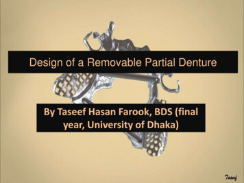
Design of a Removable Partial DentureBy Taseef Hasan Farook, BDS (finalyear, University of Dhaka)
Denture Design: A planned visualization of theform and extent of a dental prosthesisarrived at after a study of all factors involved- GPT
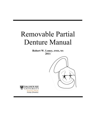
Kennedy’s Classification of partiallyedentulous jaw Classification I- bilateral edentulous area situatedposterior to natural teeth Classification II- unilateral edentulous area situatedposterior to natural teeth Classification III- edentulous space bounded on bothside by natural teeth Classification IV- A single, but bilateral edentulous arealocated anterior to the natural teethApplegate‘s 8 rules are used in diagnosing a caseaccording to Kennedy’s classification
Types of partially edentulous jaw According to the Classificationby Edward Kennedy in 1923:
Basic ConsiderationsBiomechanics at play within the oral cavity must betaken into consideration and the denture designmust be made in accordance, to counteract themechanical forces/stress acting within the oralcavity.Forces to consider: 1. Vertical – Displacing- Dislodging forces2. Horizontal forces3. Torsion
Biomechanics and Types of RPDMost common mechanical forces at play:1. Lever principle (all Kennedy Class I and II cases)2. Inclined principle (all rest and retainers)3. Wheel and axle principle (rotation)the prosthesis constructed can either be:1. Tooth supported- (all Kennedy Class III dentures)2. Tissue supported (Kennedy Class I & II dentures)
Wheel & Axle PrincipleLever and Fulcrum PrincipleInclined plane principle
Tooth Supported prosthesis(Kennedy Class III)Tissue Supported ProsthesisKennedy Class I & II)
Biological factors to consider duringdesign Length of edentulous spanType of oral mucosaQuality of ridge supportClasp design – (type, length, flexibility,material used) Occlusal harmony
Initial Step is Surveying of the cast To determine path of insertion To mark the height of contour Mark undercuts otherwise not visible to thenaked eyeSurvey Lines: line produced on a cast of a tooth bya surveyor or scriber marking the greatestheight of contour in relation to the chosen pathof insertion of a planned restoration- GPT
Survey LinesTypes of survey lines: 1. High2. Medium3. Low4. Diagonal
1. Path of insertion Kennedy Class I case: may have multiple paths ofinsertion. A single path obtained by additionalguiding planes on the lingual surface Kennedy Class II: Path of insertion depends onthe modification space and their guiding plane Kennedy Class III: Single path of insertiondepending on the proximal abutment teeth Kennedy Class IV: Single path of insertion
Factors influencing Path of insertion Retentive undercutsInterferenceGuiding planeDenture BaseGuiding plane: Two or more vertically parallel surfacesof abutment teeth so oriented as to direct the path ofplacement of removable partial denture- GPTUse short guiding planes for Class I & II cases, use longguiding planes for Class III and IV cases
2. Height of ContourLine encircling a tooth designating its greatestcircumference at a selected position – GPTThe area below the height of contour is apotential undercut and if feasible, can be usedfor designing the retentive components of anRPD.
3. UndercutsThe area enclosed by the vertical drop andhorizontal surface of any given structure.LingualUndercut
After Surveying, the next step is toDESIGN THE COMPONENTS of the RPDParts: Major connectors Minor Connectors Rests Retainers Denture baseKennedy Class II modification I cast partial denture
Major connectorsBasic Design principles: The borders should be 6mm (maxillary) and 3mm(mandibular) away from the marginal gingiva The borders should be parallel to the gingivalmargin The metal framework should cross the gingivalmargin only at 90 degree (right angle) and crossthe palate in a straight line Anterior border of maxillary major connectorsshould not lie on the crest of the palatal rugae
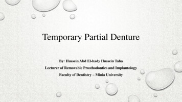
Maxillary major connectors: (and theiruses) Single posterior palatal bar (Kennedy Class III)Palatal Strap (bilateral short span Class III)Palatal plate (Kennedy class I)Antero-posterior palatal bars ( Class II and IV)Horse shoe shaped plate ( Class I and II)Complete palate (Kennedy Class I)
PALATAL BARPALATAL PLATEPALATAL STRAPHORSESHOE PLATEANTERO-POSTERIORPALATAL STRAPCOMPLETE PALATE
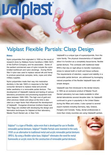
Mandibular major connectors Lingual barLingual PlateDouble lingual bar/ Kennedy barSublingual barMandibular cingulum barLabial bar
LINGUAL BARLINGUAL PLATEDOUBLE LINGUAL BARSUBLINGUAL BAR
Major Connectors of ChoiceFor maxillary arches: broad palatal plate connectorModifications:1. L-beam priniciple2. Circular configuration3. Strut configurationCircularconfigurationFor mandibulararches, lingualplate withretainers can helpdistribute stress.
Minor ConnectorsThese are the connecting links between the majorconnector and clasps, retainers and rests.Basic Design principles: Broad bucco-lingually, thin mesio-distally Triangular cross-section with thickest portion near thelingual line angle If not placed on the abutment teeth, the connectorshould be placed in the embrasure. Should NEVER be placed on the convex lingual surface The area to hold the connector should be devoid ofundercuts and parallel to path of insertion Mandibular distal extension should cover 2/3rd thelength of the edentulous ridge
Types of minor connectors Lattice work Meshwork Bead, wire or nail headLATTICE WORKMESHWORKNAIL HEAD TYPE
Finish LineThe term denotes the junction between the acrylic denture baseand the major connector.Types: Internal finish line: metal to tissue surface External finish line: acrylic to metal surfaceInternal finish lineExternal Finish line
Finish Line Design Acrylic around lattice or meshwork minorconnectors should be smooth and presentwith internal and external finish lines Bead type minor connectors require onlyexternal finish line
RestsRest: rigid stabilizing extension of a partial denturewhich contacts a remaining tooth/teeth todissipate vertical and horizontal forcesTypes:1. External2. Internal––––Occlusal restIncisal restCingulum restLingual rest
Rest seatThat portion of natural tooth or a castrestoration of a tooth selected or prepared toreceive an occlusal, incisal, lingual, internalor semiprecision rest - GPT
Design of an occlusal rest seat Triangular shape with apex at the centre of thetooth and base at the marginal ridge ½ buccolingual width 1/3 mesiodistal width Angle between floor of the prosthesis andproximal surface of tooth 90 degree 0.5mm thick at thinnest point and 1-1.5 mmthick at margin.
Design of lingual and cingulum rest 2.5-3mm mesiodistal length2mm labiolingual width1.5mm deepV-shaped notch- labial inclination parallel to labialsurface, lingual inclination perpendicular to the labialincline Apex of the V directed incisally
Direct retainer Component of a removable partial denturethat is used to retain and preventdislodgement consisting of a clasp, assemblyor precision attachment – GPTTypes:Extra-coronalOcclusal Approach- Aker’s ClaspIntra-coronalInternal AttachmentExternal AttachmentGingival Approach- Bar ClaspStud attachmentBar attachmentSpecial attachment
Design of a clasp The retentive arm terminal 1/3rd should beflexible to engage undercuts The proximal 1/3rd of the retentive arm to beplaced above the height of contour The rigid components are to be placed in thenon retentive areas of the tooth The retentive part must make use of theretentive undercuts present on the tooth
Design of claspSelection of clasp material according to thebuccolingual width of the undercut: (moreflexible material is required to facilitate insertionof the RPD into deeper undercuts) 0.010 inch undercut- cast chrome alloy 0.015 inch undercut- gold and its alloys 0.020 inch undercut- wrought wire-The longer the clasp arm, greater the flexibility.-The clasp arm should be tapered towards the tip
Types of Clasp Circumferential Clasp/ Aker’s Clasp– Simple circlet (NOT used for distal extension cases)– Reverse circlet (used in distal extension cases)– Multiple circlet (used for abutment with weakperiodontal support)– Modified crib clasp (used in Kennedy Class II and IIIwithout any modifications)– Ring clasp (used in distolingual undercuts andlingually tipped molars)
Other types of circumferential clasps Fish hook clasp (used when undercut is adjacentto an edentulous area) Onlay clasp (used when abutment teeth arebelow occlusal level. Thus the onlay restoresocclusal harmony while the clasp providesretention) Combination clasp (wrought wire retentive armand cast wire bracing arm) Vertical reciprocal, horizontal retentive arm claspVRHR-(Used in posterior teeth with high surveylines)
Bar clasps T-clasp (used in distal extension cases. ShouldNOT be used in terminal abutments withundercuts facing away from the edentulousspace) Modified T clasp (used in canine andpremolars for better aesthetics) Y-clasp (used for high heights of contour) I-clasp- (used on distobuccal surface of caninewith only tip in contact with the tooth
Occlusal Approach:Circumferential claspGingival Approach:Bar type of clasps
Clasp design configurationQuadrilateral Configuration: Usuallyseen in Kennedy Class III with amodification on the opposite side ofthe archTripod Configuration: Usually seen inKennedy Class II arches
Clasp design configurationBilateral configuration:Used in case of KennedyClass I cases
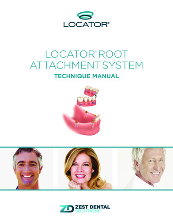
I-bar system (RPI system) Modified type of roach clasp designed toreduce tooth contact R –RestP -Proximal plateI -I-bar clasp.
I-bar system (RPI system)
I-bar system (RPI system)
Modifications in the RPI system RPA system- When the i-bar is replaced by anAker’s clasp. Mesial rest modification Proximal modification– Design modification I, II, IIIMod. IMod. IIMod. III
Fulcrum Line An imaginary line around which a partialdenture tends to rotate- GPT This is a line joining the two posterior mostrests
Indirect retainer Part of a removable partial denture which assiststhe direct retainers in preventing displacement ofthe distal extension denture bases by functioningthrough lever action on the opposite side of thefulcrum- GPT
Design of Indirect retainer Ideally, the indirect retainer should be locatedat a point perpendicular to the midpoint ofthe fulcrum line Should be placed as far away from thefulcrum line as possible Should generally be made of rigid material.(Flexibility loses efficacy) Inclined or weak abutment teeth should NOTbe used.
The indirect retainer should beperpendicular to the fulcrumlineThe indirect retainer should be asfar away from the fulcrum line aspossible
Types of indirect retainer1. Auxiliary occlusal rest –-Used on 1st premolars bilaterally forKennedy Class I cases-Used on 1st premolar of opposite side forKennedy Class II cases2. Canine Extension- When premolars must actas a primary abutment3. Canine rest
Types of indirect retainer4. Continuous lingual bar/plate retainers –Used for Kennedy Class I and II cases. The barshould be placed above the middle 1/3rd ofthe tooth to prevent unwanted toothmovement5. Rugae support6. Direct-indirect retention (from thereciprocating arm anterior to fulcrum line)7. Indirect retention from the major connectors
When to use indirect retainer? Kennedy Class I: indirect retainers arenecessary and should be placed as far awayfrom fulcrum line as possible Kennedy Class II: indirect retainer on bothsides of the arch Kennedy Class III: indirect retainer is NOTrequired
Denture Base Types:– Metallic– Non Metallic (acrylic, plastic, etc.)– Combination
Design of denture base Should have long flanges to resist horizontalforces Distal extension should extend onto theretromolar pad or cover the entire tuberosity Since metallic dentures can be made rigid in thinsections, mandibular dentures benefit greatly bythe thin rigid plate. Maxillary dentures benefit from non metallicdenture materials due to the aesthetic formfactor although lack the good thermalconductivity that metallic dentures offer.
Tooth selection for the denture(According to Deepak Nallaswamy) Anterior teeth replacement–––––Acrylic teethPorcelain teethMetal teeth with facingTube teethReinforced acrylic ponticPosterior teeth replacement-porcelain teeth- metal teeth- acrylic teeth- metal teeth with acrylic window
In summary Design consideration depends on a variety offactors. Design of a removable partial denture changeswith respect to some form of edentulousclassification. We prefer to follow theclassification proposed by Edward Kennedy.
Kennedy Classification I Direct retainer: essential. The position of theundercut determines the type of retainer (i.egingival/occlusal approach) Clasp: 2 clasps on terminal abutmentsbilaterally. This follows bilateral configuration Rest: to be prepared on tooth with maximumsupport Indirect retainer: 2 retainers are needed Major connector: Palatal Plate, complete palate,horse shoe palates, lingual plate, cingulum plate.
Kennedy Classification I Design
Kennedy Classification I Design
Kennedy Classification II Direct retainer: essential. The position of the undercutdetermines the type of retainer (i.e gingival/occlusalapproach) Clasp: 3 retentive clasps are required, 1 clasp on theedentulous side and 2 on the dentulous side. Shouldfollow Tripod configuration Rest should be placed on tooth with maximum support Indirect retainer: 1 retainer on the dentulous side issufficient Major connector: horse shoe shaped palatal connector,antero-posterior palatal bar, lingual bar,
Kennedy Classification II modification 1Design
Kennedy Classification II modification 1Design
Kennedy Classification III Direct retainer: position of undercut is NOTcritical in designing the prosthesis sincedamage to abutment is minimal Clasp: 4 clasps should be placed forquadrilateral design in case of modification ofclass III. Indirect retainer: not needed Major connector: single posterior palatal bar,palatal strap, lingual bar
Kennedy Classification III, Modification 1 Design
Kennedy Classification III, Modification 1 Design
Kennedy Classification IV In case of short edentulous spans, the needfor retainers and clasps are very limited. In case of long span edentulous areas,– 4 clasps can be placed for quadrilateralconfiguration– Indirect retainer to be placed posterior to thefulcrum line
Kennedy Classification IV Design
Reference A textbook of prosthodontics, Deepak Nallaswamy,reprint 2005. McCracken’s removable partial Prosthodontics, 11thedition. Principles of designing in Removable partial denture,Shebin Abraham, online presentation, uploaded on11/2/2016, slideshare.net. Designing removable partial dentures, Dr Ting LingChang, UCLA, online presentation, ffofr.org. Presentations by Indian dental academy Pictures from the internet
Design of a Removable Partial Denture By Taseef Hasan Farook, BDS (final year, University of Dhaka) Denture Design: A planned visualization of the form and extent of a dental prosthesis arrived at after a study of all fac