Transcription
Emerson FB1100 Flow Computer Instruction ManualD301752X012July 2021Emerson FB1100 Flow ComputerInstruction ManualRemote Automation Solutions
Emerson FB1100 Flow Computer Instruction ManualD301752X012July 2021Device Safety Considerations Reading these InstructionsBefore operating the device, read these instructions carefully and understand their safety implications. In some situations,improperly using this device may result in damage or injury. Keep this manual in a convenient location for future reference.Note that these instructions may not cover all details or variations in equipment or cover every possible situation regardinginstallation, operation, or maintenance. Should problems arise that are not covered sufficiently in the text, immediatelycontact Customer Support for further information. Protecting Operating ProcessesA failure of this device – for whatever reason -- may leave an operating process without appropriate protection and could resultin possible damage to property or injury to persons. To protect against this, you should review the need for additional backupequipment or provide alternate means of protection (such as alarm devices, output limiting, fail-safe valves, relief valves,emergency shutoffs, emergency switches, etc.). Contact Remote Automation Solutions for additional information. Returning EquipmentIf you need to return any equipment to Remote Automation Solutions, it is your responsibility to ensure that the equipmenthas been cleaned to safe levels, as defined and/or determined by applicable federal, state and/or local law regulations orcodes. You also agree to indemnify Remote Automation Solutions and hold Remote Automation Solutions harmless from anyliability or damage which Remote Automation Solutions may incur or suffer due to your failure to ensure device cleanliness. Grounding EquipmentGround metal enclosures and exposed metal parts of electrical instruments in accordance with OSHA rules and regulations asspecified in Design Safety Standards for Electrical Systems, 29 CFR, Part 1910, Subpart S, dated: April 16, 1981 (OSHA rulings arein agreement with the National Electrical Code). You must also ground mechanical or pneumatic instruments that includeelectrically operated devices such as lights, switches, relays, alarms, or chart drives.Important: Complying with the codes and regulations of authorities having jurisdiction is essential to ensuring personnelsafety. The guidelines and recommendations in this manual are intended to meet or exceed applicable codes and regulations.If differences occur between this manual and the codes and regulations of authorities having jurisdiction, those codes andregulations must take precedence. Protecting from Electrostatic Discharge (ESD)This device contains sensitive electronic components which be damaged by exposure to an ESD voltage. Depending on themagnitude and duration of the ESD, it can result in erratic operation or complete failure of the equipment. Ensure that youcorrectly care for and handle ESD-sensitive components.System TrainingA well-trained workforce is critical to the success of your operation. Knowing how to correctly install, configure, program,calibrate, and trouble-shoot your Emerson equipment provides your engineers and technicians with the skills and confidenceto optimize your investment. Remote Automation Solutions offers a variety of ways for your personnel to acquire essentialsystem expertise. Our full-time professional instructors can conduct classroom training at several of our corporate offices, atyour site, or even at your regional Emerson office. You can also receive the same quality training via our live, interactiveEmerson Virtual Classroom and save on travel costs. For our complete schedule and further information, contact the RemoteAutomation Solutions Training Department at 800-338-8158 or email us at education@emerson.com.ii
Emerson FB1100 Flow Computer Instruction ManualD301752X012July 2021ContentsSection 1:Introduction11.11.21.3Safety Labels . 3Features . 3Central Processing Unit (CPU) . 41.3.1 Memory . 41.4 Explosion-proof Enclosure . 41.4.1 Physical Security . 51.5 I/O. 61.6 Power Options. 61.7 Communications . 71.8 Human-Machine Interface (HMI) Module . 71.9 FBxWifi Communications . 81.10Software Tools . 91.11Autonomous Measurement Mode. 91.12RoHS2 Compliance . 9Section 2:Installation112.12.22.32.42.52.6Hazardous Locations . 11Environmental Specifications . 12Required Tools . 12Site Considerations . 13General Wiring Guidelines . 14Front or Rear End Caps . 142.6.1 Removing/Replacing Retaining Clamp on End Caps . 142.6.2 Removing the Front or Rear End Caps . 152.6.3 Replacing the Front or Rear End Caps. 162.7 Mounting the Enclosure . 162.7.1 Bolting Considerations . 172.7.2 O-rings with Flange Adapters. 182.7.3 Direct Mount . 192.7.4 Indirect Mount . 192.7.5 Rotating the Housing . 212.8 Grounding the Device . 222.9 Terminal Plate . 232.10Power Modes . 242.10.1 Low Power Mode . 242.10.2 Standard Power Mode . 252.10.3 Notes on Battery Life . 262.11Connecting Power. 262.11.1 Connecting DC Power . 272.11.2 Connecting Battery Power . 272.12Installing the Optional Solar Panel . 282.12.1 Attach Mounting Hardware to the Solar Panel . 292.12.2 Mounting the Solar Panel (Integral Mount) . 302.12.3 Mounting the Solar Panel (Remote Mount) . 32Contentsiii
Emerson FB1100 Flow Computer Instruction ManualD301752X012July 20212.12.42.12.5Connecting Solar Power . 33Adjusting the Optional Solar Panel Tilt Angle . 342.13Connecting Communication Ports . 352.13.1 Connecting to COM1 . 362.13.2 Connecting to COM2 and COM3 . 372.14Connecting the RTD . 402.15Wiring the Digital Output . 41Section 3:3.13.23.3Section 4:4.14.24.34.44.54.64.7Operation43Powering Up/Powering Down the Device . 43Establishing Communications . 433.2.1 Communicating with the SCADA Host . 433.2.2 Communicating with a Laptop Using One of the Serial Ports . 443.2.3 Communicating with a Laptop Wirelessly with FBxWifi . 45Communicating using the HMI Module . 45Service and Troubleshooting49Returning the Unit for Repairs . 50Interpreting the Status LEDs . 51Switch and Buttons . 53Removing/Replacing the HMI Module . 53Replacing the Main Battery Pack . 54Removing/Replacing the SRAM Battery . 57Upgrading System Firmware . 58Appendix A: Special Instructions for Class I Division 2 Locations61Appendix B: Special Instructions for Class I Division 1 Locations65Appendix C: ATEX Non-Sparking Zone 2 Certifications71Appendix D: ATEX Flame-Proof Zone 1 Certifications73Appendix E: Autonomous Mode Requirements75Index77ivContents
Emerson FB1100 Flow Computer Instruction ManualD301752X012July 2021Section 1: IntroductionThis section covers the following topics: Safety Labels Features Central Processing Unit (CPU) Explosion-proof Enclosure I/O Power Options Communications Human-Machine Interface (HMI) Module FBxWifi Communications Software Tools Autonomous Measurement Mode RoHS2 ComplianceThe Emerson FB1100 Flow Computer measures pressure, differential pressure, and temperaturefor a single meter run of natural gas. This manual describes how to install and configure theEmerson FB1100 Flow Computer hardware.For information on using the FBxConnect configuration software, see the online help thataccompanies FBxConnect.Introduction1
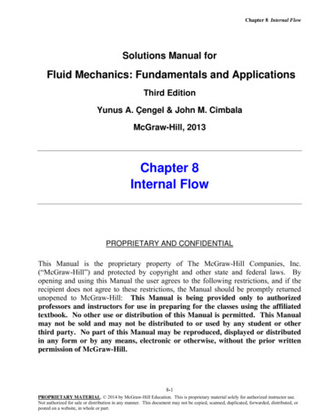
Emerson FB1100 Flow Computer Instruction ManualD301752X012July 2021Figure 1-1: FB1100 Flow Computer12345672HMI moduleFront end cap (cover)Data plateRear end cap (cover)Conduit fittingsEnclosureSensor moduleIntroduction
Emerson FB1100 Flow Computer Instruction ManualD301752X012July 2021Safety LabelsThis product may display safety label(s) to identify potential hazards. The same types of noticesappear within the documentation. Whenever you see an exclamation point (!) enclosed within atriangle (shown to the left), consult the documentation for additional safety information about thehazard and how to avoid it. The labels used are:DANGERMAY CAUSE DEATHObserve all precautionary signs posted on the equipment.Failure to do so may result in death or serious injury to personnel.WARNINGDANGER TO PERSONNEL AND EQUIPMENTObserve all precautionary signs posted on the equipment.Failure to do so may result in injury to personnel or cause damage to the equipment.CAUTIONMAY CAUSE INJURY TO PERSONNEL OR DAMAGE EQUIPMENT.Observe all precautionary signs posted on the equipment.Failure to do so may result in injury to personnel or cause damage to the equipment.SAFETY FIRSTGeneral instructions and safety reminders.FeaturesThe FB1100 Flow Computer includes the following key features:Introduction Enclosure suitable for use in Class I Division 1 explosion proof and Ex db Zone 1 flame-proofenvironments Enclosure suitable for use in Class I Division 2 non-incendive and Ex nA Zone 2 non-sparkingenvironments Integral multi-variable sensor for measurement of Pressure (P) and Differential Pressure (DP) Connections for customer-supplied resistance temperature detector (RTD) for measurementof temperature (T) Single digital output3
Emerson FB1100 Flow Computer Instruction ManualD301752X012July 2021 Power from a DC power supply, a lithium battery, or an optional lead acid battery/solar panelcombination Serial communication options for RS-232, RS-485 (2-wire), RS-485/422 (4-wire). HMI module with optional display and back light for local operator interaction Optional Wi-Fi transceiver (802.11 b/g) for field technician to access the flow computerfrom a laptop without physical cable connection Application software supports AGA3, AGA8, ISO 5167, ISO 6976, and API 21.1 calculations inU.S., metric, or other natural gas standard units Support for one-year autonomous measurement without external power (lithium batteryoption)Central Processing Unit (CPU)The flow computer’s CPU is a NXP Kinetis K61 series CPU with an ARM Cortex M4 processorthat operates at 4 to 60 MHz depending on the power mode. The CPU runs the Micrium operatingsystem.1.3.1MemoryThe flow computer includes both static and flash memory.Table 1-1: MemoryMemoryUsage8 MB SRAMHolds in-use configuration, current state of all variables128 MB FlashHolds firmware image, historical logs, configuration backup (if saved to flash),and the executing programExplosion-proof EnclosureThe FB1100 Flow Computer includes an explosion-proof enclosure made of either aluminum orstainless steel. The enclosure consists of the main housing, two threaded covers, and four conduitentry points.The four conduit entry points are ¾ in NPT pipe threaded holes that permit entry of field conduitfor I/O and communication wiring. ATEX installations use a ¾ in NPT to M20 thread reducer.Unused apertures shall be closed with suitable blanking elements.The FB1100 Flow Computer can operate in an unprotected outdoor environment. Wiring for I/O,communications, and power enters the enclosure through the four conduit fittings withappropriate protective seals and connects to the terminal plate.The front end cap (cover) provides a viewing window for the HMI module. You can access theterminal plate by removing the rear end cap (cover).4Introduction
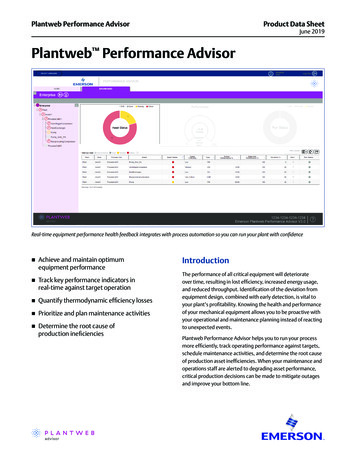
Emerson FB1100 Flow Computer Instruction ManualD301752X012July 2021The FB1100 Flow Computer has North American certification for Class I Division 1 Groups C and D(explosion proof) and Class I Division 2 Groups A, B, C and D (non-incendive) hazardous locations ornon-hazardous locations. See Appendix A and Appendix B for more information.The FB1100 Flow Computer has European certification for EExd Zone 1 (flame-proof) and EExdZone 2 (non-sparking) hazardous locations or non-hazardous locations. See Appendix C andAppendix D for more information.Details on certification information are included on the data plate screwed to the top of theenclosure.1.4.1Physical SecurityThe flow computer end caps include retaining clamps for ATEX/IEC applications. In addition, if localregulations require it, you can wire a tamper-resistant seal using the tie holes located in the frontand rear end caps, and in the coupling screws.Figure 1-2: Retaining Clamps and Tie Holes for Tamper-resistant Seals123IntroductionRetaining clamp (For ATEX & IEC approved products only)Tie holes in end capsTie holes in coupling screws5
Emerson FB1100 Flow Computer Instruction ManualD301752X012July 2021I/OThe flow computer comes with base I/O from both the CPU and the built-in multi-variable (MV)sensor. Base I/O consists of: Pressure (P) input from the MV sensor Differential pressure (DP) input from the MV sensor Connections for temperature (T) input from a customer-supplied RTD Single general purpose digital output (DO) - for use with an odorizer or other devicePower OptionsYou can power the flow computer using an external DC input, an internal battery, or an internalrechargeable battery connected to a solar panel.ImportantUse only batteries supplied with the flow computer or sold by Emerson Remote AutomationSolutions as spare parts for this flow computer. If you substitute a battery you obtain elsewhere youwill void your certification unless it is the identical part from the same manufacturer as thatsupplied with the flow computer from Emerson.Table 1-2: Power Options6OptionUsageExternal DC PowerSupply5.7 Vdc to 30 Vdc external supply (Max power at 10 watts)Lead Acid Battery Pack 6.0 Vdc4.5AhNot suitable with ATEX or IECEx applicationsCan be optionally charged by a 6-watt solar panelLithium Battery Pack10 Vdc41 Ah (approximate)Not suitable with ATEX or IECEx applicationsRequired when using autonomous measurement modeIn autonomous measurement mode allows operation for one year Introduction
Emerson FB1100 Flow Computer Instruction ManualD301752X012July 2021CommunicationsThe flow computer includes three serial communication ports. The serial ports allowcommunication using DNP3, Modbus, BSAP, and ROC protocols.Table 1-3: Serial PortsPortTypeCOM1 COM2 COM3 UseSerial communicationsSoftware-selectable for RS-232, RS485 (2-wire), RS-485/422 (4-wire)operation4-wireRS-232, RS-485 (2-wire), RS-485/422 (4-wire)communication to host or other devices. 4wire used with external radio.Serial communicationsSoftware-selectable for RS-232, orRS-485 (2-wire) operation2-wireRS-232 or RS-485 (2-wire) communication tohost or other devices.Serial communicationsSoftware-selectable for RS-232, orRS-485 (2-wire) operation2-wireRS-232 or RS-485 (2-wire) communication tohost or other devices.Human-Machine Interface (HMI) ModuleThe flow computer includes an HMI module with an optional liquid crystal display (LCD) for localoperator access to the device. The LCD, if present, shows a series of menus that sequentially displaythe current values of particular process variables. A configuration parameter in FBxConnectdetermines whether you must log in first to view the menus. If required, you log in by selectingalphanumeric characters by scrolling through a list until you select the correct character.The HMI module includes four LEDs to provide status information. Units with the display includefour infrared (IR) buttons for operator interaction.To conserve power, the HMI module enters sleep mode after a period of inactivity. Sleep modedisables FBxWifi communication. In FBxConnect, you can configure the number of minutes ofinactivity triggering sleep mode through the LCD Sleep Time parameter. Setting this parameter to0 disables sleep mode which keeps the HMI module on but uses significantly more power.Introduction7
Emerson FB1100 Flow Computer Instruction ManualD301752X012July 2021Figure 1-3: HMI Module with LCDFigure 1-4: HMI Module without LCDNoteIf your flow computer does not include the LCD option, you still have the status LEDs and a single IRbutton for waking up the device (shown in Figure 1-4).FBxWifi CommunicationsThe flow computer has an optional Wi-Fi transceiver (FBxWifi) that enables you to connect via alaptop or tablet from some small distance away.This capability allows an operator to potentially remain outside the hazardous location and stillcommunicate with the flow computer. The operator's laptop must have Wi-Fi capability, line-ofsight access to the HMI module, and must be loaded with FBxConnect configuration software.Once connected, the operator can view process values, edit configuration parameters, and collectlogs.NoteThe FBxWifi electronics reside inside the HMI module. The HMI module must be awake to useFBxWifi communications You can wake it up manually by holding a finger against the front coverglass over the Hold to Wake button (the left-most button) for typically from five to ten seconds.8Introduction
Emerson FB1100 Flow Computer Instruction ManualD301752X012July 2021Software ToolsFBxConnect provides a series of wizards that allow you to perform configuration activities for theflow computer. You connect a PC running FBxConnect to the flow computer using one of thecommunication ports or through a wireless connection. You can then: Set parameters within your application Configure I/O channels Specify the serial communication method for a port (RS-232 to RS-485) as needed View or collect audit trail information such as alarm, event, or historical logs Update system firmwareAutonomous Measurement ModeYou can configure the FB1100 Flow Computer to operate as a low power measurement device thatoperates independently for one year. In this autonomous measurement mode, the flow computeroperates similarly to earlier generation chart recorders, collecting data from non-critical, low-flowapplications and storing it for later retrieval.Autonomous measurement mode supports collection of data from the multi-variable sensor andRTD only. This mode requires the lithium battery pack; no external power supply is required.You can interact with the device through the HMI module's infrared buttons or through a laptoprunning FBxConnect. To maintain low power consumption for the battery, using this mode limitsyou to 30 minutes of interaction per month.See Appendix E for more information.RoHS2 ComplianceDevice with Integral MVS:RoHS (2) EU Directive 2011/65/EU: This product may be considered out-of-scope when used forthe intended design purpose in a Large Scale Fixed Installation (LSFI).Consult https://www.emerson.com/compliance for up-to-date product information.Introduction9
Emerson FB1100 Flow Computer Instruction ManualD301752X012July 202110Introduction
Emerson FB1100 Flow Computer Instruction ManualD301752X012July 2021Section 2: InstallationThis section covers the following topics: Hazardous Locations Environmental Specifications Required Tools Site Considerations General Wiring Guidelines Front or Rear End Caps Mounting the Enclosure Grounding the Device Terminal Plate Power Modes Connecting Power Installing the Optional Solar Panel Connecting Communication Ports Connecting the RTD Wiring the Digital OutputThe flow computer ships from the factory fully assembled, except for the optional solar panelassembly.2.1Hazardous LocationsThe housing for the FB1100 Flow Computer is an explosion-proof case designed to operate inhazardous locations.For North America the FB1100 Flow Computer has certifications for Class I, Division 1 (Groups C &D) explosion-proof, Class I Division 2 (Groups A, B, C & D) non-incendive, and non-hazardouslocations only. Appendix A contains special information for Class I Division 2 installations; Appendix Bcontains special information for Class I Division 1 installations.For Europe the FB1100 Flow Computer has certifications for Ex db Zone 1 flame-proof and for Ex nAZone 2 non-sparking installations and non-hazardous locations only. Appendix C contains specialinformation for Ex nA Zone 2 installations; Appendix D contains special information for Ex db Zone 1installations.All certifications are listed on the data plate located on the top of the device.Installation11
Emerson FB1100 Flow Computer Instruction ManualD301752X012July 20212.2Environmental SpecificationsThis section summarizes the environmental specifications for the device. For full details, refer tothe product data sheet FB1100 Flow Computer (D301781X012).Table 2-1: Environmental SpecificationsSpecificationRangeAmbient Temperature-40 C to 80 C (-40 F to 176 F) - no battery, C1D1/C1D2-40 C to 80 C (-40 F to 176 F) - lead acid battery, C1D1/C1D2-40 C to 80 C (-40 F to 176 F) - lithium battery, C1D1/C1D2-40 C to 80 C (-40 F to 176 F) - no battery, ATEX/IEC Ex db-40 C to 80 C (-40 F to 176 F) - no battery, ATEX/IEC Ex nAMaximum Process Connection120 C (248 F)Temperature2.3Humidity5% to 95% non-condensingVibration2g over 10 to 150 Hz; 1g over 150 to 200 HzRequired ToolsCertain tools and equipment are required for installing and servicing the flow computer.Table 2-2: Required Tools12ToolUseTorque wrenchFor bolting/mounting the flow computer2.5 mm hexagonal wrenchFor manipulating rotation set screw3 mm hexagonal wrenchFor screw for M4 x 0.7 end cap retaining clamp(ATEX required)9/16 in hexagonal wrenchFor installing/removing ¾ in NPT conduit plugs1 1/16 in combination wrenchFor installing/removing ¾ in NPT to M20 threadreducer (ATEX required)#1 Phillips-head screwdriverFor screws on HMI module#2 Phillips-head screwdriverFor screws on other modules and boards1/8 inch flat-head screwdriverFor 5.08 mm pitch terminal block connectionsLaptop PC running Field Tools with FBxConnectconfiguration softwareFor software configurationInstallation
Emerson FB1100 Flow Computer Instruction ManualD301752X012July 20212.4Site ConsiderationsThe flow computer must reside in an accessible location for configuration and service. Refer to thedimensional drawings for information on the space required. Ensure the installation location provides easy access to the HMI module. If your unit includes the optional solar panel, ensure the installation location providessufficient space to mount the solar panel and adequate sunlight to charge the battery. If your unit includes the optional FBxWifi ensure the installation location provides line-ofsight access to the transceiver.Figure 2-1: FB1100 Flow Computer Dimensions – Multivariable SensorInstallation13
Emerson FB1100 Flow Computer Instruction ManualD301752X012July 20212.5General Wiring GuidelinesThe flow computer’s pluggable terminal blocks use compression-type terminals thataccommodate wire between 28 and 12 AWG.2.6 When making a connection, insert the bare end of the wire (approx. 1/4" max) into the clampadjacent to the screw and secure the screw. To prevent shorts, ensure that no bare wire is exposed. Allow some slack in the wire while making terminal connections. Slack makes the wires moremanageable and helps minimize mechanical strain on the terminal blocks. Use twisted pair, shielded and insulated cable for communication and I/O wiring to minimizesignal errors caused by electromagnetic interference (EMI), radio frequency interference(RFI), and transients. When using shielded cable, ground all shields at only one point in theappropriate system. This prevents circulating ground current loops that can cause signalerrors.Front or Rear End CapsThe flow computer includes two threaded covers (end caps). The front end cap includes a windowfor viewing the HMI module; the rear end cap provides access to the terminal plate for power andI/O wiring.2.6.1Removing/Replacing Retaining Clamp on End CapsFor flameproof ATEX/IEC applications, each end cap includes a retaining clamp which screws downto prevent the end cap from being unscrewed.Figure 2-2: Front End Cap with Retaining Clamp Fitted12314End CapScrewRetaining ClampInstallation
Emerson FB1100 Flow Computer Instruction ManualD301752X012July 2021Figure 2-3. Retaining Clamp in PlaceTo loosen or tighten the screw, use a 3mm hexagonal wrench. When tightening, torque to 12 in-lbs(1.4 N m).Figure 2-4. Retaining Clamp and Screw2.6.2Removing the Front or Rear End CapsDANGEREXPLOSION HAZARD: Never remove end cap(s) in a hazardous location. Removing end cap(s) in ahazardous location could result in an explosion.NoteIf you need more leverage place a long screwdriver or other appropriate tool across the twonotches in the end cap to act as a pry bar (see Figure 2-5).Figure 2-5: Removing or Tightening the End Cap with Long ScrewdriverInstallation1.Remove the retaining clamp (if present). (See Section 2.6.1.)2.Grasp the end cap (front or rear).15
Emerson FB1100 Flow Computer Instruction ManualD301752X012July 2021Figure 2-6: Front (lef
The EmersonFB1100 Flow Computer measures pressure, differential pressure, and temperature for a single meter run of natural gas. This manual describes how to install and configure the Emerson FB1100 Flow Computer hardware. For information on using the FBxConnect configuration s