Transcription
Chapter 8 Internal FlowSolutions Manual forFluid Mechanics: Fundamentals and ApplicationsThird EditionYunus A. Çengel & John M. CimbalaMcGraw-Hill, 2013Chapter 8Internal FlowPROPRIETARY AND CONFIDENTIALThis Manual is the proprietary property of The McGraw-Hill Companies, Inc.(“McGraw-Hill”) and protected by copyright and other state and federal laws. Byopening and using this Manual the user agrees to the following restrictions, and if therecipient does not agree to these restrictions, the Manual should be promptly returnedunopened to McGraw-Hill: This Manual is being provided only to authorizedprofessors and instructors for use in preparing for the classes using the affiliatedtextbook. No other use or distribution of this Manual is permitted. This Manualmay not be sold and may not be distributed to or used by any student or otherthird party. No part of this Manual may be reproduced, displayed or distributedin any form or by any means, electronic or otherwise, without the prior writtenpermission of McGraw-Hill.8-1PROPRIETARY MATERIAL. 2014 by McGraw-Hill Education. This is proprietary material solely for authorized instructor use.Not authorized for sale or distribution in any manner. This document may not be copied, scanned, duplicated, forwarded, distributed, orposted on a website, in whole or part.
Chapter 8 Internal FlowLaminar and Turbulent Flow8-1CSolutionWe are to compare pipe flow in air and water.AnalysisReynolds number is inversely proportional to kinematic viscosity, which is much smaller for water than forair (at 25 C, air 1.562 10-5 m2/s and water 0.891 10-3/997 8.9 10-7 m2/s). Therefore, for the same diameter andspeed, the Reynolds number will be higher for water flow, and thus the flow is more likely to be turbulent for water.DiscussionThe actual viscosity (dynamic viscosity) is larger for water than for air, but the density of water is somuch greater than that of air that the kinematic viscosity of water ends up being smaller than that of air.8-2CSolutionWe are to compare the wall shear stress at the inlet and outlet of a pipe.AnalysisThe wall shear stress w is highest at the tube inlet where the thickness of the boundary layer is nearlyzero, and decreases gradually to the fully developed value. The same is true for turbulent flow.DiscussionWe are assuming that the entrance is well-rounded so that the inlet flow is nearly uniform.8-3CSolutionWe are to define and discuss hydraulic diameter.AnalysisFor flow through non-circular tubes, the Reynolds number and the friction factor are based on the hydraulicdiameter Dh defined as Dh 4 Acwhere Ac is the cross-sectional area of the tube and p is its perimeter. The hydraulicpdiameter is defined such that it reduces to ordinary diameter D for circular tubes since D h 4 Ac 4 D 2 / 4 D. DpDiscussionHydraulic diameter is a useful tool for dealing with non-circular pipes (e.g., air conditioning and heatingducts in buildings).8-2PROPRIETARY MATERIAL. 2014 by McGraw-Hill Education. This is proprietary material solely for authorized instructor use.Not authorized for sale or distribution in any manner. This document may not be copied, scanned, duplicated, forwarded, distributed, orposted on a website, in whole or part.
Chapter 8 Internal Flow8-4CSolutionWe are to define and discuss hydrodynamic entry length.AnalysisThe region from the tube inlet to the point at which the boundary layer merges at the centerline iscalled the hydrodynamic entrance region, and the length of this region is called hydrodynamic entry length. The entrylength is much longer in laminar flow than it is in turbulent flow. But at very low Reynolds numbers, Lh is very small(e.g., Lh 1.2D at Re 20).DiscussionThe entry length increases with increasing Reynolds number, but there is a significant change in entrylength when the flow changes from laminar to turbulent.8-5CSolutionWe are to discuss why pipes are usually circular in cross section.AnalysisLiquids are usually transported in circular pipes because pipes with a circular cross section can withstandlarge pressure differences between the inside and the outside without undergoing any significant distortion.DiscussionPiping for gases at low pressure are often non-circular (e.g., air conditioning and heating ducts in buildings).8-6CSolutionWe are to define and discuss Reynolds number for pipe and duct flow.AnalysisReynolds number is the ratio of the inertial forces to viscous forces, and it serves as a criterion fordetermining the flow regime. At large Reynolds numbers, for example, the flow is turbulent since the inertia forces arelarge relative to the viscous forces, and thus the viscous forces cannot prevent the random and rapid fluctuations of thefluid. It is defined as follows:(a) For flow in a circular tube of inner diameter D:Re (b) For flow in a rectangular duct of cross-section a b:where Dh aVD bRe VD h 4 Ac4ab2ab is the hydraulic diameter.p2( a b) ( a b)DDiscussionSince pipe flows become fully developed far enough downstream, diameter is theappropriate length scale for the Reynolds number. In boundary layer flows, however, the boundary layergrows continually downstream, and therefore downstream distance is a more appropriate length scale.8-3PROPRIETARY MATERIAL. 2014 by McGraw-Hill Education. This is proprietary material solely for authorized instructor use.Not authorized for sale or distribution in any manner. This document may not be copied, scanned, duplicated, forwarded, distributed, orposted on a website, in whole or part.
Chapter 8 Internal Flow8-7CSolutionWe are to compare the Reynolds number in air and water.AnalysisReynolds number is inversely proportional to kinematic viscosity, which is much smaller for water than forair (at 25 C, air 1.562 10-5 m2/s and water 0.891 10-3/997 8.9 10-7 m2/s). Therefore, noting that Re VD/ ,the Reynolds number is higher for motion in water for the same diameter and speed.DiscussionOf course, it is not possible to walk as fast in water as in air – try it!8-8CSolutionWe are to express the Reynolds number for a circular pipe in terms of mass flow rate.AnalysisReynolds number for flow in a circular tube of diameter D is expressed asRe VDwhere V Vavg m m 4m Ac D 2 / 4 D 2and Vm Substituting,Re VD 4mD D 2 / 4m D . Thus, Re D4m D DiscussionThis result holds only for circular pipes.8-9CSolutionWe are to compare the pumping requirement for water and oil.AnalysisEngine oil requires a larger pump because of its much larger viscosity.DiscussionThe density of oil is actually 10 to 15% smaller than that of water, and this makes the pumping requirementsmaller for oil than water. However, the viscosity of oil is orders of magnitude larger than that of water, and is therefore thedominant factor in this comparison.8-10CSolutionWe are to discuss the Reynolds number for transition from laminar to turbulent flow.AnalysisThe generally accepted value of the Reynolds number above which the flow in a smooth pipe is turbulent is4000. In the range 2300 Re 4000, the flow is typically transitional between laminar and turbulent.DiscussionIn actual practice, pipe flow may become turbulent at Re lower or higher than this value.8-4PROPRIETARY MATERIAL. 2014 by McGraw-Hill Education. This is proprietary material solely for authorized instructor use.Not authorized for sale or distribution in any manner. This document may not be copied, scanned, duplicated, forwarded, distributed, orposted on a website, in whole or part.
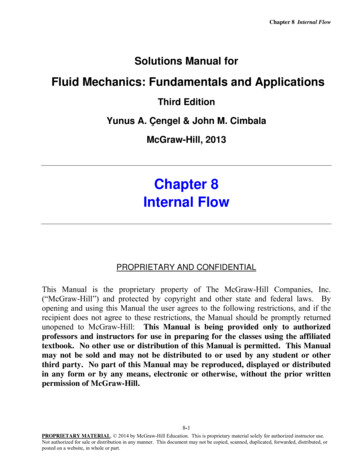
Chapter 8 Internal Flow8-11CSolutionWe are to discuss the effect of surface roughness on pressure drop in pipe flow.AnalysisIn turbulent flow, tubes with rough surfaces have much higher friction factors than the tubes with smoothsurfaces, and thus surface roughness leads to a much larger pressure drop in turbulent pipe flow. In the case oflaminar flow, the effect of surface roughness on the friction factor and pressure drop is negligible.DiscussionThe effect of roughness on pressure drop is significant for turbulent flow, as seen in the Moody chart.8-12ESolutionWe are to estimate the Reynolds number for flow through apipe, and determine if it is laminar or turbulent.Assumptions 1 The water is at 20oC. 2 The discharge area is perfectlyround (we ignore the rim effects – there appear to be some protrusionsaround the rim – three of them are visible in the picture).PropertiesThe density and viscosity of the water are 62.30 lbm/ft3,and 6.733 10-4 lbm/ft s, respectively.AnalysisWe use the people to estimate the diameter of the pipe.Assuming the guy in the blue shirt (who by the way is Secretary of theInterior Dirk Kempthorne) is six feet tall, the pipe diameter is about 13.8 ft.The average velocity is obtained from the given volume flow rate,Vavg V 4V A D2and the Reynolds number is estimated asRe D D 4V 4 V Vavg D 2 D 4 62.30 lbm/ft 3 300, 000 gal/s 231 in 3 6.733 10 4 lbm/ft s 13.8 ft 1 gal 3 1 ft 88 3.424 10 3.4 1012in where we give our final result to two significant digits. Since Re 2300, this flow is definitely turbulent.DiscussionThere is absolutely no doubt that this flow is turbulent! You can even see the unsteady turbulentfluctuations in the photograph.8-5PROPRIETARY MATERIAL. 2014 by McGraw-Hill Education. This is proprietary material solely for authorized instructor use.Not authorized for sale or distribution in any manner. This document may not be copied, scanned, duplicated, forwarded, distributed, orposted on a website, in whole or part.
Chapter 8 Internal FlowFully Developed Flow in Pipes8-13CSolutionWe are to examine a claim about volume flow rate in laminar pipe flow.AnalysisYes, the volume flow rate in a circular pipe with laminar flow can be determined by measuring the velocityat the centerline in the fully developed region, multiplying it by the cross-sectional area, and dividing the result by 2. Thisworks for fully developed laminar pipe flow in round pipes since V Vavg Ac (V max / 2) Ac .DiscussionThis is not true for turbulent flow, so one must be careful that the flow is laminar before trusting thismeasurement. It is also not true if the pipe is not round, even if the flow is fully developed and laminar.8-14CSolutionWe are to examine a claim about volume flow rate in laminar pipe flow.AnalysisNo, the average velocity in a circular pipe in fully developed laminar flow cannot be determined by simplymeasuring the velocity at R/2 (midway between the wall surface and the centerline). The average velocity is Vmax/2, but thevelocity at R/2 is 3Vr2 V ( R / 2) V max 1 2 max , which is much larger than Vmax/2.4R r R / 2DiscussionThere is, of course, a radial location in the pipe at which the local velocity is equal to the average velocity.Can you find that location?8-15CSolutionWe are to discuss the value of shear stress at the center of a pipe.AnalysisThe shear stress at the center of a circular tube during fully developed laminar flow is zero since theshear stress is proportional to the velocity gradient, which is zero at the tube center.DiscussionThis result is due to the axisymmetry of the velocity profile.8-6PROPRIETARY MATERIAL. 2014 by McGraw-Hill Education. This is proprietary material solely for authorized instructor use.Not authorized for sale or distribution in any manner. This document may not be copied, scanned, duplicated, forwarded, distributed, orposted on a website, in whole or part.
Chapter 8 Internal Flow8-16CSolutionWe are to discuss whether the maximum shear stress in a turbulent pipe flow occurs at the wall.AnalysisYes, the shear stress at the surface of a tube during fully developed turbulent flow is maximum sincethe shear stress is proportional to the velocity gradient, which is maximum at the tube surface.DiscussionThis result is also true for laminar flow.8-17CSolutionWe are to discuss how the wall shear stress varies along the flow direction in a pipe.AnalysisThe wall shear stress w remains constant along the flow direction in the fully developed region in bothlaminar and turbulent flow.DiscussionHowever, in the entrance region, w starts out large, and decreases until the flow becomes fully developed.8-18CSolutionWe are to discuss the fluid property responsible for development of a velocity boundary layer.AnalysisThe fluid viscosity is responsible for the development of the velocity boundary layer.DiscussionYou can think of it this way: As the flow moves downstream, more and more of it gets slowed down nearthe wall due to friction, which is due to viscosity in the fluid.8-19CSolutionWe are to discuss the velocity profile in fully developed pipe flow.Analysisdirection.In the fully developed region of flow in a circular pipe, the velocity profile does not change in the flowDiscussionThis is, in fact, the definition of fully developed – namely, the velocity profile remains of constant shape.8-7PROPRIETARY MATERIAL. 2014 by McGraw-Hill Education. This is proprietary material solely for authorized instructor use.Not authorized for sale or distribution in any manner. This document may not be copied, scanned, duplicated, forwarded, distributed, orposted on a website, in whole or part.
Chapter 8 Internal Flow8-20CSolutionWe are to discuss the relationship between friction factor and pressure loss in pipe flow.AnalysisThe friction factor for flow in a tube is proportional to the pressure loss. Since the pressure loss alongthe flow is directly related to the power requirements of the pump to maintain flow, the friction factor is also proportionalto the power requirements to overcome friction. The applicable relations arem PLW pump andm PLW pump DiscussionThis type of pressure loss due to friction is an irreversible loss. Hence, it is always positive (positive beingdefined as a pressure drop down the pipe). A negative pressure loss would violate the second law of thermodynam
Discussion This is not true for turbulent flow, so one must be careful that the flow is laminar before trusting this measurement. It is also not true if the pipe is not round, even if the flow is fully developed and laminar. 8-14C Solution We are to examine a claim about volume flow rate in laminar pipe flow.File Size: 1MBPage Count: 151