Transcription
CABLE DESIGNERS GUIDETABLE OF CONTENTSCABLE GEOMETRYPage7-1HOW TO SPECIFY CABLEPages 7-2, 7-3BASIC INTRODUCTORY INFORMATIONPages 7-4, 7-5GLOSSARY OF ABBREVIATIONS AND TERMSPages 7-6,7-7, 7-8WIRE AWGPage7-9SYNOPSIS OF WIRE & CABLEPages 7-10, 7-11MIL-STD-681 COLOR CODINGPage7-12MINIATURE SIGNAL & CONTROL CABLES - COLOR CODINGPage7-13INSULATING MATERIALS - COMPARATIVE PROPERTIESPage7-14WIRE TABLESPage7-15,7-16, 7-17HOW TO SPECIFY WIREPage7-18HOW TO SPECIFY PAIRSPage7-19
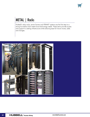
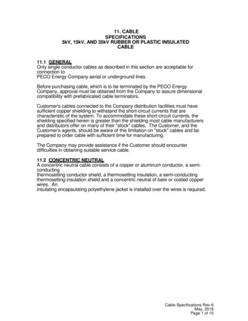
CABLE DESIGNERS GUIDECABLE GEOMETRYDesign Geometry of Multi-Conductor CablesC. Filling IntersticesTo those outside of the industry, the geometric design principles usedin cable-making may not be apparent. To assist the customer in comprehensively discussing his needs with our factory engineering staff, we offer abrief guide to the major design options and tradeoffs available. A designerscheck list for specifying cable is offered elsewhere in this section. Not all areaware that for a given number of wires, several different geometry’s maybe used to form the wires into a helical cable bundle. Any of them may bejustified, depending on cost, intended use and performance, or limitationsof the manufacturers’ equipment. National Wire & Cable Corp. has perhapsthe widest and most versatile selection of modern cable-making equipmentin the custom cable industry. We welcome your knotty design problems. Our40 years of experience in wire & cable field are at your disposal.When a cable contains a wide mixture of wire diameters, the largerwire sizes or subcables may be cable-formed so as to deliberately leaveinterstices large enough for the smaller wires to lie within tangent to twoadjacent large wires, but not in contact with the inner layer or core.D. Use of FillersWhere a layer requires more wires than are available to properly fill allpositions in that layer, round fillers are used to occupy the otherwise vacantsites. Their use ensures a round shape and provides adequate support forthe outer layers of the construction. These may be spare wires, or of plasticrod, jute, or twisted yarns or tapes. They are often used as a core member,and may be deliberately designed into a layer to permit circumferential compression in a layer during flexing of the cable.Conductor Layup Geometry OptionsCable FlexibilityA. Layer Upon layerWhen a helically cabled bundle is flexed, each of the wires in a layertend to slide along their helical path slightly with respect to the wires adjacent. If the wires are in firm contact around the entire layer, the frictionbetween them inhibits the desired sliding action, and additional stiffness isimparted to the cable. Interlayer friction can also contribute to cable stiffness. In general, any stored radial forces which contribute to the frictionshould be avoided by proper design and manufacturing techniques. Theseforces may be from unduly snug jackets, braids, wraps, or serves.When all conductors have equal diameters they can be cabled insimple layers around a suitable core or central wire. Theoretically, everylayer will contain 6 more wires than the preceding inner layer. This can beshown with a few round disks or coins. In practice this is not always true.Tolerances of insulation diameters enter the picture. Further, the conductors spiral in a helical path when formed into cable, and thus occupy anelliptically-shaped area around the circumference of the core. Typically, theeccentricity of the ellipse is about 5%. Thus about 19 conductors may fit,where 20 should if they were assumed to occupy a circular cross-section.Cable Flexibility Design AssistanceB. SubcabelingDue to the many variable factors which influence cable designs, westrongly recommend that the customer consult with our technical staff toensure proper choice of dimensions and tolerances when he generates hisown specification.For design reference, a few of the common geometry’s for subcabledand intersticed constructions are shown. The diameter of the large members is taken to be one unit of diameter. The size of the other members areshown as some decimal which relates their size to that of the large member.For layer-on-layer constructions, the table shows the factor by which thewire diameter can be multiplied to obtain the cabled bundle diameter.For some constructions small groups of wires are helically cabled intosubcables, which are then helically cabled to form the finished bundle. Theymay take these forms due to the end use requirements, (i.e.: where thedesign calls for twisted pairs, trios, etc.) or may do so mainly for the convenience of the lay-up of the required number of wires in an available site within the cable cross-section. Advantages of this method are improved flexibility of the cable, possible convenience in the intended end-use for the cableand the wide selection of geometry’s it offers the designer. Disadvantagescompared to the layer-on layer method are usually increased diameter andcost. Where there are hundreds of conductors in a cable, this method isoften used to permit cabling on relatively small cabling machines.POSSIBLE CABLE CONFIGURATIONS & RELATIVE IO1.1.1.1.2.71.QUINT1.3.01.6 AROUND 1DIAMETER OF HELICALLY CABLED BUNDLES*TO FIND THE CABLED DIAMETER OF A LAYER-ON-LAYER CONSTRUCTION, MULTIPLY THE DIAMETER OF A WIRE BY THE FACTOR SHOWN.*** All conductors are the same diameter** (these factors are typical for standardhelical cabling prectices; slight variationsmay occur on certain combinations)7-1No. 2.73.03.74.04.1No. 3DiameterFactor4.44.75.05.35.76.06.16.46.7Number NAL WIRE & CABLE custom cable manufacturing & molding www.nationalwire.comNumber 12.0Order Desk 323-225-5611
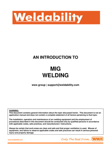
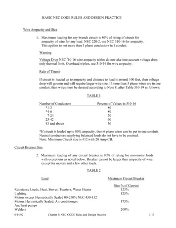
CABLE DESIGNERS GUIDEHOW TO SPECIFY CABLECustom Cable Design GuideIf you plan to specify a special cable, we highly recommend a call to our “user Friendly” technical staffwho can help speed you over the bumps.a bbacacde, fg, h, i, jkIn the absence of your own cable specification, the following checklist will assist you to completely specifythe cable you want:A.B.C.D.E.F.G.H.I.J.K.Number and gauge of conductors.Specification type of wire (military or commercial).Coding of conductors or subcables, striping or numbering, if any.Tape barrier, used as first mechanical protective layer. Can be of Vinyl, Mylar, Tedlar, Polyethylene, orpaper-fiberglass laminates.Type of electrical shielding or mechanical armor.% coverage required for electrical shieldingType of outer jacket material.Color of outer jacket, sheath markings.Wall thickness of outer jacket.Necessary physical or environmental requirements, see below.Minimum and maximum overall diameter.Physical Requirements1. Length, tolerance; Diameter, tolerance.2. Overall tensile strength, if applicable.3. Weight limitations.4. Minimum bend radius.Environmental Requirements1. Minimum and maximum operating temperatures.2. Physical abuse: terrain, degree of movement of flexing, possible sudden impacts or pressures, etc.3. Surrounding medium: water, oil, sunlight, ice, fuels, air, etc.Electrical Requirements1. Voltage rating of the conductor insulation.2. Maximum current expected in the conductors.3. Amount of electrical or magnetic shielding required.4. Capacitance requirements.NATIONAL WIRE & CABLE custom cable manufacturing & molding www.nationalwire.comOrder Desk 323-225-56117-2
CABLE DESIGNERS GUIDEHOW TO SPECIFY CABLEInsulated ConductorsSpecify quantity, gauge, stranding and insulation type for the conductors. Allowance of 10% spares is a common practice.Preferably suggest an agency specification for the wires. (i.e.: UL,CSA, MIL and their proper type or style no.)You may need a MIL reference to preferred wire types and jacket materials in various applications and environments.FillersFillers are used in lieu of a wire to fill space in a cable bundle so thatit can retain its controlled shape and geometry. Their use promotes roundness and uniform flexibility.Preferable fillers are plastic rods, tapes, or fibers, having physicalproperties similar to those of the wire insulation. Round glass-fiber braidcan be used for high temperature applications. Fibrillated polypropylene iscommonly used; cotton or jute is used less frequently.Cables (within the main cable)Individually cabled groups of wires within the cable may be referred toas sub-cables.The constructional details of sub-cables should be just as complete asthe main cable in which they are used. (i.e.: wire details, cabling, coding,shields, jacketing.)Sub-cabling permits neat and simple formation of branch legs from themain cable and can be used to aid in identifying wire groups.Subcables may be individually jacketed. Jackets may be solid colors,or may be color-striped over solid colors.CablingThe purpose of helical twist used in cabling the wires into a roundbundle is twofold. It holds the wires in a unit, and it will act to neutralizethe tension and compression forces which occur in the wires each time thecable is bent or flexed. Since most cables use stranded wires the cableforming must be done without untwisting the strands of the individual insulated stranded wires. This requires very special machinery, not just a drillmotor.Suggested wording: “Cabling shall be done on a tubular or planetarytype helical cabling machine in such a fashion that no residual twist is introduced into the individual cable members.”The axial distance per turn is called the lay length. The lay lengthshould be between 8 to 16 times the pitch diameter of that layer of wires.(Pitch diameter is measured from center-to-center of diametrically opposedwires in a given layer.)Although the rotation direction may be the same for all layers of wiresopposite directions of rotation for each layer in a cable is usually preferredand is called contra-helical construction.Overall RFI Shielding (Over the cabled bundle of wires)1.Metal-Foil Faced tape RFI shieldsThe lowest-cost, lightest and least effective shield method. Can beapplied single or double-sided, in single or multiple layers. Usually appliedin contact with an uninsulated “drain” wire used for connection of shield.Usually made with aluminum or copper metal foil glued to a thermoplastic polyester (Mylar) backing, the most common thickness’ of material are0.00035” of metal foil and 0.0005” of backing tape, plus perhaps 0.00015” ofglue for finished thickness of 0.001 “ . NWC normally uses a heavier backing (0.001”) for a total thickness of 0.0015” to avoid shielding degradation.Shield performance will degrade if cable handling causes tape to deform,or stretch so that metal begins to flake or crack. Cable flexibility is reducedslightly when a foil shield is added.7-32.Braided RFI shieldsThe most common and perhaps the most durable cable shield is abraided tubular shield made of small copper wires. Wire sizes range from#38 to #32 AWG. A braid is the standard coaxial cable outer conductor. Itmay be applied in one or more layers. In conjunction with metallic tapeor foils, performance becomes very good. Braiding is a continuous operation, any desired length can be made. A braid is machine-formed directlyonto the cable as contra-helical interlocking spirals of groups of fine wires.The effectiveness of the shield braid depends on how well it covers upthe surface of the cable. A minimum coverage requirement of 90% of thecable surface is common. Machinery limitations make coverage in excessof 96% impractical for a single-layer braid. For braids that must “push-back”or swell easily, the braid angle should be specified. We recommend anglesbetween 20 and 38 degrees for that service. Various methods of shieldingcan be combined for optimum RFI protection. See “Shielding Effectiveness”elsewhere in this section.Outer Jacket/SheathThe choice of outer cable covering material is usually a compromisebetween cost, agency recognition/ratings, flexibility and durability.A chart of relative properties is shown in Table A.A thin-wall jacket is usually most flexible; however it can be prone towrinkle at tight bends, and often shows more “wireform” of the underlyingcable surface.For plastic jacketed cables, typical wall thickness is 10% of the unjacketed diameter or 0.010” minimum. Cable jacket walls below 0.010” are notrecommended. Maximum walls rarely need to exceed 0.125” in plastics, or0.250” in rubbers.Some agencies (UL, CSA) have their own preferred wall sizes whichmust be met to obtain their sanction for their stated use.TypeFlexibilityAbrasionWeatheringTemp FBurialVinylsBetterBetterGood-40 221GoodNeopreneBestBestBetter- 65 180BetterPolyethylenesGoodGoodBest-65 160BestPolyurethaneBetterBestBetter-65 160BetterTPRBestGoodGood-65 125n/aColorsCable sheath plastic compounds can be pigmented nearly any color,and are often color-matched to customer requirements. However, nearly allmaterials will discolor in sunlight or ultraviolet. Use of carbon-black pigmentis very common as it readily makes the jackets opaque to UV and sunlight.Best to supply your own color sample for matching if not using black. Colorsamples preferably should be of the same material as the jacket compound.Specify if color must be correct for both fluorescent and daylight.Jacket MarkingsAlmost any legend of your choice can be indented or ink marked continuously onto the jacket.Agency SpecificationsContact us for a list of wire & cable specifications from various agencies.Details of cabling design are available elsewhere in this section under“Designer’s Guide on Cable Geometry.”NATIONAL WIRE & CABLE custom cable manufacturing & molding www.nationalwire.comOrder Desk 323-225-5611
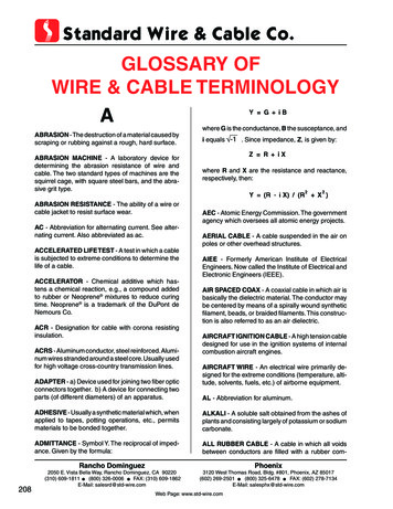
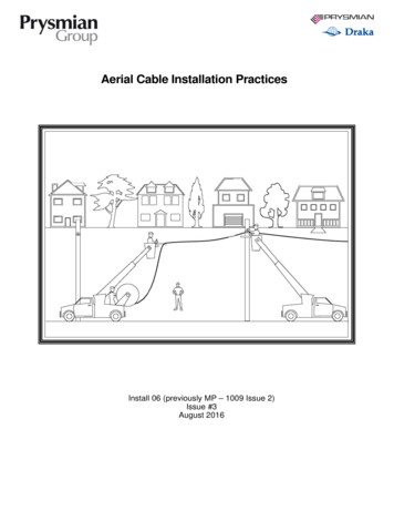
CABLE DESIGNERS GUIDEBASIC INTRODUCTORY INFOElectrical CapacitanceElectrical capacitance exists between each conductive surface in acable and all other conductive surfaces in and around the cable An understanding of the relative amount of capacitance to be expected in a cable ishelpful in specifying cable and designing terminal equipment for the cable tobe used. Although capacitance in a cable may have negligible effect on DCor 60 cycle AC cable circuits used for power or control, it does affect higherfrequency AC voltages.Charge on Conductive SurfacesElementary electron theory states that the electron is the basic unitof negative electric charge; that a large charge is simply a large collectionof electrons. The more electrons that are concentrated on a surface, thelarger the electric charge on that surface. Positively charged surfaces maybe regarded as having a deficiency of electrons. Charge is measured incoulombs. One coulomb consists of many trillions of electrons. Since theyrepel each other, a collection of electrons will distribute over a surface.CurrentWe can force an exchange of charge (electrons) between two conductive surfaces if we connect any source of voltage, such as a battery, betweenthem. Since electrons in motion constitute an electric current, flows off onesurface through the battery onto the other, until the repulsion of charges being forced onto the surfaces equals the forcing voltage. When the battery isremoved, a voltage equal to that of the battery exists between the surfacesdue to the stored charge. If the voltage source is AC, the charge exchangeoccurs each half cycle. The voltage source thus must handle this chargingcurrent in addition to any other current which may pass through circuitryconnected to the two surfaces.CapacitanceThis behavior of charge on surfaces is termed capacitance. Capacitance may be defined as the ratio of voltage between two surfaces, dividedby their difference in charge; and is measured in units called farads. Capacitors, or condensers, are sets of surfaces deliberately arranged to controlthe capacitance between them. Shielded wires and cables also have capacitance between the conductors and shields which should be consideredin their design and application. Commonly used values of capacitance aremicrofarads (mfd) or (10-6 fd) and picofarads (pf) or (10-12 fd).DielectricsThe spacing or insulating material between two surfaces of a capacitor is called a dielectric. It may be vacuum, air, or one of many insulatingmaterials. With the exception of gases, all insulating materials increase thecapacitance between the surfaces. The term dielectric constant is used toshow how large this effect is for various materials. If the space between twosurfaces is filled with a material having a dielectric constant of 2, then thecapacitance between the surfaces will be 2 times greater than it would befor an air or vacuum dielectric.c40.d DCoaxial Conductor FIG 1.5.40.Shielded Pairs FIG 2.Coaxial Wires (Fig 1)The capacitance per foot between a single insulated wire and a shieldaround it is:(7.36) x (e)C ––––––––––– mmfd per footLg10 (D/d).where e is the dielectric constant of the insulation between wire andshield; and D/d is the diameter ratio of shield ID to conductor OD. The onlyway in which the capacitance can be selected is by choice of insulation having a low dielectric constant, or by choosing a suitable value of D/d.Shielded Pairs (Fig 2)Shielded pairs have three capacitance’s involved which combine toproduce the effective wire to wire capacitance. Fig. 2 illustrates these capacities. Since the wire-to-shield capacitance’s of each conductor are essentially in series, the effect of the two 40, mmfd capacitance’s is to producean apparent 20 mmfd between the two wires in addition to the 5. mmfdwhich will exist whether the shield is present or not. Thus the effective capacitance is 20. 5. 25. mmfd./ft from wire to wire.(Ref. to Mil-C-17.)Multi-Conductor Cable BundlesThe capacitance from a wire to all else in a large cable bundle of identical wires may vary widely depending on insulation and geometry. In general, however, it will have values ranging from 40. to 65. mmfd/ft for PVCinsulation (where C 4.), and will vary from this for other materials. Conductors in the outer layer of a cable bundle which is overall-shielded will tendto have a higher capacitance than those closer to the bundle center. Typicalvariation for PVC’ insulated wires will be a 15-20% rise in capacitance forconductors in the layer closest to the overall shield.Wire InsulationNot all dielectrics are suitable for use on wire and cable. The morecommonly used insulation’s are listed in Table A. Most wire insulation choices are based on a compromise among cost, electrical performance, and thephysical and chemical properties required for the application. With the exception of Polytetrafluoroethylene (PTFE) and some polyolefins, most wireinsulation’s exhibit appreciable increases in their dielectric constant and insulation leakage with increasing temperature or frequency. This may makethem undesirable for use where the capacitance, characteristic impedanceor the leakage must be constant, such as in coaxial cable or instrumentationcables.GeometryThe shape, diameter and spacing of the conductors and shields determine the capacity between them. Coaxial cables are a special applicationversion of a single shielded conductor and may be treated in the sameway.NATIONAL WIRE & CABLE custom cable manufacturing & molding www.nationalwire.comOrder Desk 323-225-56117-4
CABLE DESIGNERS GUIDEBASIC INTRODUCTORY INFOInductanceWhen current flows in a wire it creates a magnetic field about thewire, which generates voltages along the same wire as the current changes. These opposing voltages act to limit the rate at which the current canchange. This effect is termed inductance and is measured in units calledhenrys. The self inductance of a round straight copper wire is on the orderof .4 micro-henry/ft, and is relatively unaffected by diameter or length ofwire. The self inductance of twisted pairs of wires is on the order of .08micro-henry/ft; while the mutual inductance of a coaxial construction is .14Lg10(D/d) micro-henrys/ft.Signal Delay in CablesThe velocity of a wave in a coax is usually expressed as a percentageof the velocity of light. For instance, a polyethylene insulation gives a “propagation velocity” of 65.9% of light velocity. This is sometimes expressed asa velocity factor of .659.Characteristic ImpedanceA transmission line such as a coaxial cable or shielded pair can beconsidered as a wave-guiding device in the broad sense. The relative amplitudes of the electric and magnetic fields due to a signal within the cableare determined by the capacitance and inductance per unit length of cable(assuming no reflections from the load.)The characteristic impedance (Z) is the ratio of the two fields, orMechanical DelayThe electronic systems designer should consider possible problemswhich may arise due to cable delay. For instance, in a multi-conductor cableof coax, the coax in the center of the bundle will be shorter than those in theouter layers by 4% to 6%, which mechanically can introduce delay in thesignals traveling the long path.Dielectric DelayAlthough radio waves travel at the speed of light in free space or inair, this speed is much less when the wave is guided through coax or othershielded cables, where the electric field is contained in an insulator otherthan air.Suppose that a radio-frequency sine-wave signal generator is connected to both an antenna and a 1000 foot length of coaxial cable, so thatits signals will be launched simultaneously into both, and we go to the farend of the cable to see which arrives first.When the generator is keyed on, the signal from the antenna arrivesfirst, traveling at the speed of light in air, taking about one microsecond tomake the trip.Shortly thereafter, the same identical signal will arrive at the end of thecoax cable, having taken longer to travel the same distance. It did not travelas fast, so its arrival at the end of the cable was “delayed” compared to thearrival of signal from the antenna.TABLE AAir--****Nom afluoroethylene(PTFE) (TFE & EEP)2.070.0%1.45Polypropylene2.169.0%1.47Foam .0%2.03Nylon (#610)3.0**57.8%1.76Neoprene5.0***44.6%2.28Rubber (Buna S)2.9***58.7%1.73Rubber (Butyl)2.35***65.3%1.56Silicone Rubber (SE972)3.16***56.3%1.80Z E/H L/Cwhere C and L are farads and henrysAnother equation for finding the value of Z is:101600Z ––––––––––(C) (% V.P.)where C is in pf/ft and V.P. is the propagation velocity expressed in percent.The resistance of the conductors and shield attenuates the signal in atransmission line, but at radio frequencies has little effect in determining thecharacteristic impedance.Pulse CablesCables designed for transmission of pulses for digital signals havecarefully controlled surge impedances and capaticance. Generally they are93 to 120 ohm constructions. A series of these for general use are shown inthe instrument cable section.Reference BooksRadio Engineers Handbook; Terman; McGraw-HillPulse, Digital, & Switching Waveforms; Millman & Taub; McGraw-HillReference Data For Radio Engineers; I. T. & T. Corp.; Stratford PressAdditional InformationNational Wire & Cable Corp. invites our inquiry about special-purposeshielded cable, whether coaxial or multi-conductor.National is prepared to discuss your particular needs, provide designinformation and fabricate cable to meet your specifications.* One microsecond is one millionth of a second** Susceptible to changes due to humidity. Absorbes moisture***Dielectric constant varies widely with frequency. Many different values of dielectricconstant may be obtained since the materials are a blend of filler and plasticizers withthe base material, all of which have differing values of e.****varies depending on the method used to support the center conductor of the cable.Inductance of shield and conductor linit upper value to about 96%.7-5NATIONAL WIRE & CABLE custom cable manufacturing & molding www.nationalwire.comOrder Desk 323-225-5611
CABLE DESIGNERS GUIDEGLOSSARY Abbreviations & TermsAccelerator - A chemical additive which hastens thechemical reaction under given conditions, known also asa promoter.Acceptance Test – A test made to demonstrate the degree of compliance with specified requirements.Adhesive - A material capable of holding other materialstogether by surface attachment.Aging – The change in properties of a material with timeunder given conditions.Ambient Temperature – The temperature of a surrounding cooling medium, such as gas or liquid, which comesinto contact with heated parts of an apparatus.Angle of Advance - The angle between a line perpendicular to the axis of the cable and the axis of any onemember or strand of the braid.Annealed Wire – Wire which has been softened by heating. Sometimes referred to as soft drawn wire.Armored Cable – A cable covered with a heavy outerbraid of metal or spiral steel tapes for the purpose of mechanical protection.Attenuation – The power drop or signal loss in a circuit,expressed in decibels, db.AWG – American Wire Gauge. The standard for copperwire sizes. The diameters of successive sizes vary ingeometrical progression.B and S Gauge – Brown and Sharpe wire gauge wherethe conductor sizes ruse n geometrical progression. Adopted as the American Wire Gauge standard.B.C. – Abbreviation for bare copper.Blown Jacket – The common term given to an outercovering of insulation of a cable, that was applied by thecontrolled inflation of the cured jacket tube and the pullingof the cable through it.Bond Strength – The amount of adhesion betweenbonded surfaces.Braid – A woven protective outer covering over a conductor or cable. It may be composed of any filamentary materials such as cotton, glass, nylon, tinned copper, silver,or asbestos fibers.Braid Angle – The angle between the axis of the cableand axis of any one member or strand of the braid. (Alsoknown as Angle of Advance).Breakdown (Puncture) – A disruptive discharge throughinsulation.Cavity – Depression in a mold.Chromel-Alumel – Two alloys used in forming one typeof thermocouple pair. Chromel is primarily an alloy ofchrome and nickel, and Alumel an alloy of Aluminum,nickel, manganese, and silicone.Circular Mil – A circular mil is a unit of area equal to Pi4 of 78.54 percent of a square mil. The cross-sectionalarea of a circle in circular mils is, therefore, equal to thesquare of its diameter in mils. A circular inch is equal to1,000,00 circular mils.Coax – Abbreviation for coaxial cable. A single solid orstranded conductor over which is extruded a dielectricmaterial. An over-all RF Shield of wire braid. Mylarbacked foil, or metal tubing is added over the inner dielectric materials with an outer sheath of dielectric materialextruded over the shield to form a protective covering.Cold Bend – Normally used with reference to a test.Cold Bend Test, which is a procedure whereby a sampleof wire or cable is attached to a mandrel within a coldchamber, and when a specified temperature is reached,the wire or cable is wound around the mandrel a givennumber of turns at a given rate of speed. The sample isthen removed and examined for defects or deteriorations.In the materials construction.Cold Flow – See Creep.Cold Molding – Shaping at room temperature and curingby subsequent baking.Color Coding – Color coding is the application of a colored jacketing material on the conduction wire. Also colorcoding may be accomplished by the application of helically striped color on the outer surface of a jacketed wire.Color Shades – These are the basic 12 colors as specified in MIL-STD-104, within certain limits of light and darkas shown on the color chips accompanying the standardspecification. In the case of synthetic or rubber insulation, Polychloroprene (Neoprene) nylon or compoundfilled tapes for circuit identification, somewhat wider limitswill be permitted in color shades provided all colors in thecable are easily distinguishable from each over.Compression Molding – A method of molding thermosets. Compound (usually preheated) is placed in an openmold, is closed, and heat and pressure applied until material is cured. This process can also be used with synthetic rubber materials.Compressive Strength – Crushing load at failure dividedby the original sectional area of the specimen.Concentric Lay – A concentric lay conductor or cable iscomposed of a central core surrounded by one or more layers of helically wound strands or insulated conductors.Breakout – A breakout is the common name given to theexit point of a conductor or number of conductors from acable of which they are a part. This point is usually harnessed or sealed with some synthetic rubber compound.Concentric Stranding – Stranding in which the individual filaments are spiraled in layers around a central core.As a general rule, each layer after the first has six morestrands than the preceding layer and is applied in a direction contrahelical of the layer under it.Buna Rubber – A synthetic rubber made by polymerization of butadiene. Buna-N is a copolymer of butadieneand acrylonitrile (C3 H3 N3). Buna-S is a copolymer ofbutadiene and styrene.Condensation – A chemical reaction in which two ormore molecules combine resulting in a molecule of greater density. For example, water vapor condenses to formwater.Bunched Lay – In a bunched lay conductor or cable, thestranded members are twisted together in the same direction without regard to geometrical arrangement.Conductor – A conductor is a slender rod or filament ofdrawn metal of circular cross section or group of suchrods or filaments not insulated from one another, suitablefor transmitting current.Capacitance (Capacity) - that property of a system ofconductors and dielectrics which permits the storage ofelectricity when potential differences exist betwee
design calls for twisted pairs, trios, etc.) or may do so mainly for the conve-nience of the lay-up of the required number of wires in an available site with-in the cable cross-section. Advantages of this method are improved flexibil-ity of the