Transcription
Catalyst 3650 Switch Getting Started Guide About This Guide, page 1 Shipping Box Contents, page 2 Running Express Setup, page 3 Managing the Switch, page 7 Installing the Switch, page 10 Securing the AC Power Cord (Optional), page 14 Connecting the StackWise Cables, page 14 StackWise Cabling Configurations, page 17 Connecting to the Switch Ports, page 17 Troubleshooting, page 19 Obtaining Documentation and Submitting a Service Request, page 20 Related Documentation, page 21About This GuideThis guide describes how to use Express Setup to initially configure your Catalyst 3650 switch. Theguide also covers switch management options, installation, basic rack-mounting, stacking, port andmodule connections, and troubleshooting.NoteThe illustrations of the Catalyst 3650 switch are not intended to depict any particular color scheme. Theyare provided as a reference for various features and markings described within this guide.For more installation and configuration information, see the Catalyst 3650 documentation on Cisco.com.For system requirements, important notes, limitations, open and resolved bugs, and documentationupdates, see the Catalyst 3650 release notes on Cisco.com.When using the online publications, refer to the documents that match the Cisco IOS software versionrunning on the switch.Cisco Systems, Inc.www.cisco.com
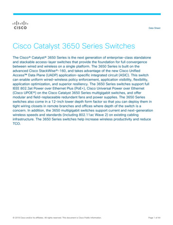
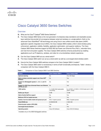
Shipping Box ContentsFor translations of the warnings that appear in this publication, see the Regulatory Compliance andSafety Information for the Catalyst 3650 Switch on Cisco.com.Shipping Box ContentsThe shipping box contains the model of the switch you ordered and other components needed forinstallation, as shown in Figure 1. Some components are optional, depending on your order.Verify that you have received these items. If any item is missing or damaged, contact your Ciscorepresentative or reseller for instructions.NoteFigure 1Components Delivered in the Shipping BoxDan ocu Prodd C me ucom nta tplia tionnceACTV201XCatalyst 3650 48PoE 12X 13X2X10G24X 25X36X 37X48XG1G2G3TE3 G43TE417108514131211961539017641Catalyst 36501 switch2 (power suppliesand fan modules not shown)392(Optional) AC power cord210 Cable guide3Product documentation and compliancedocument11 M4.0 x 20mm Phillips pan-head screw4Four rubber mounting feet12 (Optional) RJ-45 console cable25Ground lug screw and ring terminal13 (Optional) USB console cable26Two 19-inch mounting brackets14 (Optional) StackWise (Stackwise-160) cable to connect a Catalyst 3650switch to another Catalyst 3650 switch (0.5-meter, 1-meter, or 3-meter)27Four number-12 pan-head screws15 (Optional) Two StackWise (Stackwise-160) adapters28Four number-10 pan-head screwsEight number-8 Phillips flat-head screwsCatalyst 3650 Switch Getting Started Guide2OL-29733-01
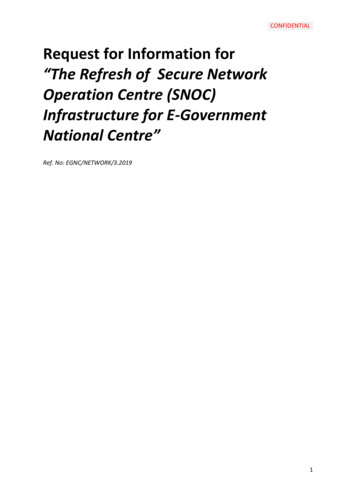
Running Express Setup1. Catalyst 3650-48PS-L switch is shown. Your switch model might look different.2. Item is orderable.3. Fan modules are installed in the switch. Power supply modules are not installed in the switch.Running Express SetupUse Express Setup to enter the initial IP information. This action enables the switch to connect to localrouters and the Internet. You can access the switch through the IP address for further configuration.NoteTo use the CLI-based initial setup program, see Appendix C, “Configuring the Switch with theCLI-Based Setup Program,” in the Catalyst 3650 Switch Hardware Installation Guide.You need this equipment:Note PC or laptop with Windows Vista, XP, or 7 Browser (Internet Explorer 5.5, 6.0, or 7.0, or Firefox 1.5, 2.0, or 3.0) with JavaScript enabled Straight-through or crossover Category 5 Ethernet cableBefore running Express Setup, disable any pop-up blockers or proxy settings in your browser and anywireless client running on your PC or laptop.To run Express Setup:Make sure that nothing is connected to the switch.347774Step 1ACTV01XCatalyst 3650 4812X 13XPoE 2X10G24X 25X36X 37X48XStep 2TE3 G4TE4During Express Setup, the switch acts as a DHCP server. If your PC or laptop has a static IP address, temporarilychange your PC or laptop settings before you use DHCP.NoteStep 3G3Write down the static IP address. You will need this IP address in Step 14.Install the power supply modules. See the “Power Supply Installation” chapter in the Catalyst 3650 Switch HardwareInstallation Guide for instructions.http://www.cisco.com/go/cat3650 hwNoteFor information on 250-W AC power supply support on the PoE-capable switch models, refer to the ReleaseNotes for the Cisco Catalyst 3650 Switch on Cisco.com.Catalyst 3650 Switch Getting Started GuideOL-29733-013
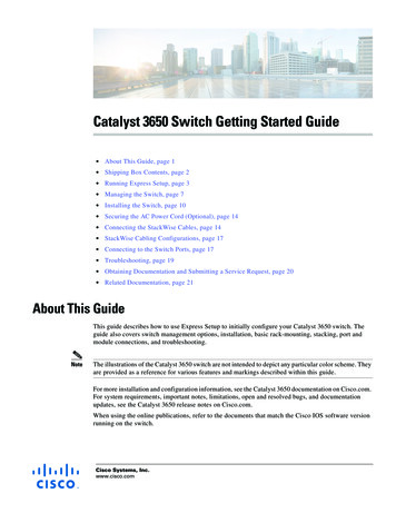
Running Express SetupStep 4Power the switch.DC power switches: See the wiring instructions in theCatalyst 3650 Switch Hardware Installation Guide onCisco.com:347767AC power switches: Plug the AC power cord into theswitch power supply and into a grounded AC /www.cisco.com/go/cat3650 hwStep 5Observe the POST results. Approximately 30 seconds after the switch powers on, it begins the power-on self-test(POST), which can take up to 5 minutes to complete.During POST, the SYSTEM LED blinks green. When POST is complete, the SYSTEM LED turns solid green. TheACTV LED is green if the switch is acting as the active switch.NoteBefore going to the next step, wait until POST is complete.Troubleshooting:If the SYST LED does not turn solid green, or turns amber, the switch failed the POST. Contact your Ciscorepresentative or reseller.Step 6Press and hold the Mode button until all the LEDs next tothe Mode button turn green.You might need to hold the button for more than 3seconds.ACTV01XCatalyst 3650 4812X 13XACTVPoE 2X10G24X 25X36X 37X48XTroubleshooting:G3TE3 G4TE4347817The switch is now in Express Setup mode.If the LEDs next to the Mode button blink when you pressthe button, release it. Blinking LEDs mean that the switchis already configured and cannot go into Express Setupmode. For more information, see the “Resetting theSwitch” section on page 20.Catalyst 3650 Switch Getting Started Guide4OL-29733-01
Running Express SetupConnect a Category 5 Ethernet cable to a port: Any 10/100/1000 or 10/100/1000 PoE Ethernetports on the switch front panel. The RJ-45 management port on the switch rear panel.347820Step 7ACTV01XConnect the other end of the cable to the Ethernet port onyour PC or laptop.Catalyst 3650 4812X 13XPoE 2X10G24X 25X36X 37X48XG3TE3 G4TE4Wait until the port LEDs on the switch and your PC orlaptop are green or blinking green. Green LEDs indicatea successful connection.Troubleshooting:If the port LEDs do not turn green after about 30 seconds,make sure that:Step 8 You connected the Ethernet cable to one of thedownlink switch ports (not to the console port). You are using an undamaged Category 5 or 6Ethernet cable. The other device is turned on.Start a browser session on the PC or laptop, and enter the IP address https://10.0.0.1. When prompted, enter thedefault password, cisco.NoteThe switch ignores text in the username field.The Express Setup window appears.Troubleshooting:If the Express Setup window does not appear, make sure that any browser pop-up blockers or proxy settings aredisabled and that any wireless client is disabled on your PC or laptop.Catalyst 3650 Switch Getting Started GuideOL-29733-015
Running Express SetupStep 9Enter this information in the Network Settings fields:NoteAll entries must be in English letters.In the Management Interface (VLAN ID) field, the default is 1. NoteWe recommend that you use the default VLAN value. During Express Setup, VLAN 1 is the only VLAN onthe switch. Enter a new VLAN ID only if you want to change the management interface through which youmanage the switch. The VLAN ID range is 1 to 1001. In the IP Address field, enter the switch IP address. In the Subnet Mask field, click the drop-down arrow, and select a subnet mask. In the Default Gateway field, enter the IP address for the default gateway (router). Enter your password in the Switch Password field. The password can be from 2 to 25 alphanumeric characters,can start with a number, is case sensitive, allows embedded spaces, but does not allow spaces at the beginningor end. In the Confirm Switch Password field, enter your password again.NoteYou must change the default password, cisco.(Optional) Enter this information in the Ethernet Management Port Settings fields:In the IP Address field, enter the IP address of the Ethernet management port. In the Subnet Mask field, clickthe drop-down arrow, and select an IP Subnet Mask. Step 10(Optional) You can enter other administrative settings in the Optional Settings fields. You can enter the OptionalSettings information now or enter it later using the Device Manager interface. For example, the optionaladministrative settings identify and synchronize the switch for enhanced management. NTP automaticallysynchronizes the switch clock with the network clock. You can manually set the system clock if the switch shouldhave different settings.Step 11(Optional) You can select the Advanced Settings tab on the Express Setup window and enter the advanced settingsnow or enter them later using the Device Manager interface. In the Telnet Access field, click Enable if you are going to use Telnet to manage the switch by using thecommand-line interface (CLI). If you enable Telnet access, you must enter a Telnet password. In the Telnet Password field, enter a password. The Telnet password can be from 1 to 25 alphanumericcharacters, is case sensitive, allows embedded spaces, but does not allow spaces at the beginning or end. In theConfirm Telnet Password field, reenter the Telnet password. In the SNMP field, click Enable to enable Simple Network Management Protocol (SNMP). Enable SNMP onlyif you plan to manage switches by using Cisco Network Assistant or another SNMP-based network-managementsystem. If you enable SNMP, you must enter a community string in the SNMP Read Community field, the SNMP WriteCommunity field, or both. SNMP community strings authenticate access to MIB objects. Embedded spaces arenot allowed in SNMP community strings. When you set the SNMP read community, you can access SNMPinformation, but you cannot change it. When you set the SNMP write community, you can both access andchange SNMP information. In the System Contact and System Location fields, enter a contact name and the wiring closet, floor, or buildingwhere the switch is located. (Optional) In the Enable IPv6 field, click Enable to enable IPv6 on the switch. The IPv6 field is enabled bydefault.NoteEnabling IPv6 restarts the switch when you complete Express Setup.Catalyst 3650 Switch Getting Started Guide6OL-29733-01
Managing the SwitchStep 12Click Submit to save your changes and to complete the initial setup.After you click Submit: The switch is configured and exits Express Setup mode. The browser displays a warning message and tries to connect with the earlier switch IP address. Typically,connectivity between the PC or laptop and the switch is lost because the configured switch IP address is in adifferent subnet from the IP address on the PC or laptop.For more information about Express Setup fields, see the online help for the Express Setup window.Step 13Disconnect the switch from the PC and laptop, and install the switch in your network. See the “Installing the Switch”section on page 10.Step 14If you changed the static IP address on your PC or laptop in Step 2, change it to the previously configured staticIP address.Step 15See the “Managing the Switch” section on page 7 for information about configuring and managing the switch.Managing the SwitchAfter completing Express Setup and installing the switch in your network, you can use these options forconfiguration: Configuration Wizard Device Manager Cisco Network Assistant Command-Line Interface Other Management OptionsConfiguration WizardThe Configuration Wizard is a Web-based controller user interface (UI) that lets you complete the initialwireless configuration after you configure the IP address, local username, and password or authorizationusing the authentication server. Using the Web UI, you can configure the controller, WLAN, and radiosfor all initial operations, establish management parameters, set security policies, access softwaremanagement commands, configure system logs, and other tasks.For more information on using the Configuration Wizard, see switch software configuration guide onCisco.comDevice ManagerThe simplest way to manage the switch is by using Device Manager in the switch memory. Use DeviceManager for basic switch configuration and monitoring. This web interface offers quick configurationand monitoring. You can access it through a web browser.To display Device Manager:Step 1Start a web browser on your PC or laptop.Catalyst 3650 Switch Getting Started GuideOL-29733-017
Managing the SwitchStep 2Enter the switch IP address, username, and password assigned in Step 9 above, and press Enter.The Device Manager page appears. Refer to the Device Manager online help for more information.Troubleshooting:If Device Manager does not appear: Confirm that the port LED for the switch port connected to your network is green. Confirm that the PC or laptop that you are using has network connectivity by connecting it to awell-known web server in your network. If there is no network connection, troubleshoot the networksettings on the PC or laptop. Make sure that the switch IP address in the browser is correct. If the switch IP address in the browser is correct, the switch interface LED is green, and the PC orlaptop has network connectivity, then continue troubleshooting by reconnecting the PC or laptop tothe switch. Configure a static IP address on the PC or laptop that is in the same subnet as the switchIP address. When the LED is green on the switch port that is connected to the PC or laptop, reenter the IPaddress of the switch in a browser to display Device Manager. When Device Manager appears,continue with the configuration.Cisco Network AssistantCisco Network Assistant is a software program that you download from Cisco.com and run on your PCor laptop. It offers advanced options for configuring and monitoring multiple devices, includingswitches, switch clusters, switch stacks, routers, and access points. Network Assistant is free—there isno charge to download, install, or use it.To use Cisco Network Assistant:Step 1Go to this Web address: tmlNoteYou must be a registered Cisco.com user, but you need no other access privileges.Step 2Click the Download Software link, and select the version you want to download.Step 3Find the Cisco Network Assistant installer.Step 4Download the Cisco Network Assistant installer, and run it. (You can run it directly from the web if yourbrowser offers this choice.)Step 5When you run the installer, follow the instructions. In the final panel, click Finish.See the Cisco Network Assistant online help and the Cisco Network Assistant Getting Started Guide formore information.Catalyst 3650 Switch Getting Started Guide8OL-29733-01
Managing the SwitchCommand-Line InterfaceYou can enter Cisco IOS commands and parameters through the CLI by using one of these options: USB Console Port RJ-45 Console Port Ethernet Management PortNoteYou cannot use the RJ-45 console port and the USB console port at the same time. The USBconsole port takes precedence over the RJ-45 port when both are connected.USB Console PortNoteIf you are connecting a Microsoft Windows-based PC or laptop to the switch USB console port, installthe USB device driver before you connect for the first time. See the Catalyst 3650 Switch HardwareInstallation Guide for instructions.Step 1Connect a USB cable to the PC or laptop USB port. Connect the other end of the cable to the mini-B(5-pin-connector) USB port on the switch front panel.Step 2Start a terminal-emulation program on the PC or laptop.Step 3Configure the PC or laptop terminal emulation software for 9600 baud, 8 data bits, no parity, 1 stop bit,and no flow control.Step 4Use the CLI to configure the switch. See the Catalyst 3650 Switch Software Configuration Guide andthe Catalyst 3650 Switch Command Reference.RJ-45 Console PortStep 1Connect the RJ-45-to-DB-9 adapter cable to the 9-pin serial port on the PC or laptop. Connect the otherend of the cable to the switch console port on the rear panel.Step 2Start a terminal-emulation program on the PC or laptop.Step 3Configure the PC or laptop terminal emulation software for 9600 baud, 8 data bits, no parity, 1 stop bit,and no flow control.Step 4Use the CLI to configure the switch. See the Catalyst 3650 Switch Software Configuration Guide andthe Catalyst 3650 Switch Command Reference.Ethernet Management PortStep 1Connect a Category 5 Ethernet cable to the Ethernet port or the PC or laptop. Connect the other end ofthe cable to the management port on the switch rear panel.Catalyst 3650 Switch Getting Started GuideOL-29733-019
Installing the SwitchStep 2Start a Telnet session on the PC or laptop.Step 3Enter the switch IP address that you assigned using Express Setup.Step 4Use the CLI to configure the switch. See the Catalyst 3650 Switch Software Configuration Guide andthe Catalyst 3650 Switch Command Reference.Other Management OptionsCisco Prime Infrastructure combines the wireless functionality of Cisco Prime Network Control System(NCS) and the wired functionality of Cisco Prime LAN Management Solution (LMS) with applicationperformance monitoring and troubleshooting capabilities of Cisco Prime Assurance Manager. For moreinformation, see the Cisco Prime Infrastructure documentation on Cisco.com.See the “Accessing Help Online” section on page 20 for supporting documentation.Installing the SwitchThis section describes basic 19-inch rack-mounting. See the Catalyst 3650 Switch Hardware InstallationGuide for other optional bracket information. The illustrations show a Catalyst 3650-48PS-L switch.You can install and connect other Catalyst 3650 switches as shown.Equipment That You Need Phillips screwdriver to rack-mount the switch. Torx T15 Allen key shipped with the stacking kit (or a Torx T15 screwdriver) to attach the StackWise(Stackwise-160) adapter.Before You BeginBefore installing the switch, verify that these guidelines are met:Note Clearance is maintained so that the LEDs on the front panel can be read. AC power cord reaches from the AC power outlet to the rear-panel connector. The switch rear panel has a clearance of 4.4 in. (11.1 cm).For information on 250-W AC power supply support on the PoE-capable switch models, refer to theRelease Notes for the Cisco Catalyst 3650 Switch on Cisco.com. When it is installed, the 1025-W power supply module extends beyond the rear of the switch. Beforeyou install the power supply module:– Make sure that the switch is rack-mounted before you install it.– Verify that there is enough clearance behind the switch for the extended power supply module.Catalyst 3650 Switch Getting Started Guide10OL-29733-01
Installing the Switch Cabling is away from sources of electrical noise, such as radios, power lines, and fluorescentlighting. Make sure the cabling is safely away from other devices that might damage the cables.If needed, allow one RU space between devices to provide room for cabling. Airflow around the switch and through the vents is unrestricted. The environment in which the switch operates is within supported ranges:NoteFor specific details about the environmental ranges of the switch operation, refer to thetechnical specifications in the Catalyst 3650 Switch Hardware Installation Guide. The temperature around the unit does not exceed 113 F (45 C). If the switch is in a closed ormultirack assembly, the temperature might be higher than normal room temperature. Humidity around the switch does not exceed 96 percent for non-condensing operation or whennot operating. Altitude at the installation site is below 5000 meters (16,400 feet). For 10/100/1000 fixed ports, the cables from the switch to connected devices are not longer than328 feet (100 meters). Cooling mechanisms, such as fans and blowers in the switch, can draw dust and other particlescausing contaminant buildup inside the chassis, which can result in system malfunction. Install theswitch in an environment as free as possible from dust and foreign conductive material (such asmetal flakes from construction activities).Installation Warning StatementsTranslations of these warning statements appear in the Regulatory Compliance and Safety Informationfor the Catalyst 3650 Switch document on Cisco.com.WarningOnly trained and qualified personnel should be allowed to install, replace, or service this equipment.Statement 1030WarningTo prevent the system from overheating, do not operate it in an area that exceeds the maximumrecommended ambient temperature of:113 F (45 C) Statement 1047WarningNo user-serviceable parts inside. Do not open. Statement 1073WarningTo prevent airflow restriction, allow clearance around the ventilation openings to be at least:3 in. (7.6 cm) Statement 1076NoteThe grounding architecture of this product is DC-isolated (DC-I).Catalyst 3650 Switch Getting Started GuideOL-29733-0111
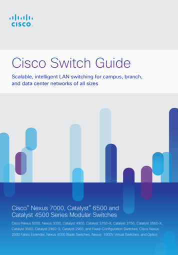
Installing the SwitchNoteFor information on 250-W AC power supply support on the PoE-capable switch models, refer to theRelease Notes for the Cisco Catalyst 3650 Switch on Cisco.com.Attaching the BracketsUse four number-8 Phillips flat-head screws to attach the long side of each bracket to the switch in oneof these mounting positions.Figure 2Attaching the Brackets to the Switch1WRC2-640WAC223Catalyst 365048PoE 4X10G2232Catalyst 365048PoE 4X10G2347813221Rear-mounting position2Number-8 Phillips flat-head screws3Front-mounting positionCatalyst 3650 Switch Getting Started Guide12OL-29733-01
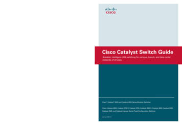
Installing the SwitchRack-Mount the SwitchUse the four number-12 Phillips machine screws to attach the brackets to the rack. Use the black Phillipsmachine screw to attach the cable guide to the left or right bracket.WarningTo prevent bodily injury when mounting or servicing this unit in a rack, you must take specialprecautions to ensure that the system remains stable. The following guidelines are provided to ensureyour safety:This unit should be mounted at the bottom of the rack if it is the only unit in the rack.When mounting this unit in a partially filled rack, load the rack from the bottom to the top with theheaviest component at the bottom of the rack.If the rack is provided with stabilizing devices, install the stabilizers before mounting or servicing theunit in the rack. Statement 1006Figure 3Attaching the Brackets to the Rack3ACTV1X13X24X25X36X1237XCatalyst365048X48PoE 34781412X2X10G41Phillips machine screw, black3Front-mounting position2Cable guide4Number-12 or number-10 Phillips machinescrewsInstall the power supply modules if needed.Catalyst 3650 Switch Getting Started GuideOL-29733-0113
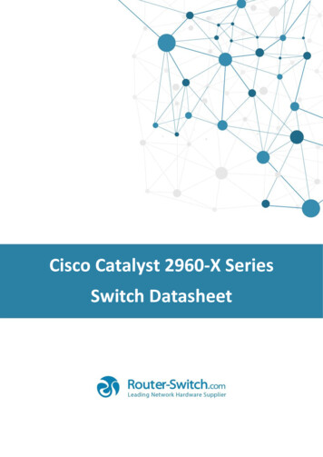
Securing the AC Power Cord (Optional)Securing the AC Power Cord (Optional)Make a loop in the power cord and thread it through the power cord retainer. Connect the power cord tothe power supply.Figure 4Securing the AC Power CordPS OK-640WACPWR-C2AC OKPS OK-250WACPWR-C2347769AC OKConnecting the StackWise CablesYou can stack the Catalyst 3650 switch with other Catalyst 3650 switches. Before connecting theStackWise cables, review the “Planning a Switch Data Stack” section in the Catalyst 3650 SwitchHardware Installation Guide. Always use Cisco-approved StackWise cables to connect the switches.CautionStep 1Removing and installing the StackWise cable can shorten its useful life. Do not remove and install thecable more often than is absolutely necessary (removing and installing it up to 200 times is supported).Remove the dust covers from the StackWise cables and store them for future use.A StackWise adapter must be installed in the StackWise port to enable stacking. The default setup is withStackWise adapter blanks installed in the StackWise ports. If StackWise stacking was ordered with theswitch, StackWise adapters are already installed in the StackWise ports, and you can proceed to step 4.Step 2Remove the StackWise adapter blanks from each destination StackWise port by unscrewing the screwson the adapter blanks using the Torx T15 Allen key provided in the stacking kit (or a Torx T15screwdriver), as shown in Figure 5. Store them for future use.Step 3Install a StackWise adapter in each destination StackWise port, and secure in place using the suppliedTorx T15 key, or a Torx T15 screwdriver, as shown in Figure 6.NoteStep 4It is not necessary to remove the fan modules prior to removal or installation of the StackWiseadapter. If the installation is performed with the system powered-on, the fans must be left in theinstalled position at all times.Connect the StackWise cable to the StackWise port on the switch rear panel.a.Align the StackWise cable connector with the StackWise adapter in the StackWise port.b.Insert it to connect the StackWise cable to the StackWise port, as shown in Figure 7. Make sure thatthe Cisco logo is on the top side of the connector.c.Finger-tighten the screws (clockwise direction).Catalyst 3650 Switch Getting Started Guide14OL-29733-01
Connecting the StackWise CablesStep 5Connect the other end of the cable to the port on the other switch and finger-tighten the screws. Avoidovertightening the screws.Figure 5Removing the StackWise Adapter Blank5CONSOLE347822MGMT42131Torx T15 screwdriver4StackWise adapter blank2Assembly screw5StackWise port3Cisco logoCatalyst 3650 Switch Getting Started GuideOL-29733-0115
Connecting the StackWise CablesFigure 6Inserting the StackWise Adapter into the StackWise Port5CONSOLE347840MGMT43121Torx T15 screwdriver4StackWise adapter2Assembly screw5StackWise port3Cisco logoFigure 7Inserting the Cable Connector into the StackWise Adapter3CONSOLE347841MGMT121StackWise cable2Cisco logo3StackWise adapter installed in a StackWise portCatalyst 3650 Switch Getting Started Guide16OL-29733-01
StackWise Cabling ConfigurationsWhen you need to remove the StackWise cable from the connector, make sure to fully unscrew thecorrect screws. When the connectors are not being used, replace the dust covers.NoteIf the StackWise cable is difficult to remove, you can use a flat-blade screwdriver to assist with removingthe cable screws. The screwdriver only works for cable removal and is designed to slip off if used forcable installation.StackWise Cabling ConfigurationsThe Catalyst 3650 switch can be stacked with other Catalyst 3650 switches.NoteYou cannot have a switch stack containing a mix of Catalyst 3850 and Catalyst 3650 switches.This illustration shows a recommended configuration making connections using 0.5-meter StackWisecables.For other configuration examples, see the Catalyst 3650 Switch Hardware Installation Guide onCisco.com at:http://www.cisco.com/go/cat3650 hwFigure 8CONSOLECONSOLECONSOLEExample of a StackWise Cabling ecting to the Switch Ports10/100/1000 or 10/100/1000 PoE PortsWhen you connect to servers, workstations, IP phones, wireless access points, and routers: Use a straight-through, twisted four-pair, Category 5 cable in a 10/100/1000 port. Use a crossover, twisted four-pair, Category 5 cable when you connect to other switches, hubs, orrepeaters.Catalyst 3650 Switch Getting Started GuideOL-29733-0117
Connecting to the Switch Ports Connect the other cable end to an RJ-45 port on the other device.In some switch models, the 10/100/1000 ports support Power over Ethernet (PoE) and PoE . Support for IEEE 802.3af compliant powered devices (up to 15.4 W) PoE Support for IEEE 802.3at compliant powered devices (up to 30 W) PoE For more details, see the Catalyst 3650 Switch Hardware Installation Guide on Cisco.com at:http://www.cisco.com/go/cat3650 hwNoteThe automatic medium-dependent interface crossover (auto-MDIX) feature is enabled by default. Theswitch detects the required cable type for copper Ethernet connections and configures the interfaces. Youcan use either a crossover or a straight-through cable for connections to a copper 10/100/1000 moduleport on the switch, regardless of the type of connected device.SFP and SFP Transceiver Module PortsUse only Cisco SFP transceiver modules with the switch. For a list of supported modules, see theCatalyst 3650 Switch Hardware Installation Guide. For detailed instructions on installing, removing,and connecting to SFP transceiver modules, see the SFP and SFP transceivers module documentation.Hold the SFP transceiver module on the sides, andinsert it into the SPF module slot on the switch untilyou feel the connector snap into place.NoteStep 2Depending on the model of the switch youare working with, the four SFP module slotscan be all 1-Gigabit SFP module slots or all10-Gigabit SFP module slots. They canalso be a combination of a pair of SFPmodules slots on the left and a pair of SFP module slots on the right. SFP module slotssupport both SFP and SFP modules.48XG1G2G3E 2X10GTE3 G4TE4Connect an appropriate cable to the module port.Catalyst 3650 4848XStep 3347772Catalyst 3650 48PoPoE 2X10GG3TE3 G4TE4347773Step 1Connect the other cable end to the other device.Catalyst 3650 Switch Getting Started Guide18OL-29733-01
TroubleshootingVerify Port ConnectivityAfter you connect a device to the switch port, the port LED turns amber for about 30 seconds while theswitch establishes a link. The LED turns green when the switch and the attached device are linked. If theLED is off, the device might not be turned on, or there might a problem with the cable or with the adapterinstalled in the device.TroubleshootingThis section includes Express Setup troubleshooting, how to reset the switch, how to access help online,and where to find more information.Express SetupIf Express Setup does not run or
AC power switches: Plug the AC power cord into the switch power supply and into a grounded AC outlet. DC power switches: See the wiring instructions in the . The switch is now in Express Setup mode. Troubleshooting: If the LEDs next to the Mode button blink when you press the button, releas