Transcription
LECTURE NOTESONKINEMATICS OF MACHINERYB.TECH IV SEMESTERPREPARED BY:Dr. K. Viswanath AllamrajuProf. V.V.S.H PrasadMECHANICAL ENGINEERINGINSTITUTE OF AERONAUTICAL ENGINEERING(Autonomous)DUNDIGAL, HYDERABAD - 500 043
UNIT IMechanics: It is that branch of scientific analysis which deals with motion, time andforce.Kinematics is the study of motion, without considering the forces which produce thatmotion. Kinematics of machines deals with the study of the relative motion of machineparts. It involves the study of position, displacement, velocity and acceleration ofmachine parts.Dynamics of machines involves the study of forces acting on the machine parts and themotions resulting from these forces.Plane motion: A body has plane motion, if all its points move in planes which areparallel to some reference plane. A body with plane motion will have only three degreesof freedom. I.e., linear along two axes parallel to the reference plane androtational/angular about the axis perpendicular to the reference plane. (eg. linear along Xand Z and rotational about Y.)The reference plane is called plane of motion. Plane motioncan be of three types. 1) Translation 2) rotation and 3) combination of translation androtation.Translation: A body has translation if it moves so that all straight lines in the body moveto parallel positions. Rectilinear translation is a motion wherein all points of the bodymove in straight lie paths. Eg. The slider in slider crank mechanism has rectilineartranslation. (link 4 in fig.1.1)Fig.1.1Translation, in which points in a body move along curved paths, is called curvilineartranslation. The tie rod connecting the wheels of a steam locomotive has curvilineartranslation. (link 3 in fig.1.2)Fig.1.2
Rotation: In rotation, all points in a body remain at fixed distances from a line which isperpendicular to the plane of rotation. This line is the axis of rotation and points in thebody describe circular paths about it. (Eg. link 2 in Fig.1.1 and links 2 & 4 in Fig.1.2)Translation and rotation: It is the combination of both translation and rotation which isexhibited by many machine parts. (Eg. link 3 in Fig.1.1)Link or element: It is the name given to any body which has motion relative to another.All materials have some elasticity. A rigid link is one, whose deformations are so smallthat they can be neglected in determining the motion parameters of the link.Fig.1.3Binary link: Link which is connected to other links at two points. (Fig.1.3 a)Ternary link: Link which is connected to other links at three points. (Fig.1.3 b)Quaternary link: Link which is connected to other links at four points. (Fig1.3 c)Pairing elements: the geometrical forms by which two members of a mechanism arejoined together, so that the relative motion between these two is consistent are known aspairing elements and the pair so formed is called kinematic pair. Each individual link of amechanism forms a pairing element.Fig.1.4 Kinematic pairFig.1.5
Degrees of freedom (DOF): It is the number of independent coordinates required todescribe the position of a body in space. A free body in space (fig 1.5) can have sixdegrees of freedom. I.e., linear positions along x, y and z axes and rotational/angularpositions with respect to x, y and z axes.In a kinematic pair, depending on the constraints imposed on the motion, the links mayloose some of the six degrees of freedom.Types of kinematic pairs:(i) Based on nature of contact between elements:(a) Lower pair. If the joint by which two members are connected has surface contact,the pair is known as lower pair. Eg. pin joints, shaft rotating in bush, slider in slidercrank mechanism.Fig.1.6 Lower pairs(b) Higher pair. If the contact between the pairing elements takes place at a point oralong a line, such as in a ball bearing or between two gear teeth in contact, it isknown as a higher pair.Fig.1.7 Higher pairs(ii) Based on relative motion between pairing elements:(a) Siding pair. Sliding pair is constituted by two elements so connected that one isconstrained to have a sliding motion relative to the other. DOF 1
(b) Turning pair (revolute pair). When connections of the two elements are such thatonly a constrained motion of rotation of one element with respect to the other ispossible, the pair constitutes a turning pair. DOF 1(c) Cylindrical pair. If the relative motion between the pairing elements is thecombination of turning and sliding, then it is called as cylindrical pair. DOF 2Fig.1.8 Sliding pairFig.1.9 Turning pairFig.1.10 Cylindrical pair(d) Rolling pair. When the pairing elements have rolling contact, the pair formed iscalled rolling pair. Eg. Bearings, Belt and pulley. DOF 1Fig.1.11 (a) Ball bearingFig.1.11(b) Belt and pulley(e) Spherical pair. A spherical pair will have surface contact and three degrees offreedom. Eg. Ball and socket joint. DOF 3(f) Helical pair or screw pair. When the nature of contact between the elements of apair is such that one element can turn about the other by screw threads, it is knownas screw pair. Eg. Nut and bolt. DOF 1
Fig.1.13 Screw pairFig.1.12 Ball and socket joint(iii) Based on the nature of mechanical constraint.(a) Closed pair. Elements of pairs held together mechanically due to their geometryconstitute a closed pair. They are also called form-closed or self-closed pair.(b) Unclosed or force closed pair. Elements of pairs held together by the action ofexternal forces constitute unclosed or force closed pair .Eg. Cam and follower.Fig.1.14 Closed pairFig. 1.15 Force closed pair (cam & follower)Constrained motion: In a kinematic pair, if one element has got only one definitemotion relative to the other, then the motion is called constrained motion.(a) Completely constrained motion. If the constrained motion is achieved by the pairingelements themselves, then it is called completely constrained motion.
Fig.1.16 Completely constrained motion(b) Successfully constrained motion. If constrained motion is not achieved by thepairing elements themselves, but by some other means, then, it is called successfullyconstrained motion. Eg. Foot step bearing, where shaft is constrained from movingupwards, by its self weight.(c) Incompletely constrained motion. When relative motion between pairing elementstakes place in more than one direction, it is called incompletely constrained motion. Eg.Shaft in a circular hole.Fig.1.17 Foot strep bearingFig.1.18 Incompletely constrained motionKinematic chain: A kinematic chain is a group of links either joined together orarranged in a manner that permits them to move relative to one another. If the links areconnected in such a way that no motion is possible, it results in a locked chain orstructure.Fig.1.19 Locked chain or structure
Mechanism: A mechanism is a constrained kinematic chain. This means that the motionof any one link in the kinematic chain will give a definite and predictable motion relativeto each of the others. Usually one of the links of the kinematic chain is fixed in amechanism.Fig.1.20 Slider crank and four bar mechanisms.If, for a particular position of a link of the chain, the positions of each of the other linksof the chain can not be predicted, then it is called as unconstrained kinematic chain and itis not mechanism.Fig.1.21 Unconstrained kinematic chainMachine: A machine is a mechanism or collection of mechanisms, which transmit forcefrom the source of power to the resistance to be overcome. Though all machines aremechanisms, all mechanisms are not machines. Many instruments are mechanisms butare not machines, because they do no useful work nor do they transform energy. Eg.Mechanical clock, drafter.Fig.1.21 DrafterPlanar mechanisms: When all the links of a mechanism have plane motion, it is calledas a planar mechanism. All the links in a planar mechanism move in planes parallel to thereference plane.
Degrees of freedom/mobility of a mechanism: It is the number of inputs (number ofindependent coordinates) required to describe the configuration or position of all the linksof the mechanism, with respect to the fixed link at any given instant.Grubler’s equation: Number of degrees of freedom of a mechanism is given byF 3(n-1)-2l-h. Where,F Degrees of freedomn Number of links n2 n3 nj, where, n2 number of binary links, n3 number of ternary links etc.l Number of lower pairs, which is obtained by counting the number of joints. If morethan two links are joined together at any point, then, one additional lower pair is to beconsidered for every additional link.h Number of higher pairsExamples of determination of degrees of freedom of planar mechanisms:(i)F 3(n-1)-2l-hHere, n2 4, n 4, l 4 and h 0.F 3(4-1)-2(4) 1I.e., one input to any one link will result indefinite motion of all the links.(ii)F 3(n-1)-2l-hHere, n2 5, n 5, l 5 and h 0.F 3(5-1)-2(5) 2I.e., two inputs to any two links arerequired to yield definite motions in all thelinks.(iii)F 3(n-1)-2l-hHere, n2 4, n3 2, n 6, l 7 and h 0.F 3(6-1)-2(7) 1I.e., one input to any one link will result indefinite motion of all the links.
(iv)F 3(n-1)-2l-hHere, n2 5, n3 1, n 6, l 7 (at theintersection of 2, 3 and 4, two lower pairsare to be considered) and h 0. F 3(6-1)2(7) 1(v)F 3(n-1)-2l-hHere, n 11, l 15 (two lower pairs at theintersection of 3, 4, 6; 2, 4, 5; 5, 7, 8; 8, 10,11) and h 0.F 3(11-1)-2(15) 0(vi) Determine the mobility of the following mechanisms.(a)(b)(c)F 3(n-1)-2l-hHere, n 4, l 5 and h 0.F 3(4-1)-2(5) -1I.e., it is a structureF 3(n-1)-2l-hHere, n 3, l 2 and h 1.F 3(3-1)-2(2)-1 1F 3(n-1)-2l-hHere, n 3, l 2 and h 1.F 3(3-1)-2(2)-1 1
Inversions of mechanism: A mechanism is one in which one of the links of a kinematicchain is fixed. Different mechanisms can be obtained by fixing different links of the samekinematic chain. These are called as inversions of the mechanism. By changing the fixedlink, the number of mechanisms which can be obtained is equal to the number of links.Excepting the original mechanism, all other mechanisms will be known as inversions oforiginal mechanism. The inversion of a mechanism does not change the motion of itslinks relative to each other.Four bar chain:Fig 1.22 Four bar chainOne of the most useful and most common mechanisms is the four-bar linkage. In thismechanism, the link which can make complete rotation is known as crank (link 2). Thelink which oscillates is known as rocker or lever (link 4). And the link connecting thesetwo is known as coupler (link 3). Link 1 is the frame.Inversions of four bar chain:Fig.1.23 Inversions of four bar chain.
Crank-rocker mechanism: In this mechanism, either link 1 or link 3 is fixed. Link 2(crank) rotates completely and link 4 (rocker) oscillates. It is similar to (a) or (b) offig.1.23.Fig.1.24Drag link mechanism. Here link 2 is fixed and both links 1 and 4 make completerotation but with different velocities. This is similar to 1.23(c).Fig.1.25Double crank mechanism. This is one type of drag link mechanism, where, links 1& 3are equal and parallel and links 2 & 4 are equal and parallel.Fig.1.26
Double rocker mechanism. In this mechanism, link 4 is fixed. Link 2 makes completerotation, whereas links 3 & 4 oscillate (Fig.1.23d)Slider crank chain: This is a kinematic chain having four links. It has one sliding pairand three turning pairs. Link 2 has rotary motion and is called crank. Link 3 has gotcombined rotary and reciprocating motion and is called connecting rod. Link 4 hasreciprocating motion and is called slider. Link 1 is frame (fixed). This mechanism is usedto convert rotary motion to reciprocating and vice versa.Fig1.27Inversions of slider crank chain: Inversions of slider crank mechanism is obtained byfixing links 2, 3 and 4.(a) crank fixed(b) connecting rod fixed(c) slider fixedFig.1.28Rotary engine – I inversion of slider crank mechanism. (crank fixed)Fig.1.29
Whitworth quick return motion mechanism–I inversion of slider crank mechanism.Fig.1.30Crank and slotted lever quick return motion mechanism – II inversion of slidercrank mechanism (connecting rod fixed).Fig.1.31
Oscillating cylinder engine–II inversion of slider crank mechanism (connecting rodfixed).Fig.1.32Pendulum pump or bull engine–III inversion of slider crank mechanism (sliderfixed).Fig.1.33
Double slider crank chain: It is a kinematic chain consisting of two turning pairs andtwo sliding pairs.Scotch –Yoke mechanism.Turning pairs – 1&2, 2&3; Sliding pairs – 3&4, 4&1.Fig.1.34Inversions of double slider crank mechanism:Elliptical trammel. This is a device which is used for generating an elliptical profile.Fig.1.35In fig. 1.35, if AC p and BC q, then, x q.cosθ and y p.sinθ.2 x Rearranging, y 222 cos 焀 sin 焀 1 . This is the equation of an ellipse. The q p path traced by point C is an ellipse, with major axis and minor axis equal to 2p and 2qrespectively.
Oldham coupling. This is an inversion of double slider crank mechanism, which is usedto connect two parallel shafts, whose axes are offset by a small amount.Fig.1.36Quick return motion mechanisms.Quick return mechanisms are used in machine tools such as shapers and power drivensaws for the purpose of giving the reciprocating cutting tool a slow cutting stroke and aquick return stroke with a constant angular velocity of the driving crank. Some of thecommon types of quick return motion mechanisms are discussed below. The ratio of timerequired for the cutting stroke to the time required for the return stroke is called the timeratio and is greater than unity.Drag link mechanismThis is one of the inversions of four bar mechanism, with four turning pairs. Here, link 2is the input link, moving with constant angular velocity in anti-clockwise direction. PointC of the mechanism is connected to the tool post E of the machine. During cutting stroke,tool post moves from E1 to E2. The corresponding positions of C are C1 and C2 as shownin the fig. 1.37. For the point C to move from C1 to C2, point B moves from B1 to B2, inanti-clockwise direction. IE, cutting stroke takes place when input link moves throughangle B1AB2 in anti-clockwise direction and return stroke takes place when input linkmoves through angle B2AB1 in anti-clockwise direction.Fig.1.37The time ratio is given by the following equation.Time for forward strokeTime for return stroke B1 AB 2 anti clockwise anti clockwise
B2 AB1Whitworth quick return motion mechanism:This is first inversion of slider mechanism, where, crank 1 is fixed. Input is given to link2, which moves at constant speed. Point C of the mechanism is connected to the tool post111D of the machine. During cutting stroke, tool post moves from D to D . The111corresponding positions of C are C and C as shown in the fig. 1.38. For the point C to111111move from C to C , point B moves from B to B , in anti-clockwise direction. I.E.,111cutting stroke takes place when input link moves through angle B O2B in anticlockwise direction and return stroke takes place when input link moves through angle111B O2B in anti-clockwise direction.Fig.1.38The time ratio is given by the following equation.Time for forward stroke B oˆ2 B 1Time for return stroke B oˆ2 B 2Crank and slotted lever quick return motion mechanismThis is second inversion of slider mechanism, where, connecting rod is fixed. Input isgiven to link 2, which moves at constant speed. Point C of the mechanism is connected to111the tool post D of the machine. During cutting stroke, tool post moves from D to D .111The corresponding positions of C are C and C as shown in the fig. 1.39. For the point111111C to move from C to C , point B moves from B to B , in anti-clockwise direction.111I.E., cutting stroke takes place when input link moves through angle B O2B in anticlockwise direction and return stroke takes place when input link moves through angle111B O2B in anti-clockwise direction.
Fig.1.39The time ratio is given by the following equation.Time for forward stroke B oˆ2 B 1Time for return stroke B oˆ2 B 2
Unit -IIKINEMATICS OF MACHINES Topic: VELOCITY ANDACCELERATION Session – I Introduction Kinematics deals with study of relative motion between the various parts of themachines. Kinematics does not involve study of forces. Thus motion leads study ofdisplacement, velocity and acceleration of a part of the machine.Study of Motions of various parts of a machine is important for determining theirvelocities and accelerations at different moments.As dynamic forces are a function of acceleration and acceleration is a function ofvelocities, study of velocity and acceleration will be useful in the design ofmechanism of a machine. The mechanism will be represented by a line diagramwhich is known as configuration diagram. The analysis can be carried out both bygraphical method as well as analytical method. Some important Definitions Displacement: All particles of a body move in parallel planes and travel by samedistance is known, linear displacement and is denoted by ‘x’.A body rotating about a fired point in such a way that all particular move incircular path angular displacement and is denoted by ‘ ’.Velocity: Rate of change of displacement is velocity. Velocity can be linear velocityof angular velocity.Linear velocity is Rate of change of linear displacement V dxdtAngular velocity is Rate of change of angular displacement d dtRelation between linear velocity and angular velocity.x r dxdt r d dtV r d dt Acceleration: Rate of change of velocity
2f dv d x Linear Acceleration (Rate of change of linear velocity)2dt dt2Thirdly dw d q Angular Acceleration (Rate of change of angular velocity)2dtdtWe also have,Absolute velocity: Velocity of a point with respect to a fixed point (zero velocitypoint).A 2O2Va 2 x rVa 2 x O2 AEx: Vao2 is absolute velocity.Relative velocity: Velocity of a point with respect to another point ‘x’B3A42O2O4Ex: Vba Velocity of point B with respect to ANote: Capital letters are used for configuration diagram. Small letters are used forvelocity vector diagram.This is absolute velocityVelocity of point A with respect to O2 fixed point, zero velocity point.B3A2
Vba or VabVba or Vab Equal in magnitude but opposite in direction.BO4Vb Absolute velocity is velocity of B with respect to O 4 (fixed point, zerovelocity point)bVbaVbO2, O4VabaVelocity vector diagramVector O2a Va Absolute velocityVector ab VabRelative velocityba VaVab is equal magnitude with Vba but is apposite in direction.Vector O4 b Vb absolute velocity.To illustrate the difference between absolute velocity and relative velocity.Let, us consider a simple situation.oA link AB moving in a vertical plane such that the link is inclined at 30 tothe horizontal with point A is moving horizontally at 4 m/s and point B movingvertically upwards. Find velocity of B.3
Va 4 m/s abAbsolute velocityHorizontal direction(known in magnitude and directors)Vb ?abAbsolute velocityVertical direction(known in directors only)VaOAoaVab4 m/s30VbCBVbaVelocity of B with respect to A is equal in magnitude to velocity of A withrespect to B but opposite in direction. Relative Velocity Equation yRigid bodyAyaRO O4xxAFig. 1 Point O is fixed and End A is a point on rigid body.Rotation of a rigid link about a fixed centre.Consider rigid link rotating about a fixed centre O, as shown in figure. Thedistance between O and A is R and OA makes and angle ‘ ’ with x-axis next linkxA R cos , yA R sin .Differentiating xA with respect to time gives velocity.4
d sin θ xA R dtdθdt - R sin Similarly,dθdyA R cos θ dtdt - R cos dxLet, d xA VAdt yA VAydtdθ angular velocity ofOA dt x VA - Rω sin yVA - Rω cos Total velocity of point A is given byVA Rw sin q 2 Rw cos θ 2VA Rω Relative Velocity Equation of Two Points on a Rigidlink Rigid body ByBR sin yAAR cos xxAxBFig. 2 Points A and B are located on rigid body5
From Fig. 2xB xA R cos yB yA R sin Differentiating xB and yB with respect to timewe get,dxB V Bx dxAdt R sin θ dθdt dxAdt R sin θ Vx R sin AdSimilarly,ddθdt VB dt R cos θ dtyByAyd yyA Rw cos θ VA Rw cos θdtVA V xyV Total velocity of point AASimilarly,AxyVB VV Total velocity of point BB BxVAyVARω cos xVA )xVA ) VA Similarly, ( R ωsin Rω cos ) Rω ( VA ( VAy(Rω sin ) VB VA(Rω sin R ωcos )yRω VAVBA VBA VB – VAVelocity analysis of any mechanism can be carried out by various methods.1. By graphical method2. By relative velocity method3. By instantaneous method6
By Graphical Method The following points are to be considered while solving problems by thismethod.1. Draw the configuration design to a suitable scale.2. Locate all fixed point in a mechanism as a common point in velocity diagram.3. Choose a suitable scale for the vector diagram velocity.r4. The velocity vector of each rotating link is to the link.5. Velocity of each link in mechanism has both magnitude and direction. Startfrom a point whose magnitude and direction is known.6. The points of the velocity diagram are indicated by small letters.To explain the method let us take a few specific examples.1. Four – Bar Mechanism: In a four bar chain ABCD link AD is fixed and in 15 cmlong. The crank AB is 4 cm long rotates at 180 rpm (cw) while link CD rotatesoabout D is 8 cm long BC AD and BAD 60 . Find angular velocity of linkCD.C15 cmB8 cmωBAo60AD15 cmConfiguration DiagramVelocity vector diagramVb r ba x AB 2πx12060Choose a suitable scale1 cm 20 m/s ab7x4 50.24 cm/sec
crV cb to CDa, dr to BCr to ABbVcb bcVc dc 38 cm/sec VcdWe know that V ω RVcd CD x CDωcD Vcd CD 838 4.75 rad/sec (cw)2. Slider Crank Mechanism:In a crank and slotted lever mechanism crank rotates of 300 rpm in a counterclockwise direction. Find(i)Angular velocity of connecting rod and(ii)Velocity of slider.A60 mm45150 mmoBConfiguration diagramStep 1: Determine the magnitude and velocity of point A with respect to 0,VA O1A x O2A 2π x 300x 6060 600 mm/secStep 2: Choose a suitable scale to draw velocity vector diagram.8
arVar to AB to OAbOAlong sides BVelocity vector diagramVab ab 1300mm/sec ba VbaBA1300 150 8.66 rad/secVb ob velocity of sliderNote: Velocity of slider is along the line of sliding.3. Shaper Mechanism:In a crank and slotted lever mechanisms crank O 2A rotates at rad/sec inCCW direction. Determine the velocity of slider.6DScale 1 cm x . m5Cω3BO224O1Configuration diagram9
Scale 1 cm x . m/saVAO2 VAVBAcbVBO1VDCdO1O2Velocity vector diagramVa w2 x O2AOb Oc1 1O1 BO1 CTo locate point C\1Oc 1OæOCöçbçè 1OB1øTo Determine Velocity of RubbingTwo links of a mechanism having turning point will be connected by pins.When the links are motion they rub against pin surface. The velocity of rubbing ofpins depends on the angular velocity of links relative to each other as well asdirection.For example: In a four bar mechanism we have pins at points A, B, C and D.\ Vra wab x ratios of pin A (rpa) sign is used wab is CW and Wbc is CCW i.e. when angular velocities are inopposite directions use sign when angular velocities are in some directions use -vesign.Vrb ( ab bc) radius rpbVrC ( bc cd) radius rpcVrD cd rpd10
Problems on velocity by velocity vector method (Graphical solutions)Problem 1:In a four bar mechanism, the dimensions of the links are as given below:AB 50 mm,BC 66 mmCD 56 mmandAD 100 mmoAt a given instant when DAB 60 the angular velocity of link AB is 10.5rad/sec in CCW direction.Determine,i)Velocity of point Cii)Velocity of point E on link BC when BE 40 mmiii)The angular velocity of link BC and CDiv)The velocity of an offset point F on link BC, if BF 45 mm, CF 30 mm and BCF is read clockwise.v)The velocity of an offset point G on link CD, if CG 24 mm, DG 44 mm and DCG is read clockwise.vi)The velocity of rubbing of pins A, B, C and D. The ratio of thepins are 30 mm, 40 mm, 25 mm and 35 mm respectively.Solution:Step -1: Construct the configuration diagram selecting a suitable scale.Scale: 1 cm 20 mmCGBF60oADStep – 2: Given the angular velocity of link AB and its direction of rotation determinevelocity of point with respect to A (A is fixed hence, it is zero velocity point).Vba BA x BA 10.5 x 0.05 0.525 m/s11
Step – 3: To draw velocity vector diagram choose a suitable scale, say 1 cm 0.2 m/s. First locate zero velocity points. r Draw a line to link AB in the direction of rotation of link AB (CCW)equal to 0.525 m/s. bVba 0.525 m/se, ga, dfC Ved rrFrom b draw a line to BC and from d. Draw d line to CD to interest at C. Vcb is given vector bc Vbc 0.44 m/s Vcd is given vector dc Vcd 0.39 m/s Step – 4: To determine velocity of point E (Absolute velocity) on link BC, firstlocate the position of point E on velocity vector diagram. This can be done by takingcorresponding ratios of lengths of links to vector distance i.e.be BEbc BC be BEx Vcb BC0.0660.04x 0.44 0.24 m/sJoin e on velocity vector diagram to zero velocity points a, d / vector de Ve 0.415 m/s.Step 5: To determine angular velocity of links BC and CD, we know V bc and Vcd. Vbc ω BC x BC ωBC Similarly,Vbc 0.44 BC 0.066 6.6 r / s . (cw)Vcd ωCD x CD ωCD Vcd 0.39 CD 0.056 6.96 r / s (CCW)Step – 6: To determine velocity of an offset point Fr Draw a line to CF from C on velocity vector diagram. 12
r Draw a line to BF from b on velocity vector diagram to intersect thepreviously drawn line at ‘f’. From the point f to zero velocity point a, d and measure vector fa to get Vf 0.495 m/s.Step – 7: To determine velocity of an offset point. r Draw a line to GC from C on velocity vector diagram. r Draw a line to DG from d on velocity vector diagram to intersectpreviously drawn line at g. Measure vector dg to get velocity of point G. Vg dg 0.305 m / sStep – 8: To determine rubbing velocity at pins Rubbing velocity at pin A willbe Vpa ab x r of pin A Vpa 10.5 x 0.03 0.315 m/s Rubbing velocity at pin B will be Vpb ( ab cb) x rpb of point at B. [ ab CCW and cbCW] Vpb (10.5 6.6) x 0.04 0.684 m/s. Rubbing velocity at point C willbe 6.96 x 0.035 0.244 m/s Problem 2:In a slider crank mechanism the crank is 200 mm long and rotates at 40rad/sec in a CCW direction. The length of the connecting rod is 800 mm. When theocrank turns through 60 from Inner-dead centre.Determine,i)The velocity of the sliderii)Velocity of point E located at a distance of 200 mm on the connectingrod extended.iii)The position and velocity of point F on the connecting rod having theleast absolute velocity.iv)The angular velocity of connecting rod.13
v)The velocity of rubbing of pins of crank shaft, crank and cross headhaving pins diameters 80,60 and 100 mm respectively.Solution:Step 1: Draw the configuration diagram by selecting a suitable scale.EAFo45BOGVa Woa x OAVa 40 x 0.2Va 8 m/sStep 2: Choose a suitable scale for velocity vector diagram and draw the velocityvector diagram. Mark zero velocity point o, g. r Draw oa to link OA equal to 8 m/s eaScale: 1 cm 2 m/sfbo, gr From a draw a line to AB and from o, g draw a horizontal line (representingthe line of motion of slider B) to intersect the previously drawn line at b. ab give Vba 4.8 m/sec BEStep – 3: To mark point ‘e’ since ‘E’ is on the extension of link AB drawn be x ab mark the point e on extension of vector ba. Join e to o, g. ge will giveABvelocity of point E.Ve ge 8.4 m/sec14
Step 4: To mark point F on link AB such that this has least velocity (absolute).rDraw a line to ab passing through o, g to cut the vector ab at f. From f too, g. gf will have the least absolute velocity. To mark the position of F on linkAB. Find BF by using the relation. fb abBFBF ABfbx AB 200mmabStep – 5: To determine the angular velocity of connecting rod.We know that Vab ab x AB ab Vab 6 rad/secABStep – 6: To determine velocity of rubbing of pins. Vpcrankshaft ao x radius of crankshaft pin 8 x 0.08 0.64 m/s VPcrank pin ( ab oa) rcrank pin (6 8)0.06 0.84 m/sec VP cross head ab x rcross head 6 x 0.1 0.6 m/sec 15
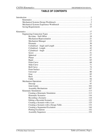
Problem 3: A quick return mechanism of crank and slotted lever type shapingmachine is shown in Fig. the dimensions of various links are as follows. O1O2 800 mm, O1B 300 mm, O2D 1300 mm and DR 400 mmoThe crank O1B makes an angle of 45 with the vertical and relates at 40 rpmin the CCW direction. Find: i)Velocity of the Ram R, velocity of cutting tool, andii)Angular velocity of link O2D.Solution: Step 1: Draw the configuration diagram.RR200DToolDB on orank, O, BBO1C on O2D452O1O2O2Step 2: Determine velocity of point B.Vb O1B x O1B O1B 2 N O1B2 x 40 6060Vb 4.18 x 0.3 1.254 m/sec16 4.18 rad / secoC
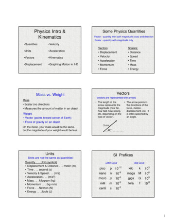
Step 3: Draw velocity vector diagram.Choose a suitable scale 1 cm 0.3 m/secbdcO1O2rro Draw O1b to link O1B equal to 1.254 m/s.o From b draw a line along the line of O 2B and from O1O2 draw a line rto O2B. This intersects at c bc will measure velocity of sliding of sliderand O2C will measure the velocity of C on link O2C.o Since point D is on the extension of link O2C measure O2d such thatO2d O2CO2 D. O2d will give velocity of point D.O2 Cro From d draw a line to link DR and from O1O2. Draw a line along theline of stroke of Ram R (horizontal), These two lines will intersect atpoint r O2 r will give the velocity of Ram R.o To determine the angular velocity of link O2D determine Vd O2d .We know that Vd O2D x O2D.O2d r/sO2DO2d17
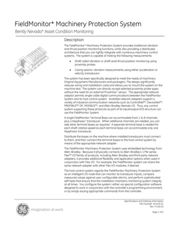
Problem 4: Figure below shows a toggle mechanisms in which the crank OArotates at 120 rpm. Find the velocity and acceleration of the slider D. Solution: 120All the dimensions in mm45oA40190100135B120DConfiguration DiagramStep 1:
crank mechanism. Fig.1.6 Lower pairs (b) Higher pair. If the contact between the pairing elements takes place at a point or along a line, such as in a ball bearing or between two gear teeth in contact, it is known as a higher pair. Fig.1.7 Higher pairs (ii) Based on r