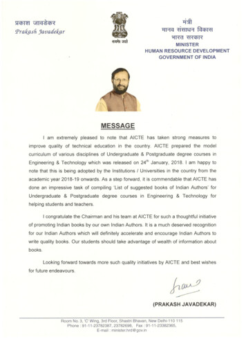
Transcription
ELECTRICAL ANDELECTRONICSENGINEERING
LIST OF 301818EE3019Course NameBasic Electrical EngineeringBasic Electrical Engineering LaboratoryBasic Electrical and Electronics EngineeringBasic Electrical and Electronics Engineering LaboratoryElectrical Workshop PracticesElectrical Circuit AnalysisNetwork TheoryAnalog Electronic CircuitsAnalog Electronic Circuits LaboratoryElectromagnetic FieldsElectrical Machines – IElectrical Machines - I LaboratoryElectrical Machines – IIElectrical Machines – II LaboratoryPower ElectronicsPower Electronics LaboratoryPower Systems – IPower Systems – I LaboratoryPower Systems – IIPower Systems – II LaboratoryWind and Solar Energy SystemsWind and Solar Energy LaboratoryIndustrial MechatronicsElectric Machines and DrivesElectric Machines and Drives LaboratoryElectrical Machines and Power SystemsEnergy EngineeringPhotovoltaic SystemsEnergy Management and AuditWind EnergySolar Energy LaboratoryElectric Drives Laboratory for Renewable EnergyWind Energy LaboratoryPower Engineering Simulation LaboratorySolar Thermal Energy ConversionMaterials for Solar PowerSolar Cell and Module TechnologyGrid Converters for Solar and Wind Power SystemsBiomass EnergyWaste to Energy ConversionOceanic EnergyData Mining for Renewable Energy SystemsPower Conversion and Control of Wind Energy SystemsPower Quality Issues and MitigationDistributed Generation and Micro gridElectrical and Electronics 134331.5431313131313133133333222233333333333
ber Physical Systems Approach To Smart GridSmart Power Grid Renewable Energy SystemsElectric and Hybrid VehiclesDisaster ManagementBasic Electrical Engineering3:0:03:0:03:0:03:0:0L3T13330P0C4Course Objectives:1. To impart the basic knowledge about the DC, AC and Magnetic circuits.2. To comprehend the working of various Electrical Machines.3. To know about various power converters and electrical installations.Course Outcomes:At the end of this course students will demonstrate the ability to1. Describe the basic terminologies of DC, AC circuits.2. Define the basic concepts of Magnetic circuits and transformers.3. Predict and analyze the behavior of any circuits.4. Identify the type of electrical machine used for required application.5. Classify various means of power conversion methodologies.6. Plan electrical wiring, earthing for house hold and commercial purposes.Module 1: DC Circuits (10 hours)Electrical circuit elements (R, L and C), voltage and current sources, Kirchoff’s laws, analysis of simplecircuits with DE excitation. Superposition, Thevenin and Norton Theorems, Time-domain analysis of firstorder RL and RC circuits.Module 2: AC Circuits (12 hours)Representation of sinusoidal waveforms, peak and RMS values, phasor representation, real power, reactivepower, apparent power, power factor. Analysis of single-phase AC circuits consisting of R, L, C, RL, RC,RLC combinations (series and parallel), resonance. Three phase balanced circuits, voltage and currentrelations in star and delta connections. Introduction to Three phase system.Module 3: Magnetic Circuits & Transformers (8 hours)Magnetic materials, B-H characteristics, Basics of ideal and practical transformer, equivalent circuit, lossesin transformers, regulation and efficiency. Auto-transformer and three-phase transformer connections.Module 4: Electrical Machines (10 hours)Construction, working principle, types and applications of DC Generator, DC Motor, Three phase & SinglePhase Induction Motor, Synchronous Generator, Stepper Motor and Servo Motor.Module 5: Introduction to Android Platform (11 hours)Introduction to Android platform – UI widgets – UI managers – different devices &drawables – Intents &fragments – styles and themes – data storages – Asynctask – Broadcast receiver notification and GCM –applicationsModule 6: Electrical Installations (9 hours)Components of LT Switchgear: Switch Fuse Unit (SFU), MCB, ELCB, MCCB, Types of Wires and Cables,Earthing. Types of Batteries, Important Characteristics for Batteries. Elementary calculations for energyconsumption, power factor improvement and battery backupText Books:1. Kothari D. P, NagrathI. J., “Basic Electrical Engineering”, Tata McGraw Hill, 2010.2. Kulshreshtha D. C., “Basic Electrical Engineering”, McGraw Hill, 2011Reference Books1. L. S. Bobrow, “Fundamentals of Electrical Engineering”, Oxford University Press, 2011.2. E. Hughes, “Electrical and Electronics Technology”, Pearson, 2010.3. Vincent Del Toro, “Electrical Engineering Fundamentals”, Prentice Hall India, 2nd Edition, 2013.Electrical and Electronics Engineering
4. Bhattacharya. S. K, “Basic Electrical and Electronics Engineering”, Pearson Education, New Delhi,2011.5. lop-an-android-app-in-10-hours18EE1002Basic Electrical Engineering LaboratoryL0T0P2C1Co-requisite: 18EE1001 Basic Electrical EngineeringCourse Objectives:1. To learn the basic safety of electrical engineering and measuring instruments.2. To know the working of various AC, DC Circuits and Electrical Machines.3. To be familiar with various power converters and electrical installations.Course OutcomesAt the end of this course students will demonstrate the ability to1. Get an exposure to common electrical components and their ratings.2. Make electrical connections by wires of appropriate ratings.3. Understand the usage of common electrical measuring instruments.4. Understand the basic characteristics of transformers and electrical machines.5. Get an exposure to the working of Switchgears.6. Get an exposure to use of Android and projects with android.Description:The laboratory will demonstrate the student about the certain basic concepts in electrical engineering.List of experiments:1. Study of basic safety precautions; Introduction and use of measuring instruments – voltmeter,ammeter, multi-meter, oscilloscope. Real-life resistors, capacitors and inductors.2. Measuring the steady-state and transient time-response of R-L, R-C, and R-L-C circuits to a stepchange in voltage (transient may be observed on a storage oscilloscope).3. Sinusoidal steady state response of R-L, and R-C circuits – impedance calculation and verification.4. Stair case wiring, Fluorescent tube light wiring, Comparison of LED and CFL wiring.5. Observation of phase differences between current and voltage, Resonance in R-L-C circuits.6. Demonstration of cut-out sections of machines: DC machine, Induction machine, Synchronousmachine and single-phase induction machine.7. Android / Arduino based Projects.8. Torque Speed Characteristic of separately excited DC motor.9. Torque-Slip Characteristic of an Induction motor.10. Study of Components of LT switchgear.18EE1003Basic Electrical and Electronics EngineeringL3T1P0C4Course Objective1. To impart knowledge on the fundamental laws of electrical circuits and the different componentsand functions of electrical machines.2. To impart knowledge on electrical measurements and wiring.3. To impart knowledge on the principles of digital electronics and fundamentals of electrondevices.Course OutcomeAt the end of the course, the student will be able to1. Define the parameters, illustrate the behavior and solve a given electric circuits.2. Name the parts, explain the operation and select a suitable electrical machine for an application.Electrical and Electronics Engineering
3. Explain the measurement of both electrical and non-electrical parameters with modern sensors andselect a suitable sensor for an application.4. Plan electrical wiring, earthing for house hold and commercial purposes.5. Explain the characteristics of electron devices.6. Explain the operation of a digital circuit.Module 1: Basic Circuits (10 hours)Fundamental laws of electric circuits - Current and Voltage sources - Source Transformation - ResistiveCircuits: Series and Parallel, Voltage and Current Division – Kirchoff’s Voltage and Current law – Star –Delta transformation – Capacitance – Inductance – Power and Power factor - Single Phase and Three PhaseBalanced circuits.Module 2: Electrical Machines (10 hours)Construction - Principle of operation - Characteristics - Applications of DC Generators, DC Motors, SinglePhase and Three Phase Induction Motor, Synchronous Generator and Motor, Stepper Motor, ServomotorModule 3: Electrical Measurements (10 hours)Measurement of Voltage – Current – Power – Energy – Power factor - Temperature Sensor – PressureSensor – Force Sensor – Load cell - Anemometer – Fire Sensor – Smoke Detector – Concentration of CO2and CO – Electronic nose -Data LoggersModule 4: Electrical Installations (10 hours)Components of LT Switchgear: Switch Fuse Unit (SFU), MCB, ELCB – Types of Wiring and WiringAccessories – House Wiring – Industrial Wiring – Earthing – PCB fabrication - Batteries – Characteristics– Energy consumption calculations – Power factor improvement – Battery BackupModule 5: Electron Devices (8 hours)Introduction - Characteristics of PN Junction diode - Zener Effect - Zener Diode and its Characteristics –Photo Diode – Light Emitting Diode (LED) - Bipolar Junction Transistor - CB, CE, CC Configurations andcharacteristics – Field Effect Transistor (FET) – MOSFETModule 6: Digital Electronics (12 hours)Binary Number System-Boolean Algebra theorems, Digital Circuits, Introduction to sequential circuits,Flip flops, Registers and counters, A/D and D/A Conversion.Text Book:1. Kothari D. P., Nagrath I. J., “Basic Electrical and Electronics Engineering”, Tata McGraw Hill,2017.Reference Books:1. Edward Hughes, “Electrical and Electronics Technology”, Pearson Education India, 10 th Edition,2010.2. Muthusubramanian R &Salivahanan S, “Basic Electrical and Electronics Engineering”, McGrawHill India Limited, New Delhi, 2014.3. Bhattacharya. S. K, “Basic Electrical and Electronics Engineering”, Pearson Education, New Delhi,2011.4. Jegathesan. V, Vinoth Kumar. K., Saravanakumar. R, “Basic Electrical & ElectronicsEngineering”, Wiley India Private Limited, New Delhi, 2011.LBasic Electrical and Electronics Engineering0LaboratoryCo-requisite: 18EE1003 Basic Electrical and Electronics EngineeringCourse Objective:1. To impart practical knowledge on basics of Electrical Engineering.2. To impart practical knowledge on basics of Electronics Engineering.3. To impart knowledge on selection of electrical and electronic components.Course Outcomes:18EE1004Electrical and Electronics EngineeringT0P2C1
At the end of the course, the students will be able to1. Verify the basic laws of an electric circuit.2. Demonstrate the working of an Electrical Machine and compute the performance factors of thesame.3. Measure the electrical parameters and select suitable sensors for an application.4. Perform domestic and industrial wiring5. Verify the characteristics of Electronic Devices.6. Construct a digital circuit.Description:The laboratory will demonstrate the student about the certain concept in electrical and electronicsengineering.List of Experiments (Any Eight from the list)1. Verification of Kirchoff’s Voltage Law and Kirchoff’s Current Law2. Measurement of Power, Energy and Power Factor3. Load characteristics of a DC Shunt Motor4. Study of sensors5. Domestic Wiring6. Industrial Wiring7. PCB Fabrication8. Identification, Specification and Testing of Active Devices (Diodes, BJT, MOSFET)9. Study and operation of Digital Multimeter, Signal Generator, Regulated Power Supply and CathodeRay Oscilloscope10. Characteristics of PN Diode and Zener Diode11. Half Wave and Full Wave Rectifier12. Control of MOSFET with IC741 OP-AMP13. Square Wave Generation using IC 555 Timer14. Study of Logic Gates15. Study of Flip Flops18EE1005Electrical Workshop PracticesL1T0P4Course Objective:1. To impart practical knowledge on control and troubleshooting of electrical gadgets.2. To impart practical knowledge on PCB fabrication.3. To impart knowledge on fitting, welding and electrical wiring.Course Outcomes:At the end of the course, the students will be able to1. Identify and understand importance of control circuits of various electrical equipment.2. Understand the basic construction and operation of various laboratory experiments.3. Develop basic PCB layout design.4. Perform basic maintenance and troubleshooting of household equipment, energy savings etc.5. Understand the use of various welding and fitting practices.6. Understand the basics of electrical wiring.Description:The laboratory will demonstrate the student about the concepts of electrical workshop practices.List of Experiments (Any twelve from the list)1. Study of simple electrical circuit diagrams and wiring2. Study of electrical connection of basic electrical equipmentElectrical and Electronics EngineeringC3
3. Study of handling of all measuring instruments and Oscilloscope (Multimeter, Wattmeter,Clamp meter, ammeter, voltmeter, CRO, DSO etc)4. Study of Electrical Cables, HRC Fuse, MCB. simple relay and Contactors5. Study of Drilling/Grinding/Winding Machines6. Assembling and Identification of Various parts, wiring, tracing of various controls, electroniccircuits of Mixer/Vacuum Cleaner/Drier7. Troubleshooting of Electric Motors8. Study of control circuit of UPS9. Study of control circuit of Home Inverter and solar inverters10. Earthing11. Fault Identification of Control Switches and in Semi-automatic Washing Machine12. Measurement of Insulation resistance and earth resistance using Meggar13. PCB layout design using software.14. PCB fabrication, Components soldering and Trouble shooting15. Simple exercises on Fitting16. Simple Exercises on Welding18EE2001Electrical Circuit AnalysisL3T1P0C4Course Objectives:1. To impart basic knowledge about electric circuits and networks to the students.2. To develop in students the ability to analyze various types of electric circuits and networks.3. To make the students understand the various network theorems and its usage in analyzing thecircuits and networksCourse Outcome:At the end of the course students will be able to1. Name the various circuit elements, explain the behavior of circuit elements and circuits and analyzethe circuits using KVL, KCL, Mesh analysis and Nodal analysis techniques.2. State various network theorems, explain it and use it for solving the problems of electric circuitsand networks.3. Relate first order and second order differential equations to electric circuits and networks, explainit, solve it for obtaining the transient responses of RL, RC and RLC networks and categorize RLCNetworks4. Describe fundamental concepts used in single phase and three phase AC circuits and coupledcircuits, explain these concepts, and solve problems pertaining to these circuits.5. Explain the Laplace transform technique, transformed networks and resonance in electric circuits,use the Laplace transform technique for transforming a network to S domain and analyzing it, andexamine the behavior of resonant circuits and assess the performance of tuned coupled circuits.6. Calculate the network parameters, explain the network parameters and identify(analyze) thenetwork parameters for a two-port network and construct interconnected networks.Module 1- Mesh and Nodal Analysis (7 hours)Analysis with dependent voltage source and current sources. Node and Mesh analysis. Concept of dualityand dual networksModule 2 -Network Theorems (10 hours)Superposition theorem, Thevinin’s theorem, Norton’s theorem, Maximum power transfer theorem,Reciprocity theorem, Compensation Theorem.Module 3 -Solution of First Order and Second Order Networks (8 hours)Solution of first order and second order differential equation for series and parallel R-L, R-C and R-L-Cnetworks. Initial and final conditions in network elements. Forced and free responses, Time constants,Steady state and transient state responses.Electrical and Electronics Engineering
Module 4- Sinusoidal Steady State Analysis (11 hours)Representation of Sine function as a rotating phasor, phasor diagrams, impedances and admittances. ACcircuit analysis, Effective or RMS value, Average power and complex power. Three phase circuits-.Coupled circuits- Dot convention in coupled circuits, Ideal transformer.Module 5 -Electric Circuit Analysis Using Laplace Transform (9 hours)Review of Laplace Transform. Analysis of Electric Circuits using Laplace transform for standard inputs,Convolution integral, Inverse Laplace transform, Transformed network with initial condition. Transferfunction representation. Poles and zeros. Frequency response (Magnitude and phase plot). Series andparallel resonances.Module6 -Two port network and Network Functions (15 hours)Two port networks, terminal pairs, Relationship of two port variables, Impedance parameters, Admittanceparameters, Transmission parameter and Hybrid Parameters. Interconnection of two port networks.Text Books1. William H. Hayt Jr, Jack E. Kemmerly and Steven M. Durbin, “Engineering Circuits Analysis”,Tata McGraw Hill Publishing Company Limited, New Delhi, 8thEdition, 2013.2. Sudhakar A., Shyammohan S Palli, “Circuits & Networks: Analysis and Synthesis”, Tata McGrawHill Publishing Company Limited, New Delhi, 3rd Edition, 2006.Reference Books:1. Joseph A. Edminister, Mahmood Nahri, “Electric Circuits”, Schaum’s series, Tata McGraw-HillPublishing Company Limited, New Delhi, 2010.2. Van Valkenburg M.E., “Network Analysis”, Pearson Education India, 3rd Edition, 2015.3. Roy Choudhuri D., “Networks and Systems”, New Age International Private Limited, 2nd Edition,2013.4. Alexander C.K., SadikuM.N.O., “Fundamentals of Electric Circuits”, McGraw Hill EducationSeries, New York, 5th Edition, 20135. Murthy K.V.V., Kamath M.S., “Basic Circuit Analysis”, Jaico Publications, 1st Edition, 2002.18EE2002Network TheoryL3T0P0C3Course Objectives:1. To impart knowledge on solving circuits using basic laws and network theorems.2. To apply mathematical methods such as Fourier series, Fourier transform and Laplace transformsto solve network and circuits problems.3. To analyze two port networks, three phase circuits and to educate on designing the filters.Course Outcomes:At the end of this course students will demonstrate the ability to1. Understand basics electrical circuits with nodal and mesh analysis.2. Apply the various electrical network theorems to analyze the circuits and networks.3. Analyze three phase circuits.4. Apply Laplace Transform for steady state and transient analysis.5. Analyze the frequency domain techniques.6. Determine different network functions and Design filter circuits to satisfy design specifications.Module 1: Network Solution methods (5 hours)Kirchhoff’s Laws, Current Division rule and voltage division rule, Node and Mesh Analysis, Matrixapproach of network containing voltage and current sources, source transformation, Wye -DeltaTransformation.Module 2: Network theorems (8 hours)Superposition, Thevenin’s, Norton’s, Maximum power Transfer, Reciprocity, Compensation andTellegen's theorem as applied to A.C. Circuits, Duals and duality.Electrical and Electronics Engineering
Module 3: Steady State analysis (7 hours)Steady state sinusoidal analysis using phasors of RLC circuits, Three-phase unbalanced circuit and powercalculation; steady state response of a network to non-sinusoidal periodic inputs, power factor, effectivevalues, Fourier transform and continuous spectra.Module 4: Network solutions using Laplace Transforms (7 hours)Laplace transforms and properties: Partial fractions, singularity functions, waveform synthesis, analysis ofRC, RL, and RLC networks with and without initial conditions with Laplace transforms evaluation of initialconditions, convolution theorem.Module 5: Transient Analysis and Resonance (7 hours)Transient behavior of simple RLC circuits, concept of complex frequency, Driving points and transferfunctions, poles and zeros of admittance function, their properties, sinusoidal response from pole-zerolocations. Behaviors of series and parallel resonant circuits,Module 6: Two port Network, Resonance, Network Graphs and Filters (11 hours)Two four port network and interconnections, Network Graphs – Tie-set and Cut-set matrix, Introduction toband pass, low pass, high pass and band reject filters.Text Books1. William H. Hayt, “Engineering Circuit Analysis” 8th Edition, McGraw-Hill Education, 2013.2. Sudhakar A., Shyammohan S Palli, “Circuits & Networks: Analysis and Synthesis”, Tata McGrawHill Publishing Company Limited, New Delhi, 3rd Edition, 2006.Reference Books1. Joseph A. Edminister, Mahmood Nahri, “Electric Circuits”, Schaum’s series, Tata McGraw-HillPublishing Company Limited, New Delhi, 2010.2. Van Valkenburg M.E., “Network Analysis”, Pearson Education India, 3rdEdition, 2015.3. Roy Choudhuri D., “Networks and Systems”, New Age International Private Limited, 2ndEdition,2013.4. Alexander C.K., Sadiku M.N.O., “Fundamentals of Electric Circuits”, McGraw Hill EducationSeries, New York, 5thEdition, 20135. Murthy K.V.V., Kamath M.S., “Basic Circuit Analysis”, Jaico Publications, 1st Edition, 2002.18EE2003Analog Electronic CircuitsL3T0P0C3Course Objectives:1. To provide students with strong basics in different Electronic devices2. To provide students with strong foundation in designing circuits3. To develop confidence in designing circuits using op-ampsCourse Outcomes:At the end of the course, the student will be able to1. Explain the characteristics and applications of electronic devices such as diode, BJTs, MOSFETsand op-amp2. Compare various biasing methods for the BJT and MOSFET amplifiers3. Construct BJT and MOSFET based amplifier circuits with various configurations.4. Calculate the small signal modelling parameters for a given equivalent circuit.5. Explain the characteristics of op-amp.6. Construct op-amp based circuits for linear and nonlinear applicationsModule 1: Diode circuits (5 hours)P-N junction diode - Ideal and Practical Diode - I-V characteristics of a diode; source protection of diodereview of half-wave and full-wave rectifiers, Zener diodes, clamping and clipping circuitsElectrical and Electronics Engineering
Module 2: BJT circuits (8 hours)Structure and I-V characteristics of a BJT; BJT as a switch. BJT as an amplifier: small-signal model, biasingcircuits, current mirror; common-emitter, common-base and common- collector amplifiers; Small signalequivalent circuits, high-frequency equivalent circuitsModule 3: MOSFET circuits (7 hours)MOSFET structure and I-V characteristics. MOSFET as a switch. MOSFET as an amplifier: small-signalmodel and biasing circuits, common-source, common-gate and common-drain amplifiers; small signalequivalent circuits - gain, input and output impedances, trans- conductance, high frequency equivalentcircuitModule 4: Differential, multi-stage and operational amplifiers (8 hours)Differential amplifier; power amplifier; direct coupled multi-stage amplifier; internal structure of anoperational amplifier, ideal op-amp, non-idealities in an op-amp (Output offset voltage, input bias current,input offset current, slew rate, gain bandwidth product)Module 5: Linear applications of op-amp (9 hours)Idealized analysis of op-amp circuits. Inverting and non-inverting amplifier, differential amplifier,instrumentation amplifier, integrator, active filter, P, PI and PID controllers and lead/lag compensator usingan op-amp, voltage regulator, oscillators (Wein bridge and phase shift). Analog to Digital Conversion.Module 6: Non-Linear applications of op-amp (8 hours)Hysteretic Comparator - Zero Crossing Detector, Square-wave and triangular-wave generators. Precisionrectifier, peak detector, Monoshot.Text Books:1. A. S. Sedra and K. C. Smith, “Microelectronic Circuits”, New York, Oxford University Press, 5thEdition 20042. J. V. Wait, L. P. Huelsman and G. A. Korn, “Introduction to Operational Amplifier theory andapplications”, McGraw Hill U. S., 1992.Reference Books:1. J. Millman and A. Grabel, “Microelectronics”, McGraw Hill Education, 2nd Edition,2001.2. P. Horowitz and W. Hill, “The Art of Electronics”, Cambridge University Press, 3rd Edition, 2015.3. P. R. Gray, R. G. Meyer and S. Lewis, “Analysis and Design of Analog Integrated Circuits”, JohnWiley & Sons, 5th Edition, 2009.4. Robert Boylestad and Louis Nashelsky, “Electronic Devices and Circuit Theory” 11th Edition, 20135. Millman&Halkias, "Electronic Devices & Circuits", Tata McGraw Hill, 3rd Edition, 20106. David. A. Bell, "Electronic Devices & Circuits ", Oxford University Press, 5th Edition 2010.18EE2004Analog Electronic Circuits LaboratoryL0T0P3C1.5Co-requisite: 18EE2004 Analog ElectronicsCourse Objectives:1. To impart knowledge on various electron devices.2. To impart knowledge on various BJT circuits.3. To impart knowledge on linear IC circuits.Course Outcomes:At the end of the semester the students are able to1. Acquire a basic knowledge in solid state electronics including diodes, MOSFET, BJT, andoperational amplifier.2. Design and analyze analog electronic circuits using discrete components3. Observe the amplitude and frequency responses of common amplification circuits.Electrical and Electronics Engineering
4. Construct various analog circuits to compare experimental results in the laboratory with theoreticalanalysis.5. Design Op-Amp based Oscillator circuit.6. Design linear and nonlinear application of Op-Amp.List of Experiments:1. Diode Characteristics2. Rectifier Circuits3. Clipping and clamping circuits4. Zener diode5. Characteristics of BJT6. Transistor DC biasing circuits7. The Common Emitter Amplifier8. The common Base amplifier9. The emitter Follower10. Amplifier Frequency Response11. JFET Characteristic12. Common Source amplifier13. Instrumentation Amplifier using Op-Amp14. RC Phase Shift Oscillators using Op-Amp15. PID controller using Op-Amp16. Signal generation using Op-Amp18EE2005Electromagnetic FieldsL3T1P0C4Course Objectives:1. To give an introduction on the coordinate system and vector algebra2. To impart knowledge on electromagnetic field distribution for various configurations.3. To give a brief description on the basics of electromagnetic waves.Course Outcomes:At the end of the course the student will be able to1. Express the concept of vector calculus and to learn about the scalar and vector fields.2. Solve static electric field problems using coordinate systems3. Examine the magnetic field concepts and solve problems using the coordinate systems4. Relate the property of magnetic materials and examine the effect of force on it.5. Explain faradays law of electromagnetic induction and Maxwell’s equation for time varying fields.6. Illustrate the wave equation and its parameters for a conductor, dielectic and magnetic medium.Module 1: Review of Vector Calculus (8 hours)Vector algebra-addition, subtraction, components of vectors, scalar and vector multiplications, tripleproducts, three orthogonal coordinate systems (rectangular, cylindrical and spherical). Vector calculusdifferentiation, partial differentiation, integration, vector operator del, gradient, divergence and curl;integral theorems of vectors. Conversion of a vector from one coordinate system to another.Module 2: Static Electric Field (8 hours)Coulomb’s law, Electric field intensity, Electrical field due to point charges. Line, Surface and Volumecharge distributions. Gauss law and its applications. Absolute Electric potential, potential difference,Calculation of potential differences for different configurations. Electric dipole, Electrostatic Energy andEnergy density. Current and current density, Ohms Law in Point form, Continuity of current, Boundaryconditions of perfect dielectric materials. Permittivity of dielectric materials, Capacitance, Capacitance ofa two-wire line, Poisson’s equation, Laplace’s equation, Solution of Laplace and Poisson’s equation,Application of Laplace’s and Poisson’s equations.Electrical and Electronics Engineering
Module 3: Static Magnetic Fields (6 hours)Biot-Savart Law, Ampere Law, Magnetic flux and magnetic flux density, Scalar and Vector Magneticpotentials. Steady magnetic fields produced by current carrying conductors.Module 4: Magnetic Forces, Materials and Inductance (9 Hours)Force on a moving charge, Force on a differential current element, Force between differential currentelements, Nature of magnetic materials, Magnetization and permeability, Magnetic boundary conditions,Magnetic circuits, inductances and mutual inductances.Module 5: Time Varying Fields and Maxwell’s Equations (9 Hours)Faraday’s law for Electromagnetic induction, Displacement current, Point form of Maxwell’s equation,Integral form of Maxwell’s equations, Motional Electromotive forces. BoundaryConditions.Module 6: Electromagnetic Waves (12 Hours)Derivation of Wave Equation, Uniform Plane Waves, Maxwell’s equation in Phasor form, Wave equationin Phasor form, Plane waves in free space and in a homogenous material. Wave equation for a conductingmedium, Plane waves in lossy dielectrics, Propagation in good conductors, Skin effect. Poynting theoremConcepts of EMI and Definitions, Classification of EMI, Units of Parameters, Examples of EMI, Sourcesof EMI,EMI coupling modes - CM and DM.Text Books:1. William H.Hayt Jr., John A.Buck, “Engineering Electro Magnetics”, Tata McGraw- Hill EducationIndia Private Limited, New Delhi, ,8th Edition 2014.2.
Module 1: Basic Circuits (10 hours) Fundamental laws of electric circuits - Current and Voltage sources - Source Transformation - Resistive Circuits: Series and Parallel, Voltage and Curre


![History of Electronics electricity [Read-Only]](/img/18/history-20of-20electronics-20-20electricity.jpg)
