Transcription
Stream Crossings,Culvert CrossingsandLimited Access PointsSurvey, Design and Installation1
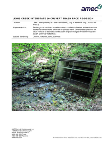
Stream CrossingA well constructed crossing can serve multiple purposes and still protect the stream from direct access bylivestock. This crossing provides access to another boundary, and provides an emergency water source for bothboundaries.2
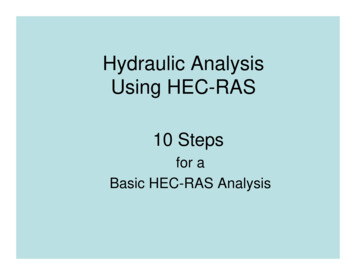
Culvert CrossingCulvert crossings also protect the streams from direct livestock access but do not have the multiple benefits of astream crossing. They are also more difficult to maintain.3
Limited AccessLimited Accesses are essentially ½ of a stream crossing. They are another method of providing water to aboundary. Other sources of water should be investigated before considering a limited access point.4
Stream Crossing Design5
Stream CrossingsA.Site Selection Considerations1.2.3.4.Location of existing crossings in fielda)Channel bottoma)6.Armor is not required on the stream bottom if it is firm and stable.Stream bank heighta)b)A higher banks equals a longer crossings which equals more expense.It also complicates locating the crossing because of the length of the ramps.a)Steep channel slopes mean higher flow velocities and will require larger baserock.Placing a crossing through an area of pooled water could result in possiblesediment deposition on the crossing.Channel slopeb)5.The landowner and/or livestock will generally find a good location for a crossing.Surrounding topographya)Will a reasonable catch point be found for the 8:1 slope or can the crossing beangled to achieve a reasonable catch point.Existing treesa)Preserve as many trees as possible to keep the stream banks stable. Alsoremoving trees means disposing of tree and root ball somewhere. All wastematerial including excavated soil will be disposed of out of the floodplain.6
Stream CrossingsB. Survey Data1.2.3.4.5.6.7.8.(print and use as a check list)Cross Section of stream along centerline of planned crossing.Profile of stream U/S and D/S of centerline.Approximate angle of turns (if any) in crossing.Stake centerline and label stakes with centerline station.Do a site investigation along streambank.Determine the “n” value of the stream or describe the channelin enough detail to determine “n” in office.Take pictures of site to document existing conditions.Draw a sketch in the field book showing:a)b)c)d)e)f)g)h)Magnetic North.TBM location and description.Stream flow direction.Centerline of crossing and direction of stationing.Existing fences or structures. (if any)Show angles on centerline (if any) and station of angle point.Planned crossing width.Location of soil borings or test pits.7
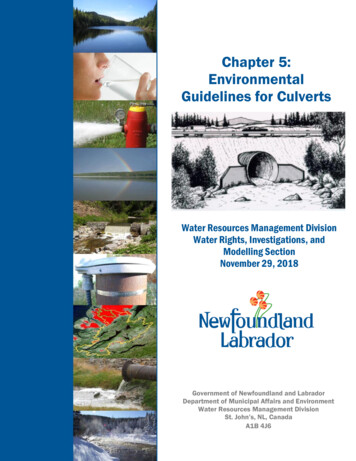
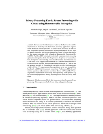
My survey notekeeping format for stream crossings. Cross section data on left page. Profile data on rightpage aligned with the station it was taken on. Sketch on bottom of left page. Centerline station of stream isnoted on sketch as well as stations with stakes set. Note that the D/S profile shot was only 45’ down streaminstead of the normal 50’. Brush was blocking the view at 50’ so it was taken (and noted) at 45”. Also theprofile shots should be taken from riffle to riffle, not in pooled or ponded water.8
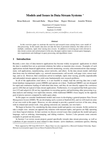
“n” Values“n” is the Channel Roughness Coefficientused in Manning's Equation.“n” varies from reach to reach of the stream. It is a measure ofhow much resistance the water flow receives from the streambed,stream shape and vegetation. Unfortunately “n” is a judgmentcall. You will have to try and select the best value for the streamyou are working on. The next slides are some examples of guidesto estimating “n”.9
10
11
C.Design DataStream Crossings(print and use as a checklist)(Having this design data will get you through the design review part of a spot check)1.2.Completed EEDrainage area map of stream3.4.5.If the stream is a designated trout stream, VGIF needs to be notified by thelandowner. (Place copy of letter notification to the landowner in design file to document this.)Copy of field notes. (Attach to design.)Plotted cross section and profile of stream.6.Cross sectional area and wetted perimeter of channel at full flow.7.8.Stream velocity calculations at full flow.Copy of design package (see below), including spec’s and O&M plan, withthe cover sheet signed by landowner and contractor. (At the least the signed(If greater than 5 sq mi a permit is required and a copy of the letter ofnotification to the landowner will document this.)(Virginia’s standard design sheets for stream crossings work well.)(Full flow defined as lowest bank elevation, for these purposes.)design with a note attached to the design stating that the spec’s and O&M plan were given to the landowner.)D.Design Package1.2.3.4.(for landowner and contractor)Completed cover sheet with location map.Completed plan view drawing of site.Completed stream crossing design sheets.Provide landowner two copies of the design, specifications and O&M plan.for landowner’s records and one for the contractor.)(One12
Drainage area using planimeterThe old fashion way still works. Copy the map and outline the drainage area. Include in design fordocumentation.13
This way is a little more modern. Again, print the drainage area map with drainage area outlined for designdocumentation.14
Standard Drawing Sheet 1The stations should be indicated at the end points and all grade changes. Station for the centerline of the stream isalso shown. If using a planimeter to determine the drainage area, the scales are very important. Please note thatNRCS Profile sheets are four lines to the inch horizontally and twenty lines to the inch vertically.15
Standard Drawing Sheet 2The centerline of crossing should be indicated on profile. The channel slope should be computed and then notedon the profile. Crossing width must be noted as well as the slope of the side slopes. Stationing should also benoted on plan view. The typical stone layer is given but can be modified by filling in different stone sizes.16
Close up of the crossing design. Don’t try to draw in the complete stone profile. Draw the top and bottom gradelines and reference the stone profile shown on sheet 2. Notice the scales on the upper left corner. Horizontally 1” 8’ and vertically 1” 4’. Different scales makes it easier to distinguish the slopes.17
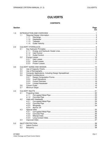
U/S Elev 98.7D/S Elev 95.5Total Distance betweenU/S and D/S points 95 ft98.7-95.5 x 100 3.4%95The stream profile is a series of survey points on the bottom of the stream channel. Plot the data here anddetermine the average bottom grade of the stream. This data is used to determine stream velocity.18
The plan view drawing assists the contractor and landowner to understand how the crossing ispositioned on the ground. It also gives fencing guidance and locations. To change the direction ofthe stream flow, “X” out the arrowheads on the flow lines and put one on the other end of the line.19
This an example of how to modify the Typical Stone Layer detail on sheet 2 to show a different stone layer.20
Location of Standard Stream Crossing Drawings on the NRCS Virginia WEB Page. 1)Click on the TechnicalResources tab, then 2)Engineering, then 3)Standard Drawings.21
When the Standard Drawing page opens 22
Click on the icon of the format you wish to download. Drawings are in three formats; Adobe PDF, AutodeskDWF, which is a free download like Adobe Reader; and Autodesk DWG.23
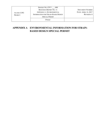
Determiningcross sectionalarea of streamchannel with aplanimeterPlanimetered Area 3.5 sq inScale: Horizontal 1” 8’Vertical1” 4’3.5 x (8 x 4) 3.5 x (32) Cross Sectional Area 112 sq ftWhen determining the cross sectional area of the stream channel with a planimeter the horizontal and verticalbecome very important. The square inches on the paper now have more square feet of area in them. Use thefollowing formula to compute the channel area. Planimetered sq. inches x (H scale x V scale) area sq. ft.24
VelocityComputationsWorksheet25
Velocity Computation Spreadsheet26
Excavation of the foundation of a crossing. Notice the vertical cut on the side. Think of the final excavation asforming a cup to put the base stone in. Place geotextile fabric over the cut and then place the base stone intothe fabric. The fabric should extend to the top of the stone layer on the sides.27
Completed crossing. All that remains to be completed is the fence installation and seeding.28
This crossing was constructed on a stream with a gravel bottom. The ramps have been excavated and armoredbut the bottom was left as it was. Why disturb the streambed if it is not necessary? Leave it alone if you can.29
Culvert Crossing Design30
Culvert CrossingsD. Site Selection Considerations1.2.3.4.5.6.7.8.Do you really want to “dam” this stream?Drainage areaQ and V of watershedWidth of stream channelBank heightEmergency spillway siteDiameter and length of culvert neededSide slopes of fill armored or not31
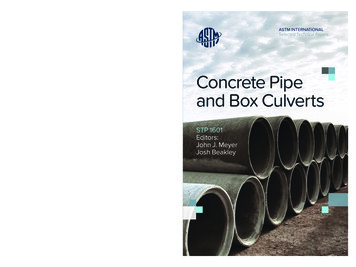
This is a nice single culvert crossing. The stone armor is place 1’ thick over non-woven geotextile fabric as overtopping protection. Notice that the trees were left undisturbed during construction.32
Crossing in fox hunting country. Notice the coops for the horses. Also notice the double spillways installed withthis culvert crossing.33
Same crossing from downstream. Notice that one tube is 6” lower then the other. This is required by our oldpermit agreement.34
Again same culvert crossing. This landowner decided to use the belled double walled PE pipe. It has a “n” factor35of 0.012, or VERY SLICK. This is a great product and well worth mentioning to the landowners. As always do notmention brands of pipe only types.
Culvert CrossingsE. Culvert Design Data1. Drainage area of stream2. Plot cross section and profile of stream3. Cross sectional area and wetted perimeter ofchannel at bank full flow4. Stream velocity at bank full flow5. Calculate culvert size based on the Q2yr. Or Callyou friendly Area Engineer.6. Complete cover sheet7. Complete plan view sheet8. Complete crossing design sheet9. Provide landowner 2 copies of design and specs36
Calculating Culvert LengthCulvert length is determined by:1.2.3.4.5.Height of fill above culverts FH (fill height)1 ftCulvert DiameterCD (culvert dia.)2 ftU/S and D/S fill slopes SS (side slope)2:1, 2:1Crossing Top Width TW (top width)16 ftPer standard. Culverts must extend 2 ftbeyond toe of slopes4 ft(((FH CD) *SS)*2) TW 4’ culvert length(((1 2)*2)*2) 16 4 32’ culvert length37
Hydraulics Formula Program.38
Single Culvert CrossingSingle culvert backfilling with gravel. Place a geotextile fabric between the subgrade and the stone. I alsohave geotextile fabric placed over the top of the stone and culvert to prevent the earth backfill from migratinginto the stone layer. VDOT # 1 size stone is also acceptable for the stone backfill.39
Double Culvert Crossing2’Double culverts backfilling with gravel. Place a geotextile fabric as mentioned in the previous slide. Aminimum space of 2’ is to be left between the culverts. This allows the contractor to consolidate the stonebackfill between the culverts. VDOT # 1 size stone is also acceptable for the stone backfill. It is alsoacceptable to completely backfill with stone.40
Single Spillway for routingheavy flows away from culvert41
Limited Access Watering Points42
Limited Access Points1.2.3.4.Are basically ½ a stream crossingUse same design criteria as stream crossingsShould be wide.12 to 16 ft minPonds accesses should extend to a depth of 2to 3 ft.5. Stream accesses should have an armoredbottom.43
44
45
46
END47
design with a note attached to the design stating that the spec’s and O&M plan were given to the landowner.) D. Design Package (for landowner and contractor) 1. Completed cover sheet wit