Transcription
TND316/DRev. 3, March-07220 W LCD TV Power Supply ReferenceDesign Featuring NCP1396 and NCP1605Documentation1
2007 ON Semiconductor.Disclaimer: ON Semiconductor is providing this reference design documentation package “ASIS” and the recipient assumes all risk associated with the use and/or commercialization of thisdesign package. No licenses to ON Semiconductor’s or any third party’s Intellectual Property isconveyed by the transfer of this documentation. This reference design documentation package isprovided only to assist the customers in evaluation and feasibility assessment of the referencedesign. It is expected that users may make further refinements to meet specific performancegoals.2
123Overview.4Introduction .5LCD TV Power Supply Requirements.53.1Standby mode .53.2Active mode.64Limitations of existing solutions .75Overcoming limitations with NCP1605 / NCP1396 / NCP1027.75.1Architecture Overview.75.2Main power supply: NCP1396 .85.2.1Half Bridge Resonant LLC topology .85.2.2Protections .95.3Standby Power Supply: NCP1027.95.3.1NCP1027 characteristics: .105.4Power Factor Correction: NCP1605 .106Specifications.107Reference Design Performance Summary .117.1Efficiency .117.2Standby Power .117.3Standards and Regulations .118Board Picture .149Schematic .1510 Board Layout .1611 Bill Of Material .2012 Appendix.2412.1 NCP1396 .2412.2 NCP1605 .2412.3 NCP1027 .2412.4 References .243
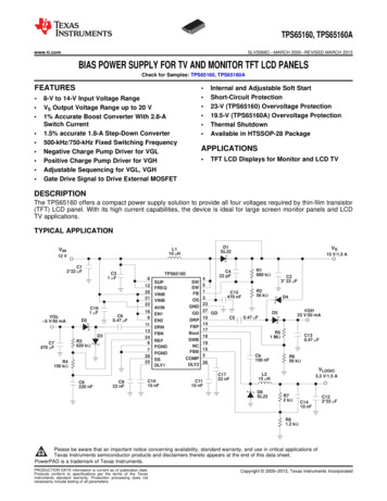
1 OverviewThis reference document describes a built-and-tested, GreenPointTM solution for an LCDTV power supply.The reference design circuit consists of one single-sided 130 mm x 200 mm printedcircuit board designed to fit into an LCD TV. Height is 25 mm.An overview of the entire circuit is provided by Figure 1. As shown in that figure, ONSemiconductor devices are available for every block of the LCD TV power supply; andby judicious choice of design tradeoffs, optimum performance is achieved at minimumcost.Figure 14
2 IntroductionFrom Tubes to Flat TVsSince 1936 when the BBC begins the world’s first public-television broadcast in London,the TV world made huge progress. A few examples: 1953: color broadcasting 1956: first VCR 1962: first television satellite (Telstar) 1981: NHK (Japan) demonstrates an HDTV systemBut “the idea of sitting in front of a box in your living room is becoming obsolete. For theTV industry, technology is creating vast opportunities”. – Newsweek, June 2005.Obviously Flat Panel Display (FPD) is one of the technologies that will drive theseopportunities: High Definition TV (HDTV). Digital TV: The analog TV signal will be shut down soon in Europe and in NorthAmerica as it is replaced by Digital Terrestrial signal. Satellite and Cable Digitaldecoders are already very common. Bigger screen, smaller form factor: Now that we all have seen these fancyscreens, who is willing to go back to the old big bulky box?FPD includes both LCD (Liquid Crystal Display) and Plasma technologies.3 LCD TV Power Supply RequirementsIn large FPD ( 30”), the power supply is generally internal as it requires from 200 W to600 W. A few voltages are needed to supply the different blocks such as backlighting,audio, video, demodulation, etc.Because the input power is above 75 W, the application has to be compliant with theIEC1000-3-2 class D standard. Power Factor Correction is therefore needed. Becausethe main power supply has to be optimized for higher efficiency and slimmer form factor,an active PFC must be implemented to limit the variation of the input voltage in front ofthe main PSU.Most of the LCD TV power supplies are designed to cope with universal mains: 85 Vacto 265 Vac, 47-63 Hz.A 5 V auxiliary power supply is needed to supply the microcontroller that must remainalive in standby mode.3.1 Standby modeHaving a low consumption in standby mode is a key requirement. Recent studies and insitu measurement campaigns have indicated that in the average EU household, between5% and 10% of its total yearly electricity consumption is due to the standby mode ofconsumer electronics equipment and other apparatus. TV sets are obviously one of thebiggest contributors.5
In 1997, the European Commission concluded a negotiated agreement with individualconsumer electronics manufacturers and the EU trade association EACEM, to reducethe stand-by losses of TVs and VCRs. In the year 2003 a new agreement for TVs andDVDs was concluded.Many initiatives have been taken around the world. And even if these requirements arenot yet standards, most of the manufacturers have already applied these rules in theirdesigns.Hereinafter the list of the most important initiatives:Region USProgram nameRequirements for TelevisionsCSCEnergy Saving3W3W1W9 W with a STBEU Eco-LabelEU Code ofConductGEEA1 Watt ExecutiveOrderDemoboardcomplianceYesYesYes3 W with a STBYes1WYes1WYesEnergy StarProduct CategoryPhase I Standby Mode(effective 7/1/02)Phase II StandbyMode (effective7/1/04)Phase III StandbyMode (effective 7/1/05)TV 3 WattsAnalog: 1 WattDigital: 3 Watts 1 WattTelevision MonitorAnalog: 1 WattDigital: 3 Watts 1 WattComponent TelevisionUnit 3 Watts 1 WattTV/VCR CombinationUnit 6 Watts 1 WattTV/DVD, VCR/DVD, andTV/VCR/DVDCombinations 4 Watts 1 Watt3.2 Active modeAccording to the American Department of Energy’s (DOE) Energy InformationAdministration (EIA), by 2015 electronics products may account for 18% of totalhousehold electricity demand – this will exceed lighting and appliances as a percent oftotal residential electricity consumption. This is linked to the fact thatTVs are ‘on’ more hours per day. According to Nielsen Media Research (NMR), for theSeptember 2004 – September 2005 viewing season, the average U.S. household wastuned into television an average of 8 hours and 11 minutes per day. And this does nottake into account additional hours that a TV is on due to peripheral devices such asgame consoles, digital video recorders, and increased availability of cable/satelliteprogramming.6
Furthermore most of the flat panel televisions being purchased by consumers willconsume double or more the active mode power of the smaller CRT televisions that theyare replacing. Much of this differential in power consumption is simply attributable to theincreased size of the products being sold now.As a consequence of these market evolutions, Energy star / EPA intend to developenergy efficiency specifications for TVs that are performance-based and technologyneutral. (See4 Limitations of existing solutionsOne of the key differentiating factors of a flat TV over a classical TV is the thickness ofthe cabinet - the thinner the better. But one must keep in mind: The amount of power to be delivered is relatively large: the number of watts percm3 is much larger compared to the one in a CRT TV. Because the TV will be used in the living room, audible noise can be a problem,and the use of fans is limited. Cost is key in the very competitive environment of the consumer electronicsworld. The panel, the power supply and the audio card are close to each other;therefore EMI and pollution could severely alter the picture and sound quality.High efficiency and a low EMI signature at a reasonable cost are required, and classicaltopologies can hardly combine these needs: Flyback: transformer usage is far from being optimal Forward: the EMI signature is not reduced to its minimum5 Overcoming limitations with NCP1605 / NCP1396 /NCP10275.1 Architecture OverviewFirst, the use of active power factor correction in the front-end allows systemoptimization because the PFC output voltage is well regulated. The implementation ofthe active PFC front end is done using the NCP1605.The SMPS stage uses a Half Bridge Resonant LLC topology. This topology offers anumber of advantages as demonstrated in the schematics and the results. It improvesefficiency, reduces EMI signature and provides better magnetic utilization. The NCP1396controller is used to implement the most effective control scheme of Half BridgeResonant LLC converter.For the standby output circuit, a higher integration level is made feasible by using theNCP1027, a PWM regulator that also incorporates an appropriate switch to provide allfunctionality in one package.In summary, the architecture selected for this reference design allows designoptimization so that the desired performance is achieved without increasing thecomponent costs and circuit complexity too much. The performance results sectiondemonstrates the performance.7
5.2 Main power supply: NCP13965.2.1 Half Bridge Resonant LLC topologyThe Half Bridge Resonant LLC topology, that is a member of the Series ResonantConverters (SRC), begins to be widely used in consumer applications such as LCD TVsor plasma display panels. In these particular applications, the output power level rangesfrom 200 W up to 600 W.The Half Bridge Resonant LLC converter is an attractive alternative to the traditional HalfBridge (HB) topology for several reasons. Advantages include: ZVS (Zero Voltage Switching) capability over the entire load range:Switching takes place under conditions of zero drain voltage. Turn-on losses arethus nearly zero and EMI signature is improved compared to the HB, whichoperates under hard-switching conditions. Low turnoff current: Switches are turned off under low current conditions, andso the turn-off losses are also lowered compared to the HB topology. Zero current turnoff of the secondary diodes: When the converter operatesunder full load, the output rectifiers are turned off under zero-current conditions,reducing the EMI signature. No increased component count: The component count is virtually the same asthe classical half bridge topology.Figure 2 is the structure of this resonant converter. A 50 % duty-cycle half-bridgedelivers high-voltage square waves swinging from 0 to the input voltage VIN to aresonating circuit. By adjusting the frequency via a voltage-controlled oscillator (VCO),the feedback loop can adjust the output level depending on the power demand.VinQbVout1Cs N:1Ls657LmCQRL9Figure 2The resonating circuit is made of a capacitor, Cs, in series with two inductors, Ls andLm. One of these inductors, Lm, represents the magnetizing inductor of the transformerand creates one resonating point together with Ls and Cs. The reflection of the load overthis inductor will either make it disappear from the circuit (Lm is fully short-circuited by areflected RL of low value at heavy load currents) or will make it stay in series with the8
series inductor Ls in light load conditions. As a result, depending on the loadingconditions, the resonant frequency will move between a minimum and a maximum:The frequency of operation depends on the power demand. For a low power demand,the operating frequency is rather high, away from the resonating point. To the contrary,at high power, the control loop reduces the switching frequency and approaches one ofthe resonant frequencies to deliver the necessary amount of current to the load.This topology behaves like a frequency dependent divider.Figure 3: Substitutive schematic of the LLC resonant converterRac 8 RLπ n 2 η2Where:RL is the real loading resistancen is the transformer turns ratioη is the expected efficiency5.2.2 ProtectionsThe NCP1396 differs from other resonant controllers thanks to its protection features.The device can react to various inputs like: Fast events input: Like an over-current condition, a need to shutdown (sleepmode) or a way to force a controlled burst mode (skip cycle at low output power). Slow events input: This input serves as a delayed shutdown, where an eventlike a transient overload does not immediately stop pulses but starts a timer. Ifthe event duration lasts longer than what the timer imposes, then all pulses aredisabled.5.3 Standby Power Supply: NCP1027A NCP1027 is used for the auxiliary flyback power supply. This power supply provides astable Vcc to supply the NCP1653, the NCP1395 and the NCP5181 under all operatingconditions, but it also supplies 5 V to the devices that must remain alive in standbymode.9
5.3.1 NCP1027 characteristics: Brown-out detection: The controller will not allow operation in low mainsconditions. You can adjust the level at which the circuit starts or stops operation.Ramp compensation: Designing in Continuous Conduction Mode helps toreduce conduction losses. However, at low input voltage (85 Vac), the duty-cyclemight exceed 50% and the risk exists to enter a subharmonic mode. A simpleresistor to ground injects the right compensation level.Over power protection: A resistive network to the bulk reduces the peak currentcapability and accordingly harnesses the maximum power at high line. As this isdone independently from the auxiliary Vcc, the design gains in simplicity andexecution speed.Latch-off input: Some PC manufacturers require a complete latch-off in thepresence of an external event, e.g., over temperature. The controller offers thispossibility via a dedicated input.Frequency dithering: The switching frequency (here 65 kHz) is modulatedduring operation. This naturally spreads the harmonic content and reduces thepeak value when analyzing the signature.5.4 Power Factor Correction: NCP1605The NCP1605 is a PFC driver designed to operate in fixed frequency, discontinuousConduction Mode (DCM). In the most stressful conditions, Critical Conduction Mode(CRM) can be achieved without power factor degradation and the circuit could be viewedas a CRM controller with a frequency clamp (given by the oscillator). Finally, theNCP1605 tends to give the best of both modes without their respective drawbacks.Furthermore, the circuit incorporates protection features for a rugged operation togetherwith some special circuitry to lower the power consumed by the PFC stage in no loadconditions.6 SpecificationsInput Voltage: Universal input 85 Vac to 265 Vac, 47-63 HzMain Power Supply Output voltages: 24 V / 6 A 12 V / 3 A 30 V / 1 AStandby Power Supply: 5 V / 2.5 A Pin 1 W when the consumption on the 5 V is 100 mA10
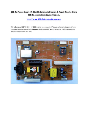
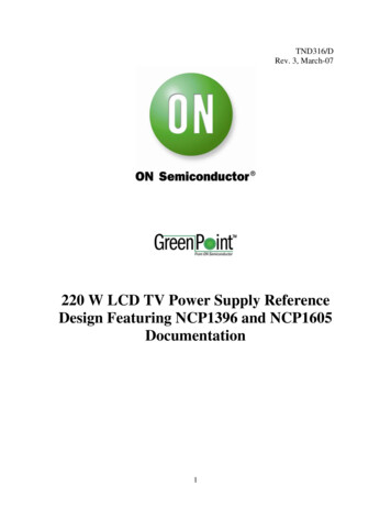
7 Reference Design Performance Summary7.1 EfficiencyTV 220W Efficiency(Load 5V/0-2.5A,30V/1A,12V/3A,24V/6A)95EFFICIENCY [%]949392919089888786858483Input [Vac] 1158281Input [Vac] D [A]7.2 Standby PowerInput VoltageStandby loadPowerconsumption115 V0.5 W0.735 W230 V0.5 W0.873 W7.3 Standards and RegulationsSpecificationEN61000-3-2 – Limits for harmonic current emissions Class D11ResultPass
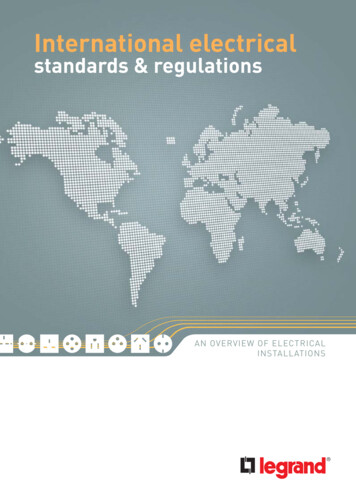
Conducted Emissions @ 230 Vac12
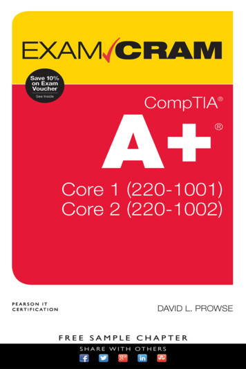
Conducted Emissions @ 110 Vac13
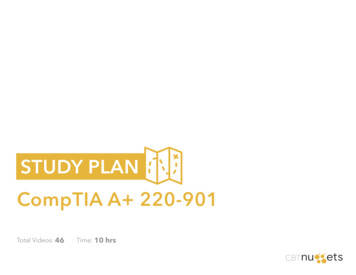
8 Board Picture14
9 Schematic15
10 Board Layout16
17
18
19
11 Bill Of MaterialDesignatorB1Quantity adFreeManufacturerManufacturer Part L470M10X20YesYesBridge rectifierKBU8M11Electrolytic capacitor470uF/35VC101Electrolytic capacitor220uF/63V10%CPOL-EUE5-10.5Rubycon63 YXA220M 10 16YesYesC111MKP 73-0.033uF 15 630VYesYesC1, C2, C3, C8, C9, C12, C13, C14,C15, C45, C461Value20%C161Electrolytic capacitor220uF/35V20%CPOL-EUE5-10.5Rubycon35 RX30220M 10 12.5YesYesC17, C23, C503Ceramic capacitor ramic BPYesYesC19, C28, C33, C34, C385C201Ceramic capacitor esYesC21, C35, C543Ceramic capacitor ramic capacitor ramic capacitor SMD390p5%C-EUC1206EpcosB37871K5391J060YesYesC25, C26, C29, C37, C40, C42, C537Ceramic capacitor eramic capacitor amic capacitor ramic capacitor ectrolytic capacitor4u7/35V20%CPOL-EUE2-5Rubycon35 MH54.7M 4 5YesYesC391Ceramic capacitor SMD2n210%C-EUC1206EpcosB37872A5222K060YesYesC4, C472Electrolytic capacitor220uF/25V20%CPOL-EUE5-10.5Rubycon25 NXA220M 10 12.5YesYesC411C431MKP 6103M289YesYesC481Electrolytic capacitor1u20%CPOL-EUE2-5Rubycon50 MH51M 4 5YesYesC491Electrolytic capacitor100uF/35V20%CPOL-EUE5.5-8Rubycon50 PK100M 8 11.5YesYesC5, C31, C443MKP 6KM410000N1MYesYesC511Electrolytic capacitor10uF/35V20%CPOL-EUE2.5-6Rubycon50 MH710M 6.3 7YesYesC521Ceramic capacitor ectrolytic capacitor100uF/450V20%EC18L40'22L35'Rubycon450 VXG100M 22 30YesYesC71Electrolytic capacitor100uF/450V20%EC18L40'22L35 90'Rubycon450 VXG100M 22 30YesYesCY1, CY2, CY33Ceramic esD1, D11, D12, D15, D185DiodeMMSD4148SOD-123ON semiconductorMMSD4148T1GNoYesD101Dual diodeMBRF20100CTTO-220ON semiconductorMBRF20100CTGNoYesD13, D22, D243DiodeMURA160SMDSMAON ments
D141D161NUZener diode3V3D171D191Zener diode7V5D21Diode1N5408SOD-1235%SOD-1235%NUON semiconductorMMSZ3V3T1GNoYesSOD-123ON semiconductorAxial Lead9.50x5.30mmON 23D201NUSMAD211DiodeMBRS340T3SMCON semiconductorMBRS320T3GD231Zener diode18VSOD-123ON semiconductorMMSZ18T1GNoYesD3, D5, D6, D7, D8, D96DiodeMBRS4201T3GSMCON 0ON semiconductorMSR860GNoYesF11FUSEHOLDER, NG 11COVER, PCB FUSEHOLDER1FUSE, MEDIUM DELAY 4A4A1HeatsingSK 454 150 SAMulticompMCHTC-150MYesYesBUSSMANNTDC 210-4AYesYesSK454/150 GNDFischer ElektronikSK 454 150 SAYesYesHEATSING 21HeatsingSK 454 100 SASK454/100 GNDFischer ElektronikSK 454 100 SAYesYesIC11PFC controllerNCP1605SOIC 16ON semiconductorNCP1605DR2GNoYesIC2, IC62Programmable Precision ReferenceTL431SO8SOIC-8ON semiconductorNCV431AIDR2GNoYesIC31Resonant controllerNCP1396ASOIC 16ON semiconductorNCP1396ADR2GNoYesIC41Programmable Precision ReferenceTLV431ASOT-23ON semiconductorTLV431ASN1T1GNoYesIC51HV Switcher for Medium Power Offline SMPSNCP1027PDIP (8 Minus Pin 6)ON semiconductorNCP1027P065GNoYesYesJ1, sYesJ51ConectorLP7.5/2/903.2 ORWeidmuellerWeidmuellerLP7.5/2/903.2 ORYesYesL11Inductor2702.0012A (260uH)10%Pulse 2702Pulse2702.0012AYesYesL21EMI 100u20%DO5040H 100CoilcraftDO5040H-104MLBYesYesOK1, OK2, OK33Opto-couplerPC817PC817SMDAVAGO TECHNOLOGIESHCPL-817-300EYesYesQ11NPN Dual General Purpose TransistorBC848CDWSOT 363 6 LEADON semiconductorBC848CDW1T1GNoYesNUTLBIQ2, Q4, Q63NPN General Purpose TransistorBC817-16LT1SOT-23ON semiconductorBC817-16LT1GNoYesQ31NPN General Purpose TransistorBC846BSOT-23ON semiconductorBC846BLT1GNoYes21
Q51R1,R33, R413NUSOT-23Resistor SMD10R1%R-EU R1206VishayRCA120610R0FKEAYesYesYesR111Resistor trough hole0.1R1%R-EU 0617/22VishayPAC300001007FAC000YesR12, R132Resistor SMD6k81%R-EU R1206VishayRCA12066K80FKEAYesYesR141Resistor SMD200k1%R-EU R1206VishayRCA120620K0FKEAYesYesR151Resistor SMD47k1%R-EU R1206VishayRCA120647K0FKEAYesYesR161Resistor SMD1k31%R-EU R1206VishayRCA12061K30FKEAYesYesR171Resistor SMD910R1%R-EU R1206VishayRCA1206910RFKEAYesYesR19, R32, R37, R39, R725Resistor SMD1k1%R-EU R1206VishayRCA12061K00FKEAYesYesR2, R62Resistor trough hole2M21%R-EU 0204/7VishayMRS16000C2204FCTYesYesR201Resistor SMD18k1%R-EU R1206VishayRCA120618K0FKEAYesYesR21, R22, R23, R494NUR-EU 2381 584 T271SYesYesR251Resistor SMD11k1%R-EU R1206VishayRCA120611K0FKEAYesYesR26, R692Resistor SMD180k1%R-EU R1206VishayRCA1206180KFKEAYesYesR271Resistor SMD5k11%R-EU R1206VishayRCA12065K10FKEAYesYesR281Resistor SMD3k31%R-EU R1206VishayRCA12063K30FKEAYesYesR291Resistor SMD470R1%R-EU R1206VishayRCA1206470RFKEAYesYesR3, R52Resistor SMD2M21%R-EU R1206VishayRCA12062M20FKEAYesYesR301Resistor SMD220k1%R-EU R1206VishayRCA1206220KFKEAYesYesR31, R712Resistor SMD100R1%R-EU R1206VishayRCA1206100RFKEAYesYesR34, R762Resistor SMD18k1%R-EU R1206VishayRCA120618K0FKEAYesYesR351Resistor SMD68k1%R-EU R1206VishayRCA120668K0FKEAYesYesR361Resistor SMD82k1%R-EU R1206VishayRCA120682K0FKEAYesYes1Resistor SMD20k1%R-EU R1206VishayRCA120620K0FKEAYesYes12Resistor SMD10k1%R-EU R1206VishayRCA120610K0FKEAYesYesR38R4, R7, R10, R18, R44, R51, R55, R56,R60, R73, R78, R79R401Resistor SMD1M1%R-EU R1206VishayRCA12061M00FKEAYesYesR421Resistor SMD51k1%R-EU R1206VishayRCA120651K0FKEAYesYesR431Resistor SMD18R1%R-EU R1206VishayRCA120618R0FKEAYesYesR451Resistor SMD2k71%R-EU R1206VishayRCA12062K70FKEAYesYesR461Resistor SMD2k21%R-EU R1206VishayRCA12062K20FKEAYesYesR471Resistor SMD3k31%R-EU R1206VishayRCA12063K30FKEAYesYes22
R481Resistor SMD5k61%R-EU R1206VishayRCA12065K60FKEAYesYesR501Resistor SMD8k21%R-EU R1206VishayRCA12068K20FKEAYesYesR521Resistor SMD12k1%R-EU R1206VishayRCA120612K0FKEAYesYesR531Resistor SMD150k1%R-EU R1206VishayRCA1206150KFKEAYesYesR541Resistor SMD15k1%R-EU R1206VishayRCA120615K0FKEAYesYesR571Resistor SMD1k51%R-EU R1206VishayRCA12061K50FKEAYesYesR581Resistor SMD6k21%R-EU R1206VishayRCA12066K20FKEAYesYesR59, R61, R623Resistor SMD820R1%R-EU R1206VishayRCA1206820RFKEAYesYesR63, R672Resistor SMD1M21%R-EU R1206VishayRCA12061M20FKEAYesYesR641Resistor SMD4k71%R-EU R1206VishayRCA12064K70FKEAYesYesR651Resistor trough hole150k1%R-EU 0207/10VishayMRS25000C1503FCTYesYesR661Resistor trough hole47R1%R-EU 0207/10VishayMRS25000C4709FCTYesYesR681Thermistor PTCCL09H191HBE is type for 230VThermistor PTCCL13H321HBE width rangePTCCL09H191HBEPTCCL13H321HBEP594Vishay2381 661 519132381 662 53213YesYesR701Resistor SMD3k91%R-EU R1206VishayRCA12063K90FKEAYesYesR741Resistor SMD360k1%R-EU R1206VishayRCA1206360KFKEAYesYesR751Resistor SMD470k1%R-EU R1206VishayRCA1206470KFKEAYesYesR771Resistor SMD75k1%R-EU R1206VishayRCA120675K0FKEAYesYesR8, R92Resistor SMDM221%R-EU R1206VishayRCA1206220KFKEAYesYesR801Resistor trough hole, high voltage4M75%R-EU 0414/15VishayVR37000004704JA100YesYesT1, T32MOSFET NM50FPYesYesT21MOSFET NM50FPYesYesTL1, TL2, TL3, esTR11Resonant R21Stand by 3
12 Appendix12.1 NCP1396 DatasheetAND8255: A Simple DC SPICE Model for the LLC ConverterExcel spreadsheet to help LLC circuit design12.2 NCP1605 DatasheetAND8281: Implementing the NCP1605 to Drive the PFC Stage of a 19 V / 8 A Power SupplyNCP1605 PFC Boost Design Worksheet12.3 NCP1027 DatasheetAND8241: A 5 V/2 A Standby Power Supply for Intel Compliant ATX ApplicationsNCP1027 Brownout Computing1 2.4 ReferencesDraft Commission Communication on Policy Instruments to Reduce Stand-by Losses of ConsumerElectronic Equipment (19 February nsumer electronics communication.pdf European Information & Communications Technology Industry Association http://www.eicta.org/ http://standby.lbl.gov/ACEEE/StandbyPaper.pdfCSC (China): http://www.cecp.org.cn/englishhtml/index.aspTop Runner (Japan): http://www.eccj.or.jp/top runner/index.htmlEU Eco-label (Europe): duct/pg television en.htmEU Code of Conduct (Europe): y initiative.htmGEEA (Europe): http://www.efficient-appliances.org/ ergy Star: http://www.energystar.gov/ http://www.energystar.gov/index.cfm?c product specs.pt product specs http://www.energystar.gov/index.cfm?c revisions.tv vcr spec1 Watt Executive Order:http://oahu.lbl.gov/ http://oahu.lbl.gov/level summary.html24
Mar 26, 2007 · 3 LCD TV Power Supply Requirements In large FPD ( 30”), the power supply is generally internal as it requires from 200 W to 600 W. A few voltages are needed to supply the different blocks such as backlighting, audio, video, demodulation, etc. Because the input power is