Transcription
Arduino Lesson 11. LCD Displays - Part 1Created by Simon sson-11-lcd-displays-1Last updated on 2021-11-15 05:52:38 PM EST Adafruit IndustriesPage 1 of 12
Table of ContentsOverview3Parts3 Part QtyBreadboard Layout8Soldering Pins to the Display9Arduino Code10Other Things to Do11 Adafruit IndustriesPage 2 of 12
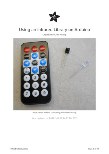
OverviewIn this lesson, you will learn how to wire up and use an alphanumeric LCD display.The display has an LED backlight and can display two rows with up to 16 characterson each row. You can see the rectangles for each character on the display and thepixels that make up each character. The display is just white on blue and is intendedfor showing text.In this lesson, we will run the Arduino example program for the LCD library, but in thenext lesson, we will get our display to show the temperature and light level, usingsensors.PartsTo build the project described in this lesson, you will need the following parts. Adafruit IndustriesPage 3 of 12
PartQtyLCD Display (16x2 characters)1 Adafruit IndustriesPage 4 of 12
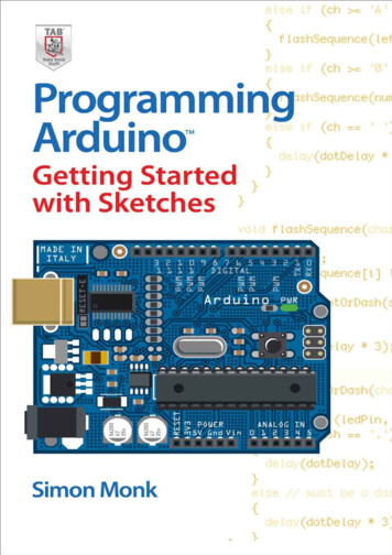
10 kΩ variable resistor (pot)1 Adafruit IndustriesPage 5 of 12
Half-size Breadboard1 Adafruit IndustriesPage 6 of 12
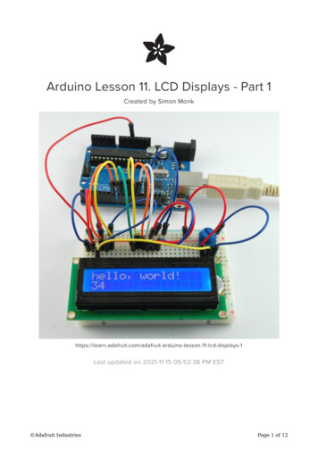
Arduino Uno R31 Adafruit IndustriesPage 7 of 12
Jumper wire pack1Breadboard LayoutThe LCD display needs six Arduino pins, all set to be digital outputs. It also needs 5Vand GND connections. Adafruit IndustriesPage 8 of 12
There are quite a few connections to be made. Lining up the display with the top ofthe breadboard helps to identify its pins without too much counting, especially if thebreadboard has its rows numbered with row 1 as the top row of the board. Do notforget, the long yellow lead that links the slider of the pot to pin 3 of the display. The'pot' is used to control the contrast of the display.You may find that your display is supplied without header pins attached to it. If so,follow the instructions in the next section.Soldering Pins to the DisplayThe display needs 16 pins, so if your header strip is longer than that then break it offto the right length. Adafruit IndustriesPage 9 of 12
Then put the length of 16 header pins into the solder tabs on the display and startingat one end, solder each of the pins in place. It can be easier to put the long end of thepins into the breadboard so that the header pins are held straight.If you do not do this, then solder one pin in first and then get the pins in straight,melting the solder on the pin before making any adjustment.Arduino CodeThe Arduino IDE includes an example of using the LCD library which we will use. Youcan find this on the File menu under Examples Liquid Crystal HelloWorld.This example uses different pins to the ones we use, so find the line of code below:LiquidCrystal lcd(12, 11, 5, 4, 3, 2);and change it to be:LiquidCrystal lcd(7, 8, 9, 10, 11, 12);Upload the code to your Arduino board and you should see the message 'hello,world' displayed, followed by a number that counts up from zero.The first thing of note in the sketch is the line:#include <LiquidCrystal.h> Adafruit IndustriesPage 10 of 12
This tells Arduino that we wish to use the Liquid Crystal library.Next we have the line that we had to modify. This defines which pins of the Arduinoare to be connected to which pins of the display.LiquidCrystal lcd(7, 8, 9, 10, 11, 12);The arguments to this are as follows:Display Pin Name Display Pin Number Arduino Pin (in this example) RS 4 7 E 6 8 D4 119 D5 12 10 D6 13 11 D7 14 12After uploading this code, make sure the backlight is lit up, and adjust thepotentiometer all the way around until you see the text messageIn the 'setup' function, we have two commands:lcd.begin(16, 2);lcd.print("hello, world!");The first tells the Liquid Crystal library how many columns and rows the display has.The second line displays the message that we see on the first line of the screen.In the 'loop' function, we also have two commands:lcd.setCursor(0, 1);lcd.print(millis()/1000);The first sets the cursor position (where the next text will appear) to column 0 & row 1.Both column and row numbers start at 0 rather than 1.The second line displays the number of milliseconds since the Arduino was reset.Other Things to DoTry pressing the Reset button on the Arduino, notice that the count goes back to 0.Try moving the position where the count is displayed to near the middle of the secondrow of the display. Adafruit IndustriesPage 11 of 12
Click Here for the Next Lessonhttps://adafru.it/aUqAbout the AuthorSimon Monk is author of a number of books relating to Open Source Hardware. Thefollowing books written by Simon are available from Adafruit: Programming Arduino (http://adafru.it/1019), 30 Arduino Projects for the Evil Genius (http://adafru.it/868) and Programming the Raspberry Pi (https://adafru.it/aM5). Adafruit IndustriesPage 12 of 12
Nov 15, 2021 · In this lesson, we will run the Arduino example program for the LCD library, but in the next lesson, we will get our display to show the temperature and light level, using sensors. Parts To build the project described in this lesson, you will ne