Transcription
ON SemiconductorIs NowTo learn more about onsemi , please visit our website atwww.onsemi.comonsemi andand other names, marks, and brands are registered and/or common law trademarks of Semiconductor Components Industries, LLC dba “onsemi” or its affiliates and/orsubsidiaries in the United States and/or other countries. onsemi owns the rights to a number of patents, trademarks, copyrights, trade secrets, and other intellectual property. A listing of onsemiproduct/patent coverage may be accessed at www.onsemi.com/site/pdf/Patent-Marking.pdf. onsemi reserves the right to make changes at any time to any products or information herein, withoutnotice. The information herein is provided “as-is” and onsemi makes no warranty, representation or guarantee regarding the accuracy of the information, product features, availability, functionality,or suitability of its products for any particular purpose, nor does onsemi assume any liability arising out of the application or use of any product or circuit, and specifically disclaims any and allliability, including without limitation special, consequential or incidental damages. Buyer is responsible for its products and applications using onsemi products, including compliance with all laws,regulations and safety requirements or standards, regardless of any support or applications information provided by onsemi. “Typical” parameters which may be provided in onsemi data sheets and/or specifications can and do vary in different applications and actual performance may vary over time. All operating parameters, including “Typicals” must be validated for each customer applicationby customer’s technical experts. onsemi does not convey any license under any of its intellectual property rights nor the rights of others. onsemi products are not designed, intended, or authorizedfor use as a critical component in life support systems or any FDA Class 3 medical devices or medical devices with a same or similar classification in a foreign jurisdiction or any devices intended forimplantation in the human body. Should Buyer purchase or use onsemi products for any such unintended or unauthorized application, Buyer shall indemnify and hold onsemi and its officers, employees,subsidiaries, affiliates, and distributors harmless against all claims, costs, damages, and expenses, and reasonable attorney fees arising out of, directly or indirectly, any claim of personal injury or deathassociated with such unintended or unauthorized use, even if such claim alleges that onsemi was negligent regarding the design or manufacture of the part. onsemi is an Equal Opportunity/AffirmativeAction Employer. This literature is subject to all applicable copyright laws and is not for resale in any manner. Other names and brands may be claimed as the property of others.
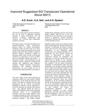
AND8293/DImplementing an LCD TVPower Supply with theNCP1396A, NCP1605, andNCP1027http://onsemi.comPrepared by Roman StulerIntroductionTimer Based Fault ProtectionThis document provides a detailed description of theimplementation of an LCD TV power supply. The LDC TVsupply unit exhibits high efficiency, low EMI noise and a lowprofile construction. The board contains DCM/CCM PFCfront stage, 210 W LLC power stage and 12.5 W standbyflyback converter.The design requirements for our LCD TV power unit areas follows:The converter stops operation after a programmed delaywhen the protection is activated. This protection can beimplemented as a cumulative or integrating characteristic.Thus, under transient load conditions the converter outputwill not be turned off, unless the extreme load conditionexceeds the timeout.MinMaxUnitInput VoltageRequirement90265VacOutput Voltage 1-12VdcOutput Current 103AOutput Voltage 2-24VdcOutput Current 206AOutput Voltage 3-30VdcOutput Current 301AOutput Voltage Standby Output-5VdcOutput Current Standby Output02.5ATotal Output Power0222.5WTotal No Load Consumption for0.5W Load on the Standby Output-1WNOTE:Common Collector Optocoupler ConnectionThe open collector output allows multiple inputs on thefeedback pin i.e. over current sensing circuit, overtemperature sensor, etc. The additional input can pull up thefeedback voltage level and take over the voltage feedbackloop.600 V High Voltage Floating DriverThe high side driver features a traditional bootstrapcircuitry, requiring an external high-voltage diode for thecapacitor refueling path. The device incorporates an upperUVLO circuitry that guarantees enough Vgs is available forthe upper side MOSFET.Adjustable Dead-Time (DT)Due to a single resistor wired between DT pin and ground,the user has the option to include needed dead- time, helpingto fight cross- conduction between the upper and the lowertransistor.Only 24 V output is regulated in this version of the board.Additional output(s) regulation can be assured by addingfeedback resistors to desired output (or outputs forpercentage weight).Adjustable Minimum and Maximum FrequencyExcursionUsing a single external resistor, the designer can programits lowest frequency point, obtained in lack of feedbackvoltage (during the startup sequence or in short- circuitconditions). Internally trimmed capacitors offer a 3%precision on the selection of the minimum switchingfrequency. The adjustable maximum frequency is less precise( 15%). Please refer to the NCP1396A/B data sheet fordetailed description of all mentioned and additional features.The NCP1396A resonant mode controller has beenselected for this application because the soft- start absence onthe fast fault input offers an easy implementation of the skipcycle mode. This helps to assure regulation of the resonantconverter under no load conditions. The NCP1396A offersmany other features that are advantageous for our application.Brown-Out (BO) Protection InputThe input voltage of the resonant converter, when divideddown, is permanently monitored by the Brownout pin. If thevoltage on the bulk capacitor falls outside of the desiredoperating range, the controller drive output will be shut off.This feature is necessary for an LLC topology that uses PFCstage without PFC OK control output. In our case the BOinput is used as an enabling input and is fully controlled by thefront stage controller output (PFC OK). Semiconductor Components Industries, LLC, 2007June, 2007 - Rev. 1Detailed Demo Board Connection DescriptionA schematic of the proposed LCD TV power supply isshown in Figure 1. As already mentioned, the supply containsthree blocks: a PFC front stage, an LLC converter and anauxiliary flyback converter that powers a TV set duringstandby and provides bias power for PFC and LLC controlcircuits during normal operation.1Publication Order Number:AND8293/D
AND8293/DFigure 1. Schematic of the NCP1396A LCD TV Applicationhttp://onsemi.com2
AND8293/DPFC Front Stagevoltage range is restricted by the Brown Out sensingnetwork R64, R68, R70, R77 and C48. The NCP1027 switcherfeatures adjustable ramp compensation capability - resistorR78. Feedback loop is accomplished in the standard way: theoutput voltage level is regulated by the IC6 to the valuewhich is defined by resistors R74 and R80. Bias current foroptcoupler OK3 and regulator is provided from the standbysupply output using resistors R72 and R73. Resistors R75 andR79 are used to stabilize the maximum output power levelwith bulk voltage evaluation (CS comparator delaycompensation). A standard RCD voltage clamp (R66, R67,C41, D21) is installed on the switcher drain to limit its voltageto safe level. There is an optional layout on the board so theTVS (D19) can be used instead of the RCD clamp. Thissolution further decreases standby power consumption,however, price is slightly higher. Voltage from auxiliarywinding, which is used to power the switcher is also used tofeed up the PFC front stage and the main LLC convertercontrol circuits. This voltage is limited by a simple zenerregulator (D22, Q7, R76 and C46) and can be inhibited by theOK2 action. Standby mode can be activated either bypositive or negative logic signals (Q5 or Q6 assembled).Please refer to the application note AND8241/D for adetailed explanation on how to design a Standby flybackconverter using the NCP1027 switcher.The NCP1605 (IC1) PFC controller is used for PFC frontstage control. This front stage works either in fixedfrequency discontinues mode or critical conduction modedepends on the line and load conditions. Capacitors C42,C30, CY1, CY2 with common mode choke L9, inductors L6,L7 and varistor R28 form the EMI filter, which suppressesnoise conducted to the mains. A bridge rectifier B1 is usedto rectify the input AC line voltage. Capacitor C5 filters thehigh frequency ripple current, which is generated by the PFCoperation. In this application a classical PFC boost topologyis used. The PFC power stage is formed by inductor L2,MOSFET switch Q2, diode D4, bulk capacitors C6, C7 andinrush current bypassing diode D2. The current in the PFCstage is monitored by current sense network R13, R14 andR15. Right input voltage operating range is adjusted by theBrown Out sensing network R2, R5, R10, R16, R36 and C21.Output voltage of the PFC stage is regulated to a nominal395 Vdc via the feedback network R3, R6, R11, R22, R29 andR30. Sensing network described above is also used tomonitor an overvoltage condition on the PFC output usingthe NCP1605 OVP pin. PFC regulation loop bandwidth islimited by the capacitor C22. The sensitivity of the zerocurrent detection circuitry is given by the resistor R39 value.Capacitor C19 and resistor R40 are used to control themaximum Q2 switch on-time. Capacitor C24 dictates theDCM operating frequency. Skip mode of the PFC front stageis initiated by the NCP1605 controller when the voltage onthe STBY pin is lower than 0.3 V. Since the LLC stagevoltage feedback and also bulk capacitor voltage haveopposing reaction function (increasing when output loaddecreases), the divided (R35, R43 and C25) LLC stageprimary current information has been used to trigger thePFC skip mode during light load conditions.The controller receives the VCC voltage from standbystage when standard operation mode is enabled by the TV setapplication.Please refer to the application note AND8281/D for adetailed explanation on how to design a PFC front stageusing the NCP1605 controller.LLC Power StageAs previously mentioned, the NCP1396A (IC3) resonantmode controller is used to control the main SMPS unit. Thepower stage of the LLC converter is formed by bulkcapacitors C6, C7, MOSFETs Q1, Q3, transformer TR1 andresonant capacitor C11. MOSFETs are driven directly by thecontroller. Resistors R19 and R20 damp the gate chargingcircuit to suppress overshoots on the gates and regulate EMInoise. Bootstrap diode D14 is charging the bootstrapcapacitor C28 via resistor R42. The bootstrap capacitorpowers a floating driver when high side MOSFET is turnedon. Safety resistors R4 and R12 are used to protect MOSFETs(during the experiments on the bench, for instance, when IC3is removed).Center-tapped windings on 12 V and 24 V outputsincrease the converter efficiency. A bridge rectifier is usedfor 30 V output. Different shottky diode types (D3 with D5,D6 through D10 and D11) are used for secondary rectificationaccording to output voltage, power losses and also shortcircuit capability (not to damage diode during hard short onthe output). The low ESR, high temperature electrolyticcapacitors C1 through C4, C8 through C10, C12 through C16,together with inductors L1, L4, and L5 serve as filters forcorresponding outputs. The secondary voltage regulator IC2regulates the output voltage to 24 V, which is value adjustedby resistor divider composed by R24, R48 and R49. If needed,there can be optionally used feedback from other secondaryoutput(s) (R26 and R27 are included in the board layout). Onthe primary side, the optocoupler works in the connectionwith a common collector which also allows an easyimplementation of the current regulation loop. MaximumStandby SupplyAn ON Semiconductor NCP1027 monolithic switcher(IC5) is used for auxiliary (or standby) power stage providea cost effective solution, needed output power and lowstandby consumption, since this switcher offers skip modecapability under light load conditions. The nominal outputpower of this converter is 12.5 W. The unit is connecteddirectly to the bulk capacitors so during standby conditionsit operates from rectified mains. During normal operatingconditions the switcher is energized by higher voltage (PFCfront stage is working). After the start (that is assured byinternal current supply) the switcher is powered from theauxiliary winding. Diode D23 is used for rectification andcapacitor C47 to filter auxiliary voltage. Resistor R71 limitsthe ICC current so the auto-recovery OVP is not activated forthe correct VCC voltage. The appropriate operating bulkhttp://onsemi.com3
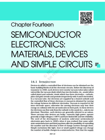
AND8293/Dconverters, offers extra high leakage inductance valuethanks to a special windings arrangement (see demo boardphoto in Figure 24). The leakage inductance serves as aresonant inductance, which results in a cost effectivesolution since no additional inductor is needed to form aresonant tank. Specified parameters of the mentionedtransformer are as follows:current through the optocoupler transistor is adjusted by aresistor R33. To speed up the regulation response, resistorR47 is connected to the feedback pin.Capacitor C34 defines the soft start length. Note that thecurrent regulation loop is used in this power stage so it takescontrol during the startup and affects the soft start action.Resistors R53, R55 and R57 define maximum operatingfrequency, minimum operating frequency and dead time.The operation/fault time period during the overload isdictated by C35 and R54 values.The LLC power stage operation is conditioned to thecorrect PFC front stage operation indicated by the PFC OKsignal. This signal, divided down by resistors R32 and R56,enables the NCP1396A controller when the bulk voltage isin the right range (PFC stage reached regulation).Resistor divider R51 and R58 with bypass capacitor C37are used to prepare skip mode during light or no loadconditions on the power stage output. This skip mode limitsthe maximum needed operating frequency of the converterand improves no load efficiency of the LLC stage.As already mentioned, the current feedback loop is usedin this design. It limits the primary current of the power stageduring overload and helps to implement hick-up mode.Primary current is sensed using charge pump R17, C18, D12,D13. Output of this charge pump is divided and filtered byR31, R18 and C17. Maximum value of this voltage (and thusalso the primary current) is regulated to 1.24 V by IC4regulator. The compensation of current regulation loop isaccomplished by C31 capacitor. Zener diode D15 is used tolower maximum voltage on IC4. Since we need to bring upthe NCP1396 feedback pin to increase the operatingfrequency during overload, transistor Q4 with resistors R38and R44 are used to perform inversion. Output voltage on theQ4 collector is limited by zener diode D18 to 7.5 Vmaximally. This voltage divided down by resistors R52 andR59 triggers the slow fault input in case of an overload andalso drives the NCP1396A feedback pin via diode D17. Thisdiode assures that the slow fault input is not triggered duringlight load conditions and in skip mode when the IC3feedback pin voltage is pushed up by the voltage feedbackloop.Controller IC3 receives the VCC voltage from standbystage during normal operation mode. Auxiliary winding ofthe resonant transformer W7 (when half wave rectified byD1) helps to power the control circuits when load on thestandby supply output is too low and there is a lack of voltageon the standby auxiliary winding due to pure flybacktransformer coupling. Please note that all outputs of theconverter (including standby stage) are referenced to onesecondary ground (S GND).Leakage (Resonant) InductancMagnetizing InductancePrimary Turns Count24 V Output Turns Count12 V Output Turns Count30 V Output Turns CountAuxiliary Winding Turns CountLm/Ls RatioLs 115 mHLm 450 mH384253450/115 3.9Low value of the Lm/Ls ratio together with high turnsratio of the transformer will result in the high gain values.Note that the manufacturer specifies the LS inductance ina standard way - all secondary windings are shorted duringthe Ls measurements. This approach is OK for a transformerthat has one secondary winding, but in our case we havethree different secondary windings and two of them arecenter taped so only one of the corresponding windingparticipates on the resonance during one half of theswitching period. As a result, the real leakage inductancethat participates on the resonance is higher. Due to this fact,the simulation results of gain characteristics that areaccomplished based on the transformer datasheet values, arenot accurate enough to determine operating frequency rangeof the proposed converter.The most accurate method how to obtain gaincharacteristics of the LLC converter that uses integratedtransformer solution with multiple outputs, is to use again-phase analyzer. To do so it is necessary to loadmeasured transformer outputs by equivalent AC resistancesbefore measurements (first fundamental approximation see [5] and [6]). For the center taped windings connect theAC resistance only to one of the windings of the pair - thiswill happen in reality - only one diode conducts the currentduring one half of the switching period. The AC resistancefor corresponding output can be calculated usingEquation 1.R ac 8 V out ) V fp2(eq. 1)I outWhere:Voutis the DC output voltage for given outputVfis the rectifier forward voltageIoutis the DC output current from given outputThe output current has to be selected based on what typeof gain characteristics one wants to obtain - full load, 10%load etc. Connection of the transformer during the gaincharacteristics measurements can be seen in Figure 2.LLC Transformer and Resonant TankA transformer from the standard production of the Pulseengineering company has been used for this design. Thistransformer, which is specially designed for LLChttp://onsemi.com4
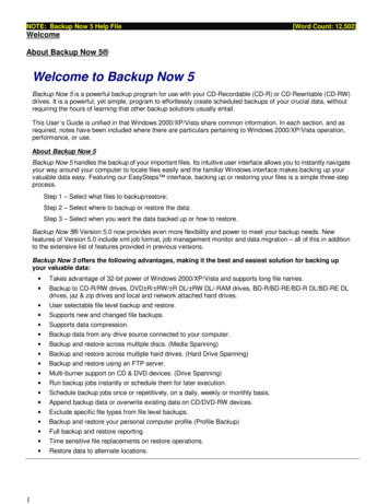
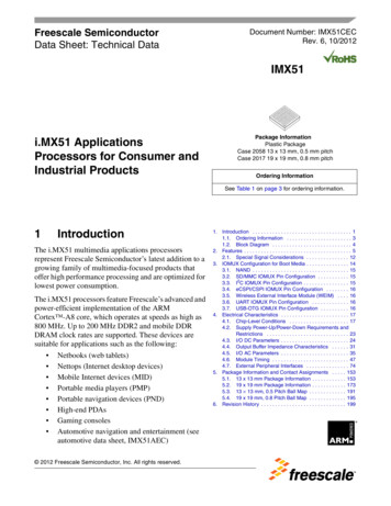
AND8293/D The minimum needed operating frequency to assurelow line regulation is 79 kHz The maximum needed operating frequency to assurehigh line regulation is 106 kHz The converter will operate in the calculated seriesresonant frequency for Vbulk 360 VDCAs demonstrated, the converter will operate above thecalculated theoretical series resonant frequency for nominalbulk voltage and full load. The ZCS capability is thus notachieved on the secondary diodes. Also the neededoperating frequency range of this converter is very narrow,which is beneficial for LCD TV application - EMI radiationand filtering.Gain characteristic of this converter for Iload 0.10 * Imaxand same parameters as above is in Figure 4.0.210.19Figure 2. Transformer Connection During GainCharacteristics MeasurementsGAIN (-)0.17The resonant tank quality factor of Q 4.3 (thatcorresponds to resonant capacitor Cr 33 nF) has beenselected for this design in order to narrow operatingfrequency range of the converter.The measured full load gain characteristic for the selectedresonant tank components and 24 V output can be observedin Figure 3.The gains that are needed to assure line regulation can becalculated using Equations 2 through 4:G nom G max V inmax2ǒV out ) V fǓV innom2ǒV out ) V fǓV inmax 2(24 ) 0.6)4252(24 ) 0.6)395 0.116(eq. 2) 0.125(eq. 3) Gmax0.1250.11Gmin0.070.052.0E 046.0E 041.0E 051.4E 051.8E 05FREQUENCY (Hz)Figure 3. FLLC Converter Gain Characteristicfor Full Load and Q 4.3 (Cr 33 nF)21.81.6 2(24 ) 0.6)3501.4 0.141(eq. 4)Theoretical series resonant frequency can also becalculated based on the Equation 5:f r1 0.13Operating Point forVbulk 395 V andFull Load0.09GAIN (-)G min 2ǒV out ) V fǓ0.151.210.810.62 @ p @ ǸL r @ C r0.4(eq. 5)12 @ 3.14 @ Ǹ115 @ 10 - 6 @ 33 @ 10 - 90.2 81.7 kHz0.12502.E 04Now, when looking back to the gain characteristic inFigure 3, the operating conditions of the full loaded LLCpower stage can be read: The nominal operating frequency of such converter is94.6 kHz (for nominal bulk voltage)6.E 04Operating Point forVbulk 395 V andFull Load100kHz1.E 051.E 052.E 05FREQUENCY (Hz)Figure 4. LLC Converter gain Characteristicfor 10 % Load Conditionshttp://onsemi.com5
AND8293/DThis characteristic shows that the operating frequency hasto be increased above 100 kHz to maintain regulation underlight load conditions. Skip mode for the LLC stage can thusbe easily implemented when maximum frequency is limitedby Fmax adjust resistor value.Please refer to the application notes AND8255/D andAND8257/D for further information about the LLCconverter resonant tank components design.Standby (PFC and LLC disabled) consumptioncharacteristic with line voltage for 0.5 W load on the standbyoutput is in Figure 7. The consumption is below 1 W for anyinput voltage so today's energy agency's needs are easilymet thanks to this design.950900Results SummarizationPIN (mW)Operating frequency of real LLC stage is 96.1 kHz for fullload and Vbulk 395 VDC, which is very close to thetheoretical expectations. Output current level during whichthe skip mode takes place (LLC stage) has been setapproximately to 8 W by R50, R57 divider. The PFC stageenters skip mode for output power lower than 25 W andleaves it for Pout 30 W.Measured efficiency for different input voltages and loadconditions can be seen in Figures 5 and 6.850800750700850.92EFFICIENCY (-)EM 2300.88EM 1100.860.840.820.8406080100 120 140 160 180 200 220TOTAL OUTPUT POWER (W)Figure 5. Total Efficiency versus Output Power andLine0.915FULL LOAD EFFICIENCY 690110130125145165 185 205VIN (VAC)225245265Figure 7. Standby Consumption versus Line Voltage- 0.5 W Load on STB Output0.90.7820105150 170 190 210INPUT VOLTAGE (VAC)230250Figure 6. Total Full Load Efficiency versus InputVoltagehttp://onsemi.com6
AND8293/DFigure 8. LLC Converter Waveforms During SkipMode (1 - Bridge Voltage, 2 - Output Ripple on12 V Output, 3 - Feedback Pin of the NCP1396)Figure 9. Output Ripple on Each LLC StageOutput for Full Load Conditions (1 - 24 V Output,2 - 30 V Output, 3 - 12 V Output)Figure 10. LLC Stage Load Regulation for 230 VInput Voltage (2 - Output Voltage on the 24 V Output,4 - Output Current from the 24 V Output)Figure 11. LLC Stage Operating Under ShortCircuit (1 - Ctimer Voltage, 2 - Feedback Voltage,4 - Primary Current)Figure 12. LLC Stage Full Load Operation(1 - Bridge Voltage, 4 - Primary Current)Figure 13. Detail of the ZVS Condition on theBridge - Rising Edge (1 - Bridge Voltage,4 - Primary Current)http://onsemi.com7
AND8293/DFigure 14. Detail of the ZVS Condition on theBridge - Falling Edge (1 - Bridge Voltage,4 - Primary Current)Figure 15. Standby Power Supply Waveforms Full Loaded (1 - NCP1027 Drain Voltage,4 - Drain Current)Figure 16. Standby Power Supply Waveforms No Load Conditions (1 - NCP1027 Drain Voltage)Figure 17. PFC Stage Skip Mode(1 - Q2 Drain Voltage, 2 - Bulk Voltage)Layout Consideration6. Application note AND8257/D7. Application note AND8281/D8. Bo Yang - Topology Investigation for Front EndDC-DC Power Conversion for Distributed PowerSystem9. M. B. Borage, S. R. Tiwari and S. Kotaiah Design Optimization for an LCL - Type SeriesResonant Converter10. Pulse Engineering - Transformer specification,No: 2652.0017A11. Pulse Engineering - Transformer specification,No: 2362.0031B12. Pulse Engineering - PFC inductor specification,No: 2702.0012APlease contact Pulse Engineering Company regardingliterature 10 - 12:Pulse European HeadquartersEinsteinstrasse 171083 HerrenbergGermanyTEL: 49 7032 7806 0FAX: 49 7032 7806 12Leakage inductance on the primary side is not very criticalfor the LLC converter compared to other topologies, becauseit will only slightly modify the resonant frequency. Howeverit is well to keep the areas of each power loop as small aspossible due to radiated EMI noise. A two- sided PCB withone side ground plane helps (see Figures 21 and 23).ThanksI would like to thank the PULSE engineering company forprovided samples and support for magnetic componentsused in this board.I would also like to thank the COILCRAFT company forproviding samples of the filtering inductors.CAUTIONThis demo board is intended for demonstration andevaluation purposes only and not for the end customer.Literature1. NCP1396A/B data sheet2. NCP1605 data sheet3. NCP1027 data sheet4. Application note AND8241/D5. Application note AND8255/Dhttp://onsemi.com8
AND8293/DEN50081-1 (Domestic) Conducted EmissionsEN50081-1 (Domestic) Conducted Emissions90808070706060LEVEL (dBmV)LEVEL 0k1510FREQUENCY (mHz)FREQUENCY (mHz)Figure 18. Conducted EMI Signature of theBoard for Full Load and 230 VAC InputFigure 19. Conducted EMI Signature of theBoard for Full Load and 110 VAC Inputhttp://onsemi.com930
AND8293/DFigure 20. Component Placement on the Top Side (Top View)http://onsemi.com10
AND8293/DFigure 21. Top Side (Top View)http://onsemi.com11
AND8293/DFigure 22. Component Placement on the Bottom Side (Bottom View)http://onsemi.com12
AND8293/DFigure 23. Bottom Side (Bottom View)http://onsemi.com13
AND8293/DFigure 24. Photo of the Designed Prototype (Real Dimensions are 200 x 130 mm)http://onsemi.com14
AND8293/DBILL OF printManufacturerManufacturerPart NumberB11Bridge RectifierKBU8MKBUFairchildKBU8MC1, C2, C3,C8, C9, C12,C13, C14,C15, r220mF/63V10%CPOL-EUE5-10.5Rubycon63 YXA220M 10x16C111MKP 73-0.033 mF 15 -10.5Rubycon35 RX30220M 10x12.5C17, C482CeramicCapacitor PC191CeramicCapacitor SMD8n210%C-EUC1206EpcosB37872A5822K060C20, C23,C32, C33,C36, C526C211CeramicCapacitor Capacitor Capacitor apacitor SMD1n210%C-EUC1206EpcosB37872A5122K060C26, C28,C38, C40,C515CeramicCapacitor Capacitor pacitor apacitor apacitor yticCapacitor4m7/35V20%CPOL-EUE2-5Rubycon35 MH54.7M 4x5C371CeramicCapacitor SMD2n210%C EUC1206EpcosB37872A5222K060Rubycon25 NXA220M 10x12.5NUC-EUC1206C391C4, 5C411MKP ubycon50 MH51M 5-8Rubycon50 PK100M 2.5-6Rubycon50 MH710M 6.3x7C5, C30,C423MKP 6KM410000N1MC501CeramicCapacitor 150-064X183Please see the NCP1396A/B product folder on www.onsemi.com for PCB Gerber files and other collateral informationregarding this demo board.http://onsemi.com15
AND8293/DBILL OF printManufacturerManufacturerPart '22L35'Rubycon450 VXG100M 22L35 90'Rubycon450 VXG100M 22x30CY1, E3KX222MA5BD1, D8, D12,D13, D175DiodeMMSD4148SOD-123ON SemiconductorMMSD4148T1GD111Dual DiodeMBRF20100CTTO-220ON SemiconductorMBRF20100CTGD14, D21,D233DiodeMURA160SMDSMAON SemiconductorMURA160T3GD151Zener Diode3V3SOD-123ON SemiconductorMMSZ3V3T1GD161D181ON SemiconductorMMSZ7V5T1GD191D21D205%NUZener Diode7V5SOD-1235%SOD-123NUSMADiode1N5408Axial Lead9.50x5.30mmON Semiconductor1N5408G1DiodeMBRS340T3SMCON SemiconductorMBRS320T3GD221Zener Diode18VSOD-123ON SemiconductorMMSZ18T1GD3, D5, D6,D7, D9, D106DiodeMBRS4201T3G5%SMCON SemiconductorMBRS4201T3GD41DiodeMSR860TO-220ON SemiconductorMSR860GF11FUSEHOLDER, 20X5MMSH22, 5ASH22, 5AMulticompMCHTC-15M1COVER, PCBFUSEHOLDERMulticompMCHTC-150M1FUSE,MEDIUMDELAY 4A4ABUSSMANNTDC 210-4AHEATSING11HeatsingSK 454 150 SASK454/150 GNDFischer ElektronikSK 454 150 SAHEATSING21HeatsingSK 454 100 SASK454/100 GNDFischer ElektronikSK 454 100 SAIC11PFC ControllerNCP1605SOIC 16ON SemiconductorNCP1605DR2GIC2, IC62ProgrammablePrecisionReferenceTL431SO8SOIC-8ON 1396ASOIC 16ON ReferenceTLV431ASOT-23ON SemiconductorTLV431ASN1T1GIC51HV Switcher forMedium PowerOffline SMPSNCP1027PDIP (8 Minus Pin 6)ON SemiconductorNCP1027P065GJ1, ctorLP7.5/2/903.2 ORWeidmuellerWeidmuellerLP7.5/2/903.2 ORL1, L4, 21Inductor2702.0012A(260mH)15%Pulse 2702Pulse2702.0012AL31L6, L7220%DO5040H 0005APlease see the NCP1396A/B product folder on www.onsemi.com for PCB Gerber files and other collateral informationregarding this demo board.http://onsemi.com16
AND8293/DBILL OF EMI Filter7mHTLBIPulse6001.0069OK1, HCPL-817-300EQ1, 0STMicroelectronicsSTP12NM50FPQ41PNP GeneralPurposeTransistorBC856-16L T1SOT-23ON
Implementing an LCD TV Power Supply with the NCP1396A, NCP1605, and NCP1027 Prepared by Roman Stuler Introduction This document provides a detailed description of the implementation of an LCD TV power supply. The LDC TV supply unit exhibits high efficiency, low EMI noise and a