Transcription
CR SFTY: 99900313: 20180530iOperator’sCrane Safety ManualIOWA MOLD TOOLING CO., INC.BOX 189, 500 HWY 18 WEST, GARNER, IA 50438TEL: 641-923-3711FAX: 641-923-2424MANUAL PART NUMBER 99900313Iowa Mold Tooling Co., Inc. is an Oshkosh Corporation company.
CR SFTY: 99900313:20000705ii
CR SFTY: 99900313:20000705iiINTRODUCTIONThis Crane Safety Manual is intended as a basic source of information on the safe operation of your crane. Itprovides general information as well as specific information on IMT cranes and their operation as concerns safety.It is not intended as an all encompassing “rule-book” on crane safety. IMT presents this information as areference and guide only. It is your responsibility to identify specific safety hazards and determine properprocedures to prevent those hazards from inflicting injury.We at IMT believe that safety is paramount in the operation of its equipment. Please furnish a copy of thismanual to all persons involved in the operation and maintenance of your IMT crane. IMT grants you, thepurchaser, the right to reproduce this document for that purpose and to further the education in safe operation andmaintenance.Copies of this manual are also available from IMT and its distributors at a nominal price. Please contact yourdistributor or IMT for additional copies.NOTICE TO THE OWNER / USERIf your crane is involved in a property damage accident, contact your IMT distributor immediatelyand provide them with the details of the accident and the serial number of the crane. If anaccident involves personal injury, immediately notify your distributor and IMT’s Safety Directorat:IOWA MOLD TOOLING CO., INC.500 HWY 18 WEST, GARNER, IA 50438641 - 923 - 3711REVISIONS 12091420140915LOCATION12-121-11-18-59-5 THRU 8THROUGHOUT9-5 AND 63-123-14DESCRIPTION OF CHANGECORRECTED MISSPELLINGUPDATE WITH NEW OWNER STATEMENT.UPDATED OSHKOSH STATEMENT.ADDED WIRE ROPE LAY INFORMATIONADDED STABILITY TESTECN 11628 - UPDATED STABILIZER WORDING, SAFETY DECALS.ECN 11606 - ADDED OVERLOAD PROTECTION INFORMATION, ARTICULATED CRANE TWO-BLOCKPREVENTION DEVICE.EDITED STABILITY TESTECN 12264 - MOLUB-ALLOY 882 WAS MOLUB-ALLOY 936, UPDATED DECALECN 12279 - REMOVED MOBIL OIL INFO FROM 70394189
CR SFTY: 99900313:19990512iiiTABLE OF CONTENTSSection 1. GENERAL INFORMATIONGeneralCrane Safety Manual1-11-2Section 2. CRANE COMPONENTIDENTIFICATIONComponent Identification2-1Section 3. DECALSDecal Placement - Telescoping CranesDecal Placement - Articulating Cranes"Danger” Decal DescriptionsInstructional Decals3-13-23-33-10Section 4. HAND SIGNALSSignals4-1Section 5. THE OPERATOROperator QualificationsPhysical ConditionOperator ConductKnowledge And Abilities Required5-15-15-15-2Section 6. CRANE OPERATIONOperation ResponsibilitiesInspectionsCrane TransportCrane Set-UpSafe Crane OperationCrane CapacityCrane ControlsOperating The CraneMaintenanceImportant PrecautionsFire PrecautionsWinch Related PrecautionsEngaging The PTODisengaging The on 7. CRANE OPERATIONNEAR POWERLINESPrecautionsIf Electrical Contact Occurs7-17-2Section 8. WIRE ROPE PRECAUTIONSGeneralWire Rope DescriptionBasic InformationWire Rope InspectionWire Rope PrecautionsLubrication Of Wire RopeWhen To Replace Wire RopeWire Rope SlingsBasic HitchesSling LoadingWire Rope LayWedge Socket AttachmentCable Thimble ection 8A. HOOK PRECAUTIONSGeneralLatchesHook SwivelsHook PrecautionsHook InspectionNew and Repaired HooksHooks in Regular UseHooks Not in Regular UseMethods of Hook InspectionHook Inspection ChecklistHook TestingDefinitionsSection 9. CAPACITY PLACARDSCrane Capacity PlacardsCapacity ConditionsUsing The Capacity Placard(Articulating Cranes)Using The Capacity Placard(Telescoping Cranes)Crane A-48A-59-19-19-19-29-5Section 9A. OVERLOAD PROTECTION SYSTEMSCrane Overload Protection System9A-1Overload Protection System(Hydraulically Operated)9A-2Overload Protection System(Electrically Operated)9A-2Section 10. OPERATIONAL REFERENCEExtension Boom SequenceAnti Two-Blocking DeviceFigure-Four Folding CranesStowing Telescoping CranesStowing Articulating CranesStabilizer OperationDirection TerminologyCrane n 11. MAINTENANCE PRECAUTIONSMaintenance Precautions11-1General Precautions11-1Chemicals11-2Section 12. REFERENCE DATATurntable Bearing FastenerTightening Sequence12-1Tire Inflation Pressures - Bias Ply12-2Tire Inflation Pressures - Radial Ply12-3Tire Inflation Pressures - Wide Base & Low Profile 12-4Tire Inflation Pressures - Imported12-5Torque Data Chart12-6Crane Inspection Checklist12-7
CR SFTY: 99900313:19990512ivLIST OF r ClearanceTypical Page DescriptionRevised PageTelescoping Crane - Major AssembliesTelescoping Crane - Hydraulic ComponentsArticulating Crane - Major AssembliesArticulating Crane - Hydraulic ComponentsTypical Gear Train ConfigurationDecal Locations On Telescoping CranesDecal Locations On Articulating CranesDecal - Electrocution HazardDecal - Electrocution HazardDecal - Electrocution HazardDecal - Electrocution HazardDecal - Electrocution Hazard-RC OperDecal - Electrocution Hazard-RC OperDecal - Electrocution Hazard-RC OperDecal - Electrocution Hazard-RC OperDecal - Stabilizer Foot Crushing 2.F-3.Decal - Moving Boom HazardDecal - Moving Driveline HazardDecal - Two Block HazardDecal - Riding on Boom HazardDecal - Hoisting Personnel HazardDecal - Untrained Operator HazardDecal - Multiple Operation HazardDecal - Failure to Obey HazardDecal - Failure to Obey HazardDecal - Free Falling Manual Boom HazardDecal - Warning Manual StabilizersDecal - Set Up / Stow InstructionsDecal - Rotational AlignmentDecal - Grease WeeklyDecal - Rotate Crane / GreaseDecal - Contact IMTDecal - Return LineDecal- Suction LineDecal - Lubricate Worm GearDecal - Caution Do Not Wash / WaxDecal - Boom Angle IndicatorDecal - Caution Oil LevelDecal - Hyd Oil Fill RecommendationsCrane Operation Hand SignalsOperator QualificationsPhysical ConsiderationsSafety Is Your ResponsibilityCrane Set-Up PrecautionsDo Not Ride The LoadlinePTO Danger -2.Electrical Hazard Warning DecalRequired Clearances Of CranesFrom Electrical Transmission LinesDanger Zone For Cranes OperatingNear Electrical Transmission LinesWhen To Replace Wire RopeBasic HitchesLoad at Various Sling AnglesApproved Wedge Socket Attachment MethodsApproved Cable Thimble Attachment MethodCommon HooksHook TerminologyOne-Part Line ConfigurationTwo-Part Line ConfigurationThree-Part Line ConfigurationArticulating Crane Capacity Placard DescriptionTelescoping Crane Capacity Placard DescriptionStability ChartProper Extension Boom DeploymentImproper Extension Boom DeploymentTwo-Blocking DecalAnti Two-Blocking Device ComponentsNormal Work PositionApproaching Two-Blocking SituationStow / Unfold DecalUnfolding SequenceFolding SequenceTelescoping Crane Stowage ConfigurationArticulating Crane StowageConfiguration - Boom SupportArticulating Crane StowageConfiguration - Retracted Outer BoomStabilizer Deployment SequenceMoving Stabilizer DecalStand Clear DecalStabilizer Storage SequenceCrane Operation Directional TerminologyGrease Weekly DecalLubrication Product and ScheduleTypical Grease Zerk Locations Telescoping CranesTypical Grease Zerk Locations Articulating CranesChemical Container LabelTurntable Bearing Fastener Tightening SequenceTire Load And Inflation Pressures - Bias PlyTire Load And Inflation Pressures - Radial PlyTire Load And Inflation Pressures Wide Base & Low Profile Radial PlyTire Load And Inflation Pressures Imported Radial PlyRecommended Bolt 112-212-312-412-512-6
CR SFTY: 99900313: 199810121-1Section 1. GENERAL INFORMATIONGENERALThe information contained in this Safety Manual isto help provide you with the knowledge necessary inthe safe and proper operation of your crane. Thisinformation is not intended to replace anygovernmental regulations, safety codes orrequirements of insurance carriers. Operators,maintenance and test personnel must read andunderstand all safety procedures applicable to theequipment in use.WARNINGFAILURE TO READ, UNDERSTAND AND FOLLOWANY SAFETY PROCEDURES APPLICABLE TO YOUREQUIPMENT MAY RESULT IN EQUIPMENT DAMAGE,SERIOUS INJURY OR DEATH.Familiarization with this Safety Manual, governmentregulations, hazards and the specific operations ofyour crane is a necessity. The operation andmaintenance of your crane must be done withcaution, while following all safety procedures andapplicable regulations. Common sense is essentialto a safe work environment.Modifications to your crane must be performed withIMT approved accessories, parts and optionalequipment. If in doubt about the safety,compatibility or appropriateness of anymodifications, contact IMT before thosemodifications are made. DO NOT make anyalterations or modifications to any safety device,whether electrical, hydraulic or mechanical innature. All safety devices must be inspected, testedand maintained in proper working condition.Decals instructing the safe use and operation of yourcrane are considered safety equipment and must bemaintained as would any other safety device. Decalsmust be kept clean and legible to the operator,operational personnel and by-standers as specified inthe decal section of this manual. DO NOT remove,disable or disregard any safety device attached toyour crane.The owner and/or designated employee isresponsible to inform all operators, maintenancepersonnel and others involved in the operation ofyour equipment, in the safe operation andmaintenance of your equipment.If any questions concerning safe operation ormaintenance arise, please contact IMT or your IMTdistributor for clarification.WARNINGCHILDREN, BY-STANDERS AND PERSONS NOTREQUIRED IN THE OPERATION OF EQUIPMENTMUST BE KEPT AT A SAFE DISTANCE FROM THATEQUIPMENT. A DISTANCE OF 10'-0” (3.05m) FROMTHE OUTERMOST RANGE OF THE CRANE AND ITSLOAD IS AN ABSOLUTE MINIMUM.Much of the material contained in this manual isspecific to IMT cranes. Much of the general cranesafety information is as presented by The AmericanSociety of Mechanical Engineers' lastest revisions ofMobile and Locomotive Cranes (ASME/ANSI B30.5)and Articulating Boom Cranes (ASME/ANSI B30.22),industry safety standards. These publications areavailable from The American Society of MechanicalEngineers, 345 East 47th St., New York, NY 10017.Crane operators must be familiar with OSHA 29CFR,Subpart N, Article 1926.550 and CAL-OSHA Title 8,Article 93 (California).Figure A-1. By-Stander Clearance
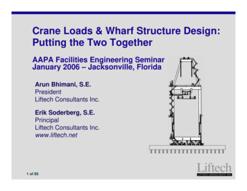
CR SFTY: 99900313: 19981012CRANE SAFETY MANUALThis manual is divided into specific sections in orderto keep similar subject matter under one heading.There will however be instances when a particularsubject may be presented in more than one sectionof the manual. This redundancy is necessary inproviding comprehensive information.This manual will also be subject to revisions andadditions. As new or revised information isreleased, new pages will be available which will beidentified in the upper-right-hand corner by arevision number and date. Any new pages releasedshould be inserted into your manual in place of "oldpages". See Figure A-2 and A-3 for pageinformation.1-2Three means are used throughout this manual to gainyour attention. They are NOTEs, CAUTIONs andWARNINGs and are defined as followsNOTEA NOTE IS USED TO EITHER CONVEY ADDITIONALINFORMATION OR TO PROVIDE FURTHEREMPHASIS FOR A PREVIOUS POINT.CAUTIONA CAUTION IS USED WHEN THERE IS THE STRONGPOSSIBILITY OF DAMAGE TO THE EQUIPMENT ORPREMATURE EQUIPMENT FAILURE.WARNINGA WARNING IS USED WHEN THERE IS THEPOTENTIAL FOR PERSONAL INJURY OR DEATH.New sections may also be provided. When received,they should be inserted into your manual in itsproper numerical sequence.Figure A-2. Typical Page DescriptionFigure A-3. Revised Page
CR SFTY: 99900313: 199810122-1Section 2. CRANE COMPONENT IDENTIFICATIONCOMPONENT IDENTIFICATIONKnow the components of your crane. Doing so willaid in the communication of problems tomaintenance personnel as well as provide immediatereference during an emergency situation.Refer to the illustrations provided in this section.Determine the type of crane specific to youroperation and study the illustrations of mainassemblies and hydraulic components. Thisreference is to IMT cranes specifically and shouldnot be considered universal. There are variancesbetween different crane models and the illustrationsshould be used as reference and compared to theactual equipment in use.NOTE 1.THERE MAY BE MORE THAN ONE EXTENSIONBOOM AND THEY WILL BE IN NUMERICAL ORDERSUCH AS 2ND STAGE OR 3RD STAGE EXTENSIONBOOMS.Figure B-1. Telescoping Crane - Major AssembliesNOTE 1.ROTATION SYSTEMS WILL VARY DEPENDING ONTHE CRANE MODEL. WORM GEAR SYSTEM ISSHOWN.NOTE 2.EXTENSION BOOM CYLINDERS MAY BEINTERNALLY MOUNTED OR EXTERNALLYMOUNTED, DEPENDING ON THE CRANE MODEL.Figure B-2. Telescoping Crane - Hydraulic Components
CR SFTY: 99900313: 201112302-2NOTE 1.STABILIZER DESIGN MAY VARY DEPENDING ON THECRANE MODEL.NOTE 2.EXTENSION BOOMS MAY NUMBER MORE THAN 3AND WILL BE IN NUMERICAL ORDER SUCH AS 4TH,5TH AND 6TH STAGE EXTENSION ILIZERFigure B-3. Articulating Crane - Major AssembliesNOTE 1.CYLINDER MAY BE INTERNALLY OR EXTERNALLYMOUNTED DEPENDING ON THE CRANE MODEL.NOTE 2.“FIGURE-4 FOLDING” ARTICULATING CRANESUTILIZE TWO INNER BOOM CYLINDERS WHILEMOST ARTICULATING CRANES USE ONE INNERBOOM CYLINDER.NOTE 3.HYDRAULIC CONTROLS ARE NORMALLY PRESENTON BOTH SIDES OF CRANE BASE. REMOTECONTROLS MAY ALSO BE USED.POWER OUT STABILIZER CYLINDER(SEE NOTE 1)POWER DOWN STABILIZER CYLINDERFigure B-4. Articulating Crane - Hydraulic Components
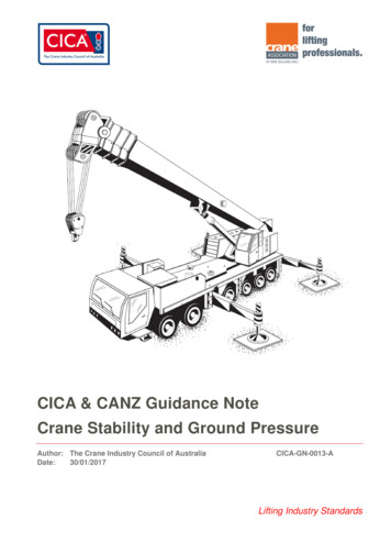
CR SFTY: 99900313: IPTIONROTATION MOTORHYDRAULIC BRAKEDRIVE GEARUPPER DRIVE GEAR BUSHINGLOWER DRIVE GEAR BUSHINGDRIVE GEAR GREASE PLATEINTERMEDIATE GEARPINION GEARUPPER PINION GEAR BUSHINGLOWER PINION GEAR BUSHINGINTERMEDIATE GEAR THRUST BEARINGTURNTABLE GEAR BEARINGFigure B-5. Typical Gear Train Configuration
CR SFTY: 99900313: 199810122-4
CR SFTY: 99900313:201112233-1SECTION 3. DECALSDECAL PLACEMENT-TELESCOPINGCRANESThe positioning of decals on a telescoping crane isusually similar between varying models. Figure C-1illustrates common positioning of decals used ontelescoping cranes.ITEM DECAL DESCRIPTIONQTY SEE -MANUAL STABGREASE WEEKLY-LEFT ARROWGREASE WEEKLY-RIGHT ARROWSUCTION LINERETURN LINECAUTION-DO NOT WASH/WAXROTATE CRANE/GREASECRANE MODEL NUMBERDANGER-ELECTROCUTIONWARNING-UNTRAINED OPERDANGER-OPERATIONWARNING-TWO BLOCKINGWARNING-HOIST PERSONNELWARNING-STAB STAND CLRDANGER-ELECTROCUTIONWARNING-OPER 5.26.27.28.29.30.31.32.WARN-CRANE LDLINE (TRUCK)IMT DIAMONDWARNING-OPERN RESTRICTDANGER-RC ELECTRO-LGDANGER-ROTATING DRIVELINECONTACT IMTCAUTION-OIL LEVELANGLE CHART- RIGHT SIDEANGLE CHART-LEFT SIDECAPACITY CHARTLUBRICATE WORM GEARDANGER-RC ELECTRO-HANDLEWARNING-FALL MNL BOOMHYD OIL RECOMMENDATIONSTABILIZER-FULLY A1-35A1-36NOTEPLACEMENT OF A HAZARD WARNING DECALMUST BE IN A POSITION WHICH IS EASILYVISIBLE TO THE PERSON RESPONSIBLE FORTAKING THE APPROPRIATE ACTION WHICH THATDECAL ADDRESSES.ITEM NUMBERLOCATION6,9,10,11,12,13,1 AT OR NEAR REMOTE CONTROL6, 20, 21, 23, 24, HANDLE STORAGE POINT271,14ONE ON EACH STABILIZER15,187ONE ON EACH SIDE OF THE CARRIERVEHICLEAT TURNTABLE GREASE ZERK2,3AT ALL GREASE ZERKS5ON RESERVOIR AT RETURN LINE4ON RESERVOIR AT SUCTION LINE29ON REMOTE CONTROL HANDLE3031AT OR NEAR MANUAL EXTENSIONBOOM RETENTION MECHANISMON OR NEAR HYD OIL RESERVOIR22AT OR NEAR DRIVELINE28ON WORM GEAR COVER32ON EACH STABIILZER ARM AT FULLEXTENSIONFIGURE C-1. DECAL LOCATIONS ON TELESCOPING CRANES
CR SFTY: 99900313:201112233-2DECAL PLACEMENT -ARTICULATINGCRANESThe positioning of decals on an articulating crane isusually similar between varying models. Figure A1-2illustrates common positioning of decals used onarticulating cranes using remote controls. Decalsspecific to remote controls will not be used onmanually controlled cranes.ITEM DECAL .35.QTY SEE FIG.IMT DIAMOND2SET UP/STOW INSTRUCTIONS 1GREASE WEEKLY-LEFT ARROW ARGREASE WEEKLY-RIGHT ARROWARSUCTION LINE1RETURN LINE1CRANE MODEL NUMBER2CAUTION-DO NOT WASH/WAX 1ROTATE D OPER2WARNINGOPERATION2WARNING-STAB STAND CLEAR 2DANGER-ELECTROCUTION4WARNING-OPER CONDITIONS 2WARNINGOPER RESTRICTIONS 2DANGER-STOW/UNFOLDING2DANGER-ROTATING DRIVELINE 1CONTACT IMT1CAUTION-OIL LEVEL2CAPACITY CHART2STREET SIDE CONTROLS1CURB SIDE CONTROLS1STABILIZER CONTROLS SS1STABILIZER CONTROLS CS1CRANE ROTATION ALIGNMENT 1DANGER-RC ELECTRO-LG2DANGER-RC ELECTRO-HNDL 1WARNING-TWO BLOCKING2WARN-CRANE -LINE (TRUCK)4WARNING-HOISTING PERSON 2WARNING-FREEFALL MNL BOOM 1HYD OIL RECOMMENDATION1STABILIZER-FULLY DEPLOYED 2NOTEPLACEMENT OF A HAZARD WARNING DECALMUST BE IN A POSITION WHICH IS EASILYVISIBLE TO THE PERSON RESPONSIBLE FORTAKING THE APPROPRIATE ACTION WHICH THATDECAL -25A1-7A1-9A1-151-16A1-17A1-22A1-35A1-36IT EM NUM BERL OC A T ION2,8,10,11,12,15,17, 18, 20, 2128, 30, 31, 3213A T OR NEA R THE NORMA LOPERA TING STA TIONS14,319ONE ON EA CH SIDE OF THE CA RRIERV EHICLEA T TURNTA BLE GREA SE Z ERK3,4A T A LL GREA SE Z ERKS6ON RESERV OIR A T RETURN LINE5ON RESERV OIR A T SUCTION LINE29ON REMOTE CONTROL HA NDLE3334A T OR NEA R MA NUA L EXTENSIONBOOM RETENTION MECHA NISMON OR NEA R HY D OIL RESERV OIR19A T OR NEA R DRIV ELINE27A LIGNED ON MA ST A ND BA SE35ON EA CH STA BIILZ ER A RM A T FULLEXTENSIONONE ON EA CH STA BILIZ ERFIGURE C-2. DECAL LOCATIONS ON ARTICULATING CRANES
CR SFTY: 99900313:201112233-3“DANGER” DECAL DESCRIPTIONSAll operators must familiarize themselves with the“DANGER” decals shown in this section. Yourequipment may have additional safety decals that arenot described here. Any safety decals affixed toyour equipment must be identified, read andunderstood.The materials and adhesives used in the productionof these decals were designed for maximumdurability, adhesion and legibility. Nevertheless, if adecal (including capacity chart) becomes damaged orillegible, replace it at your earliest opportunity. If acrane is repaired or repainted, replace all decalsbefore the crane is put back into service. Individualdecals as well as complete decal kits are availablefrom IMT.Shown in the following figures are the safety decalsused on IMT cranes. They are shown here as an aidin their identification with an explanation of theirpurpose, where they are placed on the crane and thenormal quantity used on each crane. All decals areshown half-size.Figure C-3DECAL: Electrocution HazardPART NUMBER: 70392813FUNCTION: To inform the operator of thehazard associated with contact or proximityto electrical lines, the possibleconsequences should the hazard occur, andhow to avoid the hazard.WHERE USED: Articulating cranesPLACEMENT: At or near the operator’scontrol station(s).QUANTITY: 2DANGERElectrocution HazardCrane is not insulatedNEVER approach or contact power lineswith any part of this equipment or load.Keep 50 feet away from any power line ifvoltage is not known.Keep 20 feet away from any power line350 kilovolts or less.Account for swaying motion of power line,equipment, and load line.Follow OSHA 29CFR 1926.1400.Death or serious injury will result fromapproaching or contacting a power line.70392813Figure C-4DECAL: Electrocution HazardPART NUMBER: 70394444FUNCTION: To inform the operator of thehazard associated with contact or proximityto electrical lines, the possibleconsequences should the hazard occur, andhow to avoid the hazard.WHERE USED: Service body mountedTelescoping Cranes - remote controls.PLACEMENT: At or near the remote controlhandle storage point.QUANTITY: 1DANGERElectrocution HazardCrane is not insulatedNEVER approach or contact power lineswith any part of this equipment or load.Keep 50 feet away from any power line ifvoltage is not known.Keep 20 feet away from any power line350 kilovolts or less.Account for swaying motion of power line,equipment, and load line.Follow OSHA 29CFR 1926.1400.Death or serious injury will result fromapproaching or contacting a power line.70394444
CR SFTY: 99900313:201112233-4DANGERElectrocution HazardNever approach this vehicle or theload if it is near power lines.Death or serious injury will result fromtouching or being near this vehicle if itbecomes charged.70392865Figure C-5DECAL: Electrocution HazardPART NUMBER: 70392865FUNCTION: To inform the operator and otherpersonnel in the work area of the hazard associatedwith contact or proximity to electrical lines, thepossible consequences should the hazard occur, andhow to avoid the hazard.WHERE USED: Articulating cranesPLACEMENT: On all four sides of the carrier vehicle.QUANTITY: 4Figure C-6DECAL: Electrocution HazardPART NUMBER: 70394445FUNCTION: To inform the operator and otherpersonnel in the work area of the hazard associatedwith contact or proximity to electrical lines, thepossible consequences should the hazard occur, andhow to avoid the hazard.WHERE USED: Service body mounted TelescopingCranes - remote controlsPLACEMENT: On all four sides of the carrier vehicle.QUANTITY: 4DANGERElectrocution HazardNever approach this vehicle or theload if it is near power lines.Death or serious injury will result fromtouching or being near this vehicle if itbecomes charged.70394445
CR SFTY: 99900313:Figure C-7201112233-5DANGERDECAL: Electrocution Hazard-RemoteControl OperationPART NUMBER: 70392889Electrocution HazardFUNCTION: To inform the operator andother personnel in the work area of the lackof protection from electrocution afforded bythe remote control handle, the possibleconsequences of the crane becomingelectrically charged, and how to avoid thehazard.Tethered remote control is not insulated.Never allow this vehicle, equipment or load tobecome charged while you are holding thiscontrol.Death or serious injury will result from touchingthis control if this vehicle becomes charged.70392889WHERE USED: Articulating cranes - remotecontrolsPLACEMENT: If crane is equipped withmanual control(s) in addition to remotecontrols, placed at or near the operator’smanual control station(s). If crane isequipped with remote controls only, placedat remote control handle storage point.Figure C-8DECAL: Electrocution Hazard-RemoteControl OperationQUANTITY: 2 or 1 if only with remotecontrols.PART NUMBER: 70394446FUNCTION: To inform the operator andother personnel in the work area of the lackof protection from electrocution afforded bythe remote control handle, the possibleconsequences of the crane becomingelectrically charged, and how to avoid thehazard.DANGERElectrocution HazardTethered remote control is not insulated.Never allow this vehicle, equipment orload to become charged while you areholding this control.Death or serious injury will result fromtouching this control if this vehiclebecomes charged.PLACEMENT: At or near the remote controlhandle storage point.70394446Figure C-9QUANTITY: 1DANGERElectrocution HazardTethered remote control is not insulated.Never allow this vehicle, equipment orload to become charged while you areholding this control.Death or serious injury will result fromtouching this control if this vehiclebecomes charged.70394447DANGERElectrocution HazardWHERE USED: Service body mountedTelescoping Cranes - remote controls70392862Tethered remote control is not insulated.Never allow this vehicle, equipment or loadto become charged while you are holdingholding this control.Death or serious injury will result from touchingthis control if this vehicle becomes charged.Figure C-10DECAL: Electrocution Hazard-Remote ControlOperationDECAL: Electrocution Hazard-Remote ControlOperationPART NUMBER: 70392862PART NUMBER: 70394447FUNCTION: To inform the operator of the lack ofprotection from electrocution afforded by the remotecontrol handle, the possible consequences of thecrane becoming electrically charged, and how toavoid the hazard.FUNCTION: To inform the operator of the lack ofprotection from electrocution afforded by the remotecontrol handle, the possible consequences of thecrane becoming electrically charged, and how toavoid the hazard.WHERE USED: Articulating cranes - RemoteControlsWHERE USED: Service body mounted TelescopingCranes - Remote ControlsPLACEMENT: On the hand held controller.PLACEMENT: On the hand held controller.QUANTITY: 1QUANTITY: 1
CR SFTY: 99900313:201112233-6Figure C-11DECAL: Stabilizer Foot Crushing HazardPART NUMBER: 70392864WARNINGFUNCTION: To inform the operator and otherpersonnel in the work area of the hazard associatedwith the operation of the stabilizers, the possibleconsequences should the hazard occur, and how toavoid the hazard.USED ON: Articulating and Service body mountedTelescoping CranesPLACEMENT: On each stabilizer.QUANTITY: 2Crush HazardBefore extending stabilizers:Look around vehicle.Clear area of all people.Extending stabilizers on peoplemay injure or kill.70392864Figure C-12DECAL: Moving Stabilizer HazardNote- Combined with 70392864effective January 1, 2012.Figure C-13DECAL: Moving Boom HazardPART NUMBER: 70392890FUNCTION: To inform the operator and otherpersonnel in the work area of the hazard associatedwith a moving boom especially while stowing andunfolding the crane, the possible consequencesshould the hazard occur, and how to avoid thehazard.WARNINGPLACEMENT: At or near the operator’s controlstation(s) and/or the boom stow area(s).QUANTITY: 2Crush Hazard70392890USED ON: Articulating CranesBefore operating crane:Look around vehicle.Clear area of all people.Stand on side opposite boom.A moving boom may injure or kill.
CR SFTY: 99900313:201112233-7Figure C-14DECAL: Rotating Driveline HazardDANGERPART NUMBER: 70392891FUNCTION: To inform personnel of the hazardassociated with servicing an operating driveline orPTO, the possible consequences should the hazardoccur, and how to avoid the hazard.USED ON:Articulating and Service body mounted TelescopingCranes that are driven by a PTO/pump system.PLACEMENT: At or near the drive line.QUANTITY: 1Rotating Shaft HazardKeep body, hands, hair,clothes away.Do not work around shaftswith engine on.Rotating parts will injure or kill.70392891Figure C-15DECAL: Two Block HazardPART NUMBER: 70392861FUNCTION: To inform the operator of the hazardassociated with bringing the sheave(s) into contactwith the hook, snatch block or load, the possibleconsequences should the hazard occur, and how toavoid the hazard.WARNINGFalling Load HazardAlways stop operation beforethe block contacts sheave.(Two-blocking)Do not rely on limit switch tostop block.USED ON: Articulating and Service body mountedTelescoping Cranes.PLACEMENT: At or near the operator’s controlstation(s).70392861If block contacts sheave, lowerload by letting out cable andinspect for damage.Falling loads may injure or kill.QUANTITY: 2Figure C-16DECAL: Riding on Boom, Hook, or Loadline HazardPART NUMBER: 70392868FUNCTION: To inform personnel in the work area ofthe possible consequences of riding on the boom,boom hook, the load or winch loadline, and how toavoid the hazard.WARNINGFall HazardNever use crane to hoistpersonnel.USED ON: Articulating and Service body mountedTelescoping Cranes.Never ride on boom, hook,load or any other deviceattached to crane boom orload line.PLACEMENT: On all four sides of the vehicle.QUANTITY: 470392868Riding on boom, hook, orloadline may injure or kill.
CR SFTY: 99900313:201112233-8Figure C-17DECAL: Hoisting Personnel on Boom, Hook, orLoadline HazardPART NUMBER: 70392863WARNINGFUNCTION: To inform the operator of the hazardassociated with lifting personnel with the boom, boomhook, the load or winch loadline, the possibleconsequences of lifting personnel, and how to avoidthe hazard.USED ON: Articulating and Service body mountedTelescoping Cranes.Fall HazardNever use crane to hoistpersonnel.Never ride on boom, hook,load or any other deviceattached to crane boom orload line.Riding on boom, hook, orloadline may injure or kill.70392863PLACEMENT: At or near the operator’s controlstation(s).QUANTITY: 2Figure C-18WARNINGDECAL: Untrained Operator HazardPART NUMBER: 70392814FUNCTION: To inform the operator of the need forproper training, familiarity with safe operatingprocedures, and the possible consequences ofoperation without training.Only trained personnel should operate this equipment.Do not operate or service until you have read andunderstood:Operation and service manuals supplied with thisequipment.USED ON: Articulating and Service body mountedTelescoping Cranes.PLACEMENT: At or near the operator’s controlstation(s).Crane load and work area charts.Safety signs and instructions.Employer work rules and applicable government andOSHA regulations.Ma
May 30, 2018 · This Crane Safety Manual is intended as a basic source of information on the safe operation of your crane. It . If Electrical Contact Occurs 7-2 Section 8. WIRE ROPE PRECAUTIONS General 8-1 . C-22. Decal - Free Falling Manual Boom Hazard Configuration3-9 C-23. Decal