Transcription
SECTION 5STREET LIGHT DESIGNTABLE OF CONTENTSStreet Light Design5-15-25-35-45-55-65-75-8PageSTREET LIGHTS - REQUIRED . 5-1STREET LIGHTS - NOT REQUIRED . 5-1DEVELOPER’S RESPONSIBILITY . 5-1UTILITY COMPANY AUTHORIZATION . 5-1GENERAL PLAN DETAILS . 5-2DESIGN STANDARDS . 5-2STREET LIGHT DESIGN DETAILS . 5-2A.Intersections . 5-2B.Cul-de-Sacs and Stub End Streets . 5-2C.Pedestrian Lanes . 5-2D.Spacing . 5-3E.Street Light Poles . 5-3F.Street Lights on Existing Utility-Owned Poles . 5-3G.Light Emitting Diode Luminaires . 5-3H.Service . 5-4I.Pull Boxes . 5-4J.Conductors . 5-4K.Photo Cell . 5-5L.Conduit . 5-5M.Electrical Equipment and Work . 5-5N.Decorative Street Lights. 5-6MASTER PLANNING . 5-7
SECTION 5STREET LIGHT DESIGN5-1STREET LIGHTS - REQUIRED -- Street lights shall be required for all lots andparcels being developed or constructed upon unless excepted by Section 5-2. Inaddition, street lights may be required for lots and parcels containing existingstructures which are being improved or altered, depending on the nature andextent of the work. Illustrations of street lights generally required are shown onStandard Drawing 5-1.5-2STREET LIGHTS - NOT REQUIRED -- Street lights shall not be required underthe following circumstances:5-3A.Single family residential subdivisions having an average lot street frontageof more than 125 feet will not be required to install a street light systemalong the streets, but shall as a minimum, be required to install streetlights at all intersections, cul-de-sacs, and other locations deemed by theDirector to be essential. (e.g. pedestrian tunnel, pedestrian over-crossing,bridges, curves, etc.)B.For planned developments, residential, commercial, and industrialdevelopments where the internal streets are not offered for dedication, astreet lighting system will not be required for the internal non-dedicatedstreets, but shall be provided by the developer on the external publicstreet frontage.DEVELOPER'S RESPONSIBILITY -- Existing street lights which must berelocated or repositioned as a result of the construction of new streets ordriveways into a development shall be the responsibility of the developer.Where a development abuts a collector street, primary residential street, or minorresidential street where Standard Drawings 5-5D, 5-5E and 5-5F assume thatstreet lights will be installed on alternate sides of the street, and where theproperty on the opposite side of the street has developed without street lights,the Director may require the developer to install additional street lights on thefrontage of the development to maintain proper street light spacing.A new service can with a step-down transformer, required as a result of themodification, replacement or relocation of an existing utility service pedestal shallbe the responsibility of the developer. The developer shall also be responsible toensure that power shall remain to existing street lights during the period of any
such modification, replacement or relocation of an existing utility servicepedestal.It shall be the responsibility of the developer to ensure that the power shallremain to the existing street light system until the new street light system iscompleted and functioning correctly.5-4UTILITY COMPANY AUTHORIZATION – The Sacramento Municipal UtilityDistrict (SMUD) rate tables for street light service have been modified as follows:A.The Customer Owned/District Maintained lighting rate is no longeravailable for new street light installations. This may affect the street lightsystems on private streets and courts.B.New Street Light installations on County maintained roadways may requirethe Developer to install a metered street light electrical service. The useof metered vs flat rate electrical billing shall be determined by theDeveloper’s Engineer in consultation with the utility company prior toimprovement plan submittal.A written notice from the serving utility company, stating that line clearances andservices have been checked and are adequate, shall be submitted to the Directorfor all developments.5-5GENERAL PLAN DETAILS -- The plans shall show and identify all street lights tobe installed, all existing lights in the immediate vicinity of the project, all conduitand conductor runs, service points, trees, and all applicable provisions anddetails specified in these standards.On subdivision plans, the street lights shall be shown separately. In addition tothe above, the following shall be required on the street light portion of subdivisionplans, even though duplications may be involved:-A vicinity map or equivalentUtility poles and public utility easementsNames of adjacent subdivisionsIntersecting property lines of adjacent propertiesA “Symbols” legend conforming to Standard Drawing 5-1A North arrow and appropriate scale (1" 10' to 1" 100’)All existing street lights on both sides of any streets and in the medianAll new tree installations shall be more than 20’ from street lightsAll trees within the vicinity of the conduit runs or proposed street lights
5-6DESIGN STANDARDS -- Street lighting shall be designed in conformance withthese specifications, the current edition of the Sacramento County StandardConstruction Specifications, and the "American National Standard Practice forRoadway Lighting" of the American Standards Institute, except that the averagehorizontal maintained foot candles for the various street classifications shall beas shown on Standard Drawings5-5A through 5-5F. Data and calculations supporting the satisfaction of theabove requirements shall be submitted for review, or the predetermined designstandards included herein shall apply.5-7STREET LIGHT DESIGN DETAILS -- Design details for street lights are asfollows:A.Intersections -- Intersections shall have at least one street light.Intersection street light locations and the number required shall conform toStandard Drawings5-6 through 5-7.B.Cul-de-Sacs and Stub-End Streets-- All cul-de-sacs and stub-end streetsexceeding 130 feet in length, measured from the street light location at theintersection to the right-of-way line at the end of the cul-de-sac or street,shall have a street light within the bulb, or in the case of a stub-end street,at the end of street barricade. The location of the street light within thecul-de-sac bulb shall conform to Standard Drawing 5-7.C.Pedestrian Lanes -- Street lights shall be placed at both ends ofpedestrian lanes.D.Spacing -- Maximum street light spacing, measured along the streetcenterline, shall conform to Standard Drawings 5-5A through 5-5F, excepton arterial and thoroughfare streets with a 1,000-foot or smaller radiushorizontal curve, in which case the maximum spacing is 170 feet. Theactual constructed street type and right-of-way width shall be thecontrolling factor for determination of street light spacing rather than thestreet classifications (arterial, collector, etc.).E.Street Light Poles -- All street light poles shall be galvanized steel, exceptas provided for by Item "F" below. All pole construction and materialsshall conform to the standards outlined in the Standard ConstructionSpecifications, Section 49-2.05, “Standards, Steel Pedestals and Posts”,and the Standard Drawings referenced therein. Poles shall be identifiedon the plans or in the special provisions. Identification of Type A streetlight poles shall be by the“A” series numbering procedure” as shown on Standard Drawing 5-3
The position of the street light poles shall conform to Standard Drawings5-5A through 5-8.F.Street Lights on Existing Utility-Owned Poles -- Where there arepermanent existing (or necessary planned) utility owned poles adjacent tothe roadway, the street lights may be installed upon the utility pole in lieuof the required street light poles. Should the utility pole option be utilized,the following shall apply:1.In the Sacramento Municipal Utility District (SMUD) service area,the developer shall arrange with SMUD to install Utility owned andmaintained street lights on existing utility poles. Proof that SMUDhas agreed to the installation of the lights and the SMUD Ratedesignation shall be submitted to the plan check staff prior toapproval of the plans.2.In the Pacific Gas and Electric Company (PG&E) service area, thedeveloper shall arrange with PG&E to install PG&E owned andmaintained street lights on existing utility poles. Proof that PG&Ehas agreed to the installation of the lights and the PG&E Ratedesignation shall be submitted to the plan check staff prior toapproval of the plans.3.Spacing of lights may be varied to meet locations of existing utilitypoles, but shall not exceed the maximum spacing specified byStandard Drawings 5-5A through 5-5F. Street light mountingheights shall be as shown on Standard Drawings 5-5A through 55F. All luminaires shall have wattages relating to the streetclassification requirements shown on Standard Drawings 5-5Athrough 5-5FG.Light Emitting Diode Luminaires – All new street light installations shallutilize Light Emitting Diode (LED) luminaires. The luminaire wattagesshown on Standard Drawings 5-5A through 5-5F are nominal wattages;system wattages, which include the electronic driver, may be higher. LEDluminaires shall conform to the standards outlined in the StandardConstruction Specifications, Section 49-6.03, Light Emitting Diode (LED)Luminaires.H.Service -- All street light systems shall have underground serviceprovided. Service voltage shall be shown on the plans. Service voltageshall be 120 volts. Service voltage may be 277 volts only when 120 voltservice is not available. Service points shall be provided within a PublicUtility Easement immediately adjacent to the right-of-way, or within theright-of-way, and at a point which is as reasonably near as possible to the
serving utility power source. The service point shall be a pull box which iseasily accessible to the street frontage. Types of service are as follows:1.The Director may approve overhead service in unusual areas whenjustification is given for why service cannot be providedunderground.2.A direct underground service consists of one light being servedfrom a single service point. New lights on developments adjacentto existing development shall connect to the existing service point.The service point shall be a pull box installed by the developer.See Standard Drawing 5-12 for commercial and residentialrequirements, and Standard Drawing 5-13 for installation details.3.Multiple service is two or more lights being served from a singleservice point installed by the developer. The service point shall bea pull box. Multiple systems shall have an above ground serviceenclosure which is normally located adjacent to the service pointand within the Right of Way and/or Public Utility Easement,between the service point and the light system. The serviceenclosure shall conform to Standard Drawing 5-30 through 5-33 asappropriate.4.When five or more lights are connected to a single service point, anabove ground, metered service enclosure shall be installed. Themetered service enclosure shall be located per item No. 3 above.I.Pull Boxes -- All pull boxes, including the size, shall be shown andidentified on the plans. Pull boxes shall be installed at all locations wheremore than two conduit runs intersect, where conduit runs are more than200 feet long, where shown on County Standard Drawings, at criticalangle points, at property lines at the end of the required conduit run to theproperty line (see Section 5-7(L), “Conduit”), behind each light when No. 4AWG. conductors are used, and at such locations ordered by the Director.Normally a No. 3-1/2 pull box will be allowed when three or fewer conduitsof 1-1/2” or smaller size are involved and at the end of the requiredconduit run to the property line (see Section 5-7(L), “Conduit”).J.Conductors -- All conductors, including quantity and size, shall beidentified on the plans. Unless otherwise specified, conductors shall besingle conductor, solid or stranded copper, sized in accordance with thesestandards and the National Electrical Code.1.On a direct underground service, the minimum conductor size shallbe No. 8 AWG. In general, no conductor shall be larger than No. 4AWG.
2.On a multiple service, the minimum conductor size from the servicepoint to the service enclosure shall be No. 8 AWG. The size ofeach conductor from the service enclosure to the luminaires shallbe such that the voltage drop along each circuit will not exceed 7%for 2-wire systems and 6% for 3-wire systems of the nominalservice voltage to the farthest luminaire. The nominal servicevoltage to be used is 115 volts. Calculations shall be submittedsubstantiating the design criteria for every circuit. Calculationsshall also be submitted showing the total load in amperes of eachcircuit at the service enclosure. See Standard Drawing 5-9 or 5-10for typical voltage drop calculations. When preparing voltage dropcalculations for Light Emitting Diode fixtures, utilize themanufacturer’s amperage rating for the fixture.In a multiple service system, the photo cell shall be connected tothe service enclosure with three No. 14 AWG conductors.K.Photo Cell and Receptacle -- All luminaires shall have a photocellreceptacle per Standard Construction Specifications, Section 49-6.03,Light Emitting Diode (LED) Luminaires.On multiple service systems wherea photocell is not utilized on every individual luminaire, a rain tight shortingcap shall be installed on the unused receptacles.L.Conduit -- All conduit runs, including the size, shall be shown andidentified on the plans. The conduit size shall be determined usingStandard Drawing 5-11 as a guideline, with the minimum size being oneand one-half inch diameter conduit.For a system designed using the 3-wire system, only 2 circuits (one set of3 wires) shall be allowed in any conduit. Circuits based on the 2-wiresystem and the 3-wire system shall not be mixed in any conduit. Allcircuits may, however, be mixed in the same conduit from the serviceenclosure to the first pull box.The design may include more than two circuits in a conduit if theconductors for each circuit (2-wire) or set of circuits (3-wire) are identifiedby conductor insulation which is a solid color or a basic color with apermanent colored stripe. The identification stripe shall be continuousover the entire length of the conductor.New development shall install one and one-half inch conduit, or larger asrequired, with one No. 10 AWG stranded pullwire from the last light oneach end of the system to the adjacent property line, where the adjacentproperty has no existing street lighting system.
M.Electrical Equipment and Work -- Control and switching equipment andfusing of all circuits shall meet the requirements of the National ElectricalCode, the Basic Electrical Regulations, Title 24, Part 3, of the CaliforniaAdministrative Code, the rules of the National Board of Fire Underwriters,and the County of Sacramento.N.Decorative Street Lights -- The Director may approve the use ofDecorative poles and luminaires if warranted by the character of thesurrounding neighborhood. Prior to plan approval, the developer mustannex the properties to the appropriate benefit category in County ServiceArea 1 (CSA1) so that funds sufficient to maintain and replace theDecorative street light poles and luminaires will be collected from thebenefitting property ownersDecorative street lights of a post-top design with luminaires having avertically mounted non cut-off light source will be discouraged. Street lightluminaires of a full-cut off or semi-cut off design mounted on a mast armare preferred. See drawing numbers 5-2, and 5-4A through 5-4C forDecorative street light options.1.When the use of Decorative street lights other than the stylesshown on drawing numbers 5-2, and 5-4A through 5-4C isproposed, the developer shall submit design calculations for thepole spacing, including photometric calculations and plots from anappropriate computer program, for approval by the Director.Design criteria may be obtained from the Sacramento CountyDepartment of Transportation Street Light Operations Section.2.Decorative street light luminaires shall be fitted with house-sideshields, if necessary, to prevent glare and light trespass onadjacent residential properties.3.The materials and specifications used in the manufacture of theDecorative street lights must be approved by the Director. Streetlight components manufactured of Aluminum alloys containingSilicon or Copper will not be permitted. Powder-coat finishes thatcannot be refreshed by cleaning and painting in the field at a futuredate will not be permitted. A certification from the manufacturerthat the above criteria are met may be required by the Director priorto approval.4.Decorative street light poles and decorative bases having a paint orpowder-coat finish must be galvanized inside and out, then paintedequipment must be factory finished and delivered wrapped in a
protective layer that will prevent damage to the paint or powdercoat finish during shipping and handling.5-85.Decorative street light equipment having a paint or powder-coatfinish must be raised at least nine-inches above finished grade on aconcrete pedestal. The developer shall supply street lightfoundation and pedestal details for approval by the Director.6.When the use of Decorative street lights is approved, the developershall supply additional street lights (pole, base cover, luminaire,etc.) to the County for future street light replacement. Theminimum number of replacement street lights (spares) to besupplied to the County shall be 10% of the lights being installedwith any fractional percent rounded up to the next whole number.7.Installation details and equipment specifications for Decorativestreet lights, including the equipment manufacturer’s name, modeland paint numbers, shall be included on the street light plan sheets.The information shall include details for the foundation and pedestalconstruction and a note indicating the requirement for spares asdetailed above.MASTER PLANNING -- Master planning is the determination of street lightlocations between control points. Control points are proposed street lightlocations at street intersections in accordance with Section 5-7, StandardDrawings 5-6, 5-7, , and existing street lights. The purpose of master planning isto establish an overall uniform street light system meeting minimumrequirements. On Arterial and Thoroughfare streets, master planning shall applyto only one side of the street. On all other streets, master planning shall apply toboth sides of the street. The procedure for master planning is outlined asfollows:A.Identify the nearest intersections each way from the street light locationsbeing planned. Determine the location of the street lights at theintersections in conformance with the design standards in Section 5-7above.B.Identify any existing street lights situated between the intersections.C.Determine the distance between the adjacent designed intersection streetlights and/or adjacent existing street lights, whichever are nearest to thestreet light locations being planned.D.Divide the distance into equal spaces between lights not to exceed themaximum spacing requirements specified in Section 5-7 above.
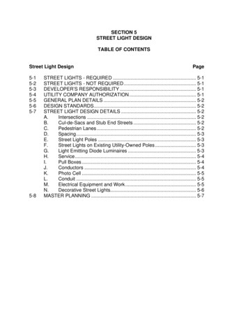
E.Compare the light locations to intersecting property lines, driveways,pedestrian lanes, and other obstructions as follows:1.If the location falls close to a property line and it can be adjusted tothe property line while staying within the maximum spacing allowed,then the adjustment should be made.2.Generally, street lights should be situated at intersecting propertylines for residential lots and parcels with minimal frontage (75 feetor less). The light spacing may have to be unbalanced, withadditional lights being added, to attain this and still comply with themaximum spacing allowed.3.Street light locations shall be adjusted to miss driveways, existingutility poles, and other obstructions by at least five feet.F.Where utility-owned poles with overhead electric power lines exist, theserving utility company shall be contacted to determine if the street lightscan be installed on the poles. When a street light location falls within 25feet of an existing electric power pole, arrangements should be made forthe utility company to install the light on their pole in accordance withSection 5-7(F).G.Street light locations on Arterial and Thoroughfare streets should beadjusted, when possible, to obtain a more uniform light distribution if thereare existing street lights on the opposite side of the street.
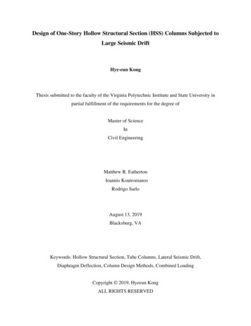
5130L54W-6210L38W-4310L38W-4310L46W-5130L46W-5130L
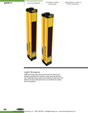
ALLOWEDPREFERREDSTREET LIGHT IS PERMITTED ON THE OPPOSITESIDE IF CURB RETURN IS AVAILABLE.THIS CONFIGURATIONIS ALSO PERMITTED.D/2
B. For planned developments, residential, commercial, and industrial developments where the internal streets are not offered for dedication, a street lighting system will not be required for the i