Transcription
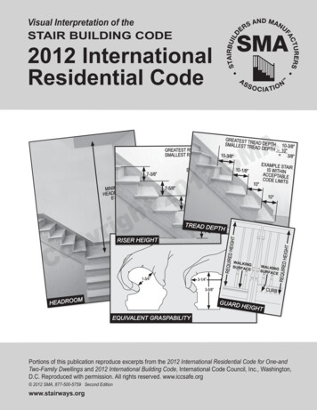
Visual Interpretation of theSTAIR BUILDING CODE2012 InternationalResidential ”TREAD DEPTH7-3/4”TRISER HEIGHTD ��AMGREATEST TRSMALLEST TR EAD DEPTH 10-3/8”EAD DEPTH7-3/4”– 10”GREATEST RISE 3/8”SMALLEST RISE – 7-3/8” 10-3/8” 3/8”EXAMPLE STAIR10-1/8”IS WITHINEXAMPLE STAIRACCEPTABLEIS WITHINCODE LIMITSACCEPTABLE10”CODE GHTEQUIVALENT GRASPABILITYPortions of this publication reproduce excerpts from the 2012 International Residential Code for One-andTwo-Family Dwellings and 2012 International Building Code, International Code Council, Inc., Washington,D.C. Reproduced with permission. All rights reserved. www.iccsafe.org 2012 SMA, 877-500-5759 Second Editionwww.stairways.org
About this DocumentTo the UserThe Stairbuilders and Manufacturers Associationpublishes visual interpretations of BuildingCodes to be accurate pictorial material void ofeditorial comment to aid in the understanding ofthe written code text. We provide this documentas a learning tool to aid designers, builders,homeowners, building officials, stair builders,and others in the shelter industry to accuratelyand consistently interpret the building coderelated to stairways.If you find this document to be of significantvalue, then you will find it equally beneficial toassociate with a member of the StairbuildersManufacturers Association (SMA). Themembers of the SMA have taken on the taskof influencing the development of responsibleand functional building codes. They are thevery individuals effectively communicatingconsistent interpretation of each stair code. Aresulting product of their effort is this VisualInterpretation. SMA members know their craftof Stair Design and Construction and theyknow Building Codes. You are encouragedto contact a member of the SMA before youbegin your next stairway project. Our Membersproudly display the “SMA Member” logo.The SMA has participated in the model codedevelopment process since 1988. We support theInternational Code Council’s (ICC) developmentprocess through our membership and arerecognized and respected for our responsibleefforts at code reform and interpretation inaddition to our trade and industry experiencethat we bring to the table. This experience andreputation is an asset to our continued effortsto provide safe stairways and reduce stairwayaccidents while allowing freedom of design, andaesthetic properties of preference.thigryopIn addition to our experience in the codedevelopment process we provide technicalwriting and graphics assistance related to theIRC and IBC Code Commentaries as publishedby the ICC for each edition.CThe SMA wishes to thank the ICC for theirpermission to print portions of the IRC and in fullrecognition of our responsibility to educate andinform we invite your feedback and comments.This document is provided electronically to thosewho wish to download it from www.stairways.org. It may not be printed, copied or used inpart by any means in any other document,presentation, publication or website except bywritten permission of the SMA. Printed copiesare available from the SMA. This document isnot to be posted on any website. Providing alink to the SMA Bookstore where copies may bepurchased is apprecieated.AMS2102The Stair IndustryDedicated to Safety & QualityConsider MembershipIf your work is related to stairs and you canprescribe to the ethics and quality standardsof the SMA you may qualify for membership.To learn more about the SMA go to our websitewww.stairways.org, and contact us or call tollfree 877-500-5759.
SECTION R311.7 STAIRWAYSR311.7.1 Width.Stairways shall not be less than 36 inches (914 mm) inclear width at all points above the permitted handrailheight and below the required headroom height.PHOTO 1. Handrails shall not project more than 4.5inches (114 mm) on either side of the stairway PHOTO2 and the minimum clear width of the stairway atand below the handrail height, including treads andlandings, shall not be less than 31½ inches (787 mm)where a handrail is installed on one side and 27 inches(698 mm) where handrails are provided on both sidesPHOTO 3.Exception: The width of spiral stairways shall be inaccordance with Section R311.7.10.1.See PHOTO 40 (page 15).MINIMUM 36” CLEAR O 2AMS2102CTWO HANDRAILSMINIMUM 27”ONE HANDRAILMINIMUM 31-1/2”PHOTO 1PHOTO 3 2012 Stairbuilders and Manufacturers Association Interpretation of IRC 2012 www.stairways.org 3
R311.7.2 Headroom.The minimum headroom in all parts of the stairwayshall not be less than 6 feet 8 inches (2032 mm)measured vertically from the sloped line adjoiningthe tread nosing PHOTO 4 or from the floor surfaceof the landing or platform on that portion of thestairway. PHOTO 5.Exception: Where the nosings of treads at theside of a flight extend under the edgeof a floor opening through which thestair passes, the floor opening shall beallowed to project horizontally into therequired headroom a maximum of 4¾inches (121 mm). PHOTO ��-8”AMS2102PHOTO 5CMAXIMUMPROJECTION4¾ INCHESPHOTO 4LIMIT OFNOSINGEXTENDINGUNDERFLOOROPENINGPHOTO 6 2012 Stairbuilders and Manufacturers Association Interpretation of IRC 2012 www.stairways.org 4
R311.7.3 Vertical rise.A flight of stairs shall not have a vertical rise larger than 12 feet (3658 mm) between floor levels or landings.R311.7.4 Walkline.The walkline across winder treads shall be concentric to the curved direction of travel through the turn andlocated 12 inches (305 mm) from the side where the winders are narrower. The 12-inch (305 mm) dimensionshall be measured from the widest point of the clear stair width at the walking surface of the winder.DRAWING 7 figures A-F. If winders are adjacent within the flight, DRAWING 9 (p. 6) the point of thewidest clear stair width of the adjacent winders shall be used. DRAWING 7 figures E-F.thigryopAM102S2CDRAWING 7R311.7.5 Stair treads and risers.Stair treads and risers shall meet therequirements of this section. For the purposesof this section all dimensions and dimensionedsurfaces shall be exclusive of carpets, rugs orrunners. DRAWING 8.DRAWING 8 2012 Stairbuilders and Manufacturers Association Interpretation of IRC 2012 www.stairways.org 5
R311.7.5.1 Risers.The maximum riser height shall be 7¾ inches (196mm). The riser shall be measured vertically betweenleading edges of the adjacent treads. PHOTO 10. Thegreatest riser height within any flight DRAWING 9of stairs shall not exceed the smallest by more than ⅜inch (9.5 mm). PHOTO 11. Risers shall be vertical orsloped from the underside of the nosing of the treadabove at an angle not more than 30 degrees (0.51rad) from the vertical. PHOTO 12. Open risers arepermitted provided that the opening between treadsdoes not permit the passage of a 4-inch diameter (102mm) sphere. PHOTO 13. See Exception to the right.ICC DEFINITION - from Chapter 2 IRC and IBCFlight - a continuous run of rectangular treads or winders or any combination thereof from one landing to anotherMINIMUM DEPTH10”2thigryopCS201DRAWING 97-3/8”7-3/4”7-3/8” 3/8”EXAMPLE STAIRIS WITHINACCEPTABLECODE LIMITS7-5/8”7-5/8”PHOTO 11SLOPE OFRISER MAY NOTEXCEED 30 7-3/4”MODIFIED TO RESTRICTPASSAGE OF A 4” SPHEREIF TOTAL RISE IS LESSTHAN 30”, 4” SPHERERULE DOES NOT APPLY30 PHOTO 12GREATEST RISESMALLEST RISE –7-5/8”MAXIMUMRISER HEIGHT7-3/4”PHOTO 10AMPHOTO 13 2012 Stairbuilders and Manufacturers Association Interpretation of IRC 2012 www.stairways.org 6
R311.7.5.1 Risers. (continued)Exception: The opening between adjacent treads isnot limited on stairs with a total rise of 30inches (762 mm) or less. PHOTO 13R311.7.5.2 Treads.The minimum tread depth shall be 10 inches (254mm). The tread depth shall be measured horizontallybetween the vertical planes of the foremost projectionof adjacent treads and at a right angle to the tread’sleading edge. PHOTO 14. The greatest tread depthwithin any flight DRAWING 9 of stairs shall notexceed the smallest by more than ⅜ inch (9.5 mm).PHOTO 14.R311.7.5.2.1 Winder Treads.Winder treads shall have a minimum tread depth of10 inches (254 mm) measured between the verticalplanes of the foremost projection of adjacent treadsat the intersections with the walkline. Winder treadsshall have a minimum tread depth of 6 inches (152mm) at any point within the clear width of thestair. DRAWING 15 Within any flight of stairs,DRAWING 9 the largest winder tread depth at thewalkline shall not exceed the smallest winder treadby more than 3/8 inch (9.5 mm). DRAWING 16.Consistently shaped winders at the walkline shall beallowed within the same flight of stairs as rectangulartreads and do not have to be within 3/8 inch (9.5 mm)of the rectangular tread depth. DRAWING 16htgiryopGREATEST TREAD DEPTH 10-3/8”SMALLEST TREAD DEPTH – 10” 3/8”10-1/8”10-3/8”10”AMS2102EXAMPLE STAIRIS WITHINACCEPTABLECODE LIMITS10”10”PHOTO 14CDRAWING 15DRAWING 16 2012 Stairbuilders and Manufacturers Association Interpretation of IRC 2012 www.stairways.org 7
ICC DEFINITION - from Chapter 2 IRC and IBCWinder - A tread with non-parallel edgesthigryopAM102S2C 2012 Stairbuilders and Manufacturers Association Interpretation of IRC 2012 www.stairways.org 8
R311.7.5.3 Nosings.The radius of curvature at the nosing shall be nogreater than 9/16 inch (14 mm). PHOTO 17. A nosingnot less than ¾ inch (19 mm) but not more than1¼ inches (32 mm) shall be provided on stairwayswith solid risers. PHOTO 18. The greatest nosingprojection shall not exceed the smallest nosingprojection by more than ⅜ inch (9.5 mm) betweentwo stories, including the nosing at the level of floorsand landings. PHOTO 19. Beveling of nosings shallnot exceed ½ inch (12.7 mm). PHOTO 20.Exceptions: A nosing is not required where the treaddepth is a minimum of 11 inches (279mm).RADIUS OFCURVATURECANNOT EXCEED9/16”PHOTO 17TREAD OVERHANGMINIMUM 3/4”MAXIMUM 1-1/4”NOTE: SEEEXCEPTION 1 ABOVEPHOTO 18ryopthigC1/2” MAXIMUM BEVELPHOTO 20R311.7.5.4 Exterior wood/plastic composite stairtreads.Wood/plastic composite stair treads shall comply withthe provisions of Section R507.3.AM102S2NOSING PROJECTIONMAY NOT VARY MORETHAN 3/8”PHOTO 19 2012 Stairbuilders and Manufacturers Association Interpretation of IRC 2012 www.stairways.org 9
R311.7.6 Landings for stairways.There shall be a floor or landing at the top andbottom of each stairway. The minimum widthperpendicular to the direction of travel shall be noless than the width of the flight served. DRAWING21. Landings of shapes other than square orrectangular shall be permitted provided the depthat the walk line and the total area is not less thanthat of a quarter circle with a radius equal to therequired landing width. DRAWING 22. Where thestairway has a straight run, the minimum depth inthe direction of the travel shall be not less than 36inches (914 mm).Exception: A floor or landing is not required at thetop of an interior flight of stairs, including stairsin an enclosed garage, provided a door does notswing over the stairs.MINIMUMLANDINGWIDTH BOR MORECSTAIRWIDTH B172068 90 36123612DRAWING 226 43Composite of twoexamples at leftillustrates equalareas.AMS2012thigryop3636R311.7.7 Stairway walking surface.The walking surface of treads and landings ofstairways shall be sloped no steeper than one unitvertical in 48 inches horizontal (2-percent slope).PHOTO 23.MINIMUM LANDINGWIDTH A OR MORESTAIRWIDTH ASpace Required to Safely Turn a Stairway atConnecting Flights is Regulated by Depth atthe Walkline and AreaNOT MORE THAN 1 UNIT VERTICAL IN48 UNITS HORIZONTAL (2% SLOPE)2%2%MAXIMUM SLOPE10” TREAD DEPTH 1-1/4” NOSING .2344”PHOTO 23DIRECTIONOFTRAVELMINIMUM MINIMUM36”36”DOWNUPDRAWING 21 2012 Stairbuilders and Manufacturers Association Interpretation of IRC 2012 www.stairways.org 10
R311.7.8 Handrails.Handrails shall be provided on at least one side ofeach continuous run of treads or flight DRAWING 9(p. 6) with four or more risers. DRAWING 24.VOLUTES, TURNOUTS,STARTING EASINGS ANDSTARTING NEWELS AREALLOWED OVER THELOWEST TREADSTARTINGEASINGFLIGHT 2Wall on left sideof lower flightremoved for clarity.TURNOUTFLIGHT 1AMDRAWING 24R311.7.8.1 Height. Handrailheight, measured verticallyfrom the sloped planeadjoining the tread nosing,or finish surface of rampslope, shall be not less than34 inches (864 mm) and notmore than 38 inches (965mm). PHOTO 25.ryopthigExceptions:1. The use of a volute,turnout or starting easingshall be allowed over thelowest tread. PHOTO 26CS2102VOLUTESTARTING NEWELPHOTO 26HANDRAILHEIGHTFITTINGS USED TOPROVIDE CONTINUOUSTRANSITION AREPERMITTED TO EXCEEDTHE HANDRAIL HEIGHT.MIN. 34”MAX. 38”2. When handrail fittingsor bendings are used toprovide continuous transitionPHOTO 25between flights, transitions atwinder treads, the transitionfrom handrail to guardrail, or used at the start of aflight, the handrail height at the fittings or bendingsshall be permitted to exceed the maximum height.DRAWING 27DRAWING 27 2012 Stairbuilders and Manufacturers Association Interpretation of IRC 2012 www.stairways.org 11
R311.7.8.2 Continuity.Handrails for stairways shall be continuous for thefull length of the flight, DRAWING 27 (p. 11) froma point directly above the top riser of the flight toa point directly above the lowest riser of the flight.DRAWING 28 and PHOTO 29 Handrail ends shallbe returned PHOTO 30 or shall terminate in newelposts or safety terminals. Handrails adjacent to a wallshall have a space of not less than 1½ inch (38 mm)between the wall and the handrails. PHOTO 31HANDRAIL MAY BE INTERRUPTED BY A NEWELExceptions:1. Handrails shall be permitted to beinterrupted by a newel post at the turn.PHOTO 322. The use of a volute, turnout, startingeasing or starting newel shall be allowedover the lowest tread. PHOTO 26 (p.11)S2FLIGHT 2thigHANDRAIL MUSTBE CONTINUOUSryopCFLIGHT 1DRAWING 28AMPHOTO 32102PHOTO 29HANDRAILENDS SHALL BERETURNED1-1/2”PHOTO 30MINIMUMHANDRAILCLEARANCEPHOTO 31 2012 Stairbuilders and Manufacturers Association Interpretation of IRC 2012 www.stairways.org 12
R311.7.8.3 Grip-size.All required handrails shall be of one of the followingtypes or provide equivalent graspability. DRAWING33.CIRCULARDIAMETERProfiles other than Type I and Type II may be determinedto provide equivalent graspability.MINIMUM 1-1/4”MAXIMUM 2”PHOTO 34NON-CIRCULAR1-3/4”thigryopCAMMAX 2-1/4”3-1/4”S2102MAX 2-1/4”EDGE MINIMUMRADIUS 0.01”PERIMETERMINIMUM 4”MAXIMUM 6-1/4”PHOTO 353-5/8”DRAWING 331. Type I. Handrails with a circular cross sectionshall have an outside diameter of at least 1¼ inches(32 mm) and not greater than 2 inches (51 mm).PHOTO 34. If the handrail is not circular, it shallhave a perimeter dimension of at least 4 inches (102mm) and not greater than 6¼ inches (160 mm) with amaximum cross section of dimension of 2¼ inches(57 mm). Edges shall have a minimum radius of 0.01inches (0.25 mm) PHOTO 35.2. Type II. Handrails with a perimeter greater than6¼ inches (160mm) shall have a graspable finger recess area on both sides of the profile. The fingerrecess shall begin within a distance of ¾ inch (19mm) measured vertically from the tallest portion ofthe profile and achieve a depth of at least5/16 inch (8 mm) within ⅞ inch (22 mm) below thewidest portion of the profile. This required depth shallcontinue for at least ⅜ inch (10 mm) to a level thatis not less than 1¾ inches (45 mm) below the tallestportion of the profile. The minimum width of thehandrail above the recess shall be 1¼ inches (32 mm)to a maximum of 2¾ inches (70 mm). Edges shallhave a minimum radius of 0.01 inch (0.25 mm). SEEILLUSTRATIONS NEXT PAGE 2012 Stairbuilders and Manufacturers Association Interpretation of IRC 2012 www.stairways.org 13
PERIMETER GREATERTHAN 6-1/4”FINGERRECESS AREABOTH SIDESWIDTH ABOVE RECESS}}PHOTO 36EDGE MINIMUMRADIUS 0.01”PHOTO 39Handrails with a perimeter greater than6¼ inches (160 mm) shall have a graspable finger recess area on both sides of the profile. PHOTO36.WITHIN 3/4”FINGER RECESSBEGINShtThe finger recess shall begin within a distance of ¾inch (19 mm) measured vertically from the tallestportion of the profile and achieve a depth of at least5/16 inch (8 mm) within ⅞ inch (22 mm) below thewidest portion of the profile. PHOTO 37.CTALLEST PORTIONACHIEVE 5/16”DEPTHAMS2102R311.7.8.4 Exterior wood/plastic compositehandrails. Wood/plastic composite handrails shallcomply with the provisions of Section R507.3.giryopPHOTO 37The minimum width of the handrail above the recessshall be 1¼ inches (32 mm) to a maximum of 2¾inches (70 mm). PHOTO 39. Edges shall have aminimum radius of 0.01 inch (0.25 mm). PHOTO 39.TALLEST PORTIONWITHIN 7/8”OF WIDESTPORTIONACHIEVE 5/16”DEPTH1-3/4”CONTINUED FORAT LEAST 3/8”PHOTO 38MINIMUM 1-1/4”MAXIMUM 2-3/4”TO A LEVEL NOTLESS THAN 1-3/4”R311.7.9 Illumination.All stairs shall be provided with illumination inaccordance with Section R303.6.R311.7.10 Special stairways. Spiral stairways andbulkhead enclosure stairways shall comply with allrequirements of Section R311.7 except as specifiedbelow.R311.7.10.1 Spiral stairways. Spiral stairways arepermitted, provided the minimum clear width at andbelow the handrail shall be 26 inches (660 mm)DRAWING 40 & PHOTO 41 with each tread havinga 7½-inch (190 mm) minimum tread depth at 12inches (914 mm) from the narrower edge. All treadsshall be identical, DRAWING 40 and the rise shallbe no more than 9½ inches (241 mm). A minimumheadroom of 6 feet 6 inches (1982 mm) shall beprovided. PHOTO 40This required depth shall continue for at least ⅜ inch(10 mm) to a level that is not less than 1¾ inches (45mm) below the tallest portion of the profile. PHOTO38. 2012 Stairbuilders and Manufacturers Association Interpretation of IRC 2012 www.stairways.org 14
DOWNCOUNTERCLOCKWISE26”MIN.12”7-1/2” MIN.TREAD WIDTHMINIMUMHEADROOM6’-6”DRAWING 40R311.7.10.2 Bulkhead enclosure stairways.Stairways serving bulkhead enclosures, not part ofthe required building egress, providing access fromthe outside grade level to the basement shall beexempt from the requirements of Sections R311.3 andR311.7 where the maximum height from the basementfinished floor level to grade adjacent to the stairwaydoes not exceed 8 feet (2438 mm) and the grade levelopening to the stairway is covered by a bulkheadenclosure with hinged doors or other approved means.thigryop9-1/2”MAXIMUMRISES2AM10226” MINIMUMWIDTH ATAND BELOWHANDRAILPHOTO 41CDRAWING 42 2012 Stairbuilders and Manufacturers Association Interpretation of IRC 2012 www.stairways.org 15
SECTION R312GUARDSAND WINDOW FALL PROTECTIONR312.1 Guards. Guards shall be provided in accordance withSections R312.1.1 through R312.1.4.R312.1.1 Where required. Guards shall be located alongopen-sided walking surfaces, including stairs, ramps andlandings, that are located more than 30 inches (762 mm)measured vertically to the floor or grade below at any pointwithin 36 inches (914 mm) horizontally to the edge of theopen side. DRAWING 42 (P. 15) Insect screening shall notbe considered as a guard.R312.1.2 Height. Required guards at open-sided walkingsurfaces, including stairs, porches, balconies or landings, shallbe not less than 36 inches (914 mm) high measured verticallyabove the adjacent walking surface, DRAWING 43 adjacentfixed seating or the line connecting the leading edges of thetreads. DRAWING 44Exceptions: 1. Guards on the open sides of stairs shall havea height not less than 34 inches (864 mm) measuredvertically from a line connecting the leading edges of thetreads. DRAWING 44.2. Where the top of the guard also serves as a handrail onthe open sides of stairs, the top of the guard shall not be notless than 34 inches (864 mm) and not more than 38 inches(965 mm) measured vertically from a line connecting theleading edges of the treads. DRAWING 44thigryopAM102S2DRAWING 43CDRAWING 44 2012 Stairbuilders and Manufacturers Association Interpretation of IRC 2012 www.stairways.org 16
R312.1.3 Opening limitations.Required guards shall not have openings from thewalking surface to the required guard height whichallow passage of a sphere 4 inches (102 mm) indiameter. PHOTO 45.MUST NOTALLOWPASSAGE OF4-3/8” SPHEREException: 1. The triangular openings at the openside of a stair, formed by the riser, treadand bottom rail of a guard, shall not allowpassage of a sphere 6 inches (153 mm) indiameter. PHOTO 46.2. Guards on the open sides of stairs shallnot have openings which allow passage ofa sphere 4⅜ inches (111 mm) in diameter.PHOTO 46.AMREQUIRED HEIGHTMUST NOTALLOWPASSAGE OF6” SPHEREMUST NOTALLOWPASSAGE OF 4”SPHEREryopthigCWALKINGSURFACES2102PHOTO 46R312.1.4 Exterior woodplastic composite guards.Woodplastic composite guards shall comply with theprovisions of Section R317.4.PHOTO 45 2012 Stairbuilders and Manufacturers Association Interpretation of IRC 2012 www.stairways.org 17
CHAPTER 2DEFINITIONSR201.3 Terms Defined in other codes. Where terms are not defined in this code such terms shall have meaningsascribed to them as in other code publications of the International Code Council.Note: In order to assure a complete understanding in accordance with above we have listed all the stair relateddefinitions from both the IRC and the IBC (International Building Code). These defined terms appear in italicswithin the document.IRC - Section R202 DefinitionsFLIGHT. A continuous run of rectangular treads or winders or combination thereof from one landing to another.GUARD. A building component or a system of building components located near the open sides of elevatedwalking surfaces that minimizes the possibility of a fall from the walking surface to a lower level.AMHANDRAIL. A horizontal or sloping rail intended for grasping by the hand for guidance or support.S2NOSING. The leading edge of treads of stairs and of landings at the top of stairway flights.STAIRWAY. One or more flights of stairs, either interior or exterior, with the necessary landings and platformsconnecting them to form a continuous and uninterrupted passage from one level to another within or attached to abuilding, porch or deck.WINDER. A tread with nonparallel edges.thig102IBC - Section 1002 Definitions1002.1 Definitions. The following words and terms shall, for the purposes of this chapter and as used elsewherein this code, have the meanings shown herein.ryopALTERNATING TREAD DEVICE. A device that has a series of steps between 50 and 70 degrees (0.87 and1.22 rad) from horizontal, usually attached to a center support rail in an alternating manner so that the user doesnot have both feet on the same level at the same time.CFLIGHT. A continuous run of rectangular treads, winders or combination thereof from one landing to another.GUARD. A building component or a system of building components located at or near the open sides of elevatedwalking surfaces that minimizes the possibility of a fall from the walking surface to a lower level.HANDRAIL. A horizontal or sloping rail intended for grasping by the hand for guidance or support.NOSING. The leading edge of treads of stairs and of landings at the top of stairway flights.SCISSOR STAIR. Two interlocking stairways providing two separate paths of egress located within onestairwell enclosure.STAIR. A change in elevation, consisting of one or more risers.STAIRWAY. One or more flights of stairs, either exterior or interior, with the necessary landings and platformsconnecting them, to form a continuous and uninterrupted passage from one level to another.STAIRWAY, EXTERIOR. A stairway that is open on at least one side, except for required structural columns,beams, handrails and guards. The adjoining open areas shall be either yards, courts or public ways. The othersides of the exterior stairway need not be open.STAIRWAY, INTERIOR. A stairway not meeting the definition of an exterior stairway.STAIRWAY, SPIRAL. A stairway having a closed circular form in its plan view with uniform section-shapedtreads attached to and radiating from a minimum-diameter supporting column.WINDER. A tread with nonparallel edges. 2012 Stairbuilders and Manufacturers Association Interpretation of IRC 2012 www.stairways.org 18
NOTES:AMS2102cut on line and laminate for handy field/desk reference toolht2. Slide rail down and position tallestportion of rail section touching line A-Band left edge touching line A-C. Keephorizontal axis of rail parallel to line A-B.2a. verify beginning of recessis at or above line C-D2b. verify gray box is visibleNOTE: Type II rails have a perimetergreater than 6-1/4 inches and a fingerrecess on each side. If profile isasymmetrical both sides must pass.2. From tallest portionC134"1a. Maximum Width234"1b. Minimum Width1"141c. Tallest Portion limitA 1. Position Widest portion of profile here B3"42. Position Tallest portion of profile here2"7"8C3"82a. Beginning of Finger Recess1d. Verify black box is visible516"D2b. Verify gray box is visibleRequired depthof recessReproduction check: solid line measures 2.75 in. 2012 Stairbuilders and Manufacturers Association www.stairways.org 877-500-5759Range of Controlled Grip SizeINSTRUCTIONS:1. Position the widest portion on A-B lineand left edge touching line A-C. Keephorizontal axis of rail parallel to line A-B.With the rail in position:1a. verify maximum width1b. verify minimum width1c. verify tallest portion is at orbelow the limit line1d. verify black box is visible1. From widest portiongiryopFULL SCALE TYPE II RAIL TESTFull ScaleTYPE ll Rail Test
THE MISSION OF THE SMA IS:To be the Greatest Resource of Knowledge and Tools Contributingto the Success of our Members and the Stair IndustryThe Stairbuilders and Manufacturers Association is dedicated to the prospect that safety and aesthetics, withrespect to stairs, are not mutually exclusive.The SMA is a broad based industry association founded in 1988. Our members include stair builders, stairparts manufacturers, installers, millwork distributors, dealers and interested building products professionals.We are an industry organization run by industry people. Our primary focus is to serve the Stair Industry.Because the SMA represents the people who build, install and sell stair parts and stairways in this country, itis our purpose to defend, test, evaluate and promote products and standards that insure safety in conjunctionwith the growth and prosperity of our industry. For more information about the association or becoming amember visit our website, write, call, or Click Here.The Stairbuilders andManufacturers AssociationToll Free: 877-500-5759Website: www.stairways.orgEmail: SMA@stairways.orgthigryopAM102S2C 2012 Stairbuilders and Manufacturers Association Interpretation of IRC 2012 www.stairways.org 20 2012 Stairbuilders and Manufacturers Association Interpretation of IRC 2012 www.stairways.org 20This material contains information which is proprietary to and copyrighted by International Code Council, Inc. Portions of the information copyrighted by international Code council, Inc. have been obtained andreproduced with permission by International Code Council, Inc., Washington, D.C. The acronym “ICC” and the ICC logo are trademarks and service marks of the ICC. All rights reserved. www.iccsafe.org
the written code text. We provide this document as a learning tool to aid designers, builders, homeowners, building officials, stair builders, and others in the shelter industry to accurately and consistently interpret the building code related to stairways. The SMA has participated in the model cod