Transcription
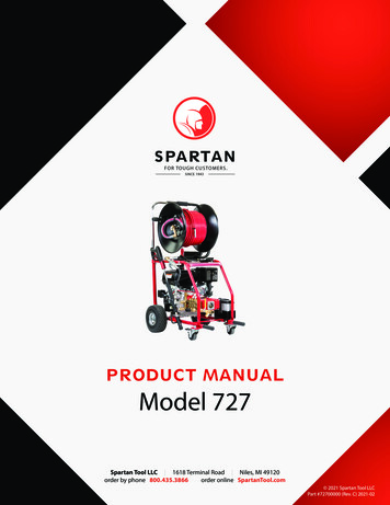
PRODUCT MANUALModel 727Spartan Tool LLC 1618 Terminal Road Niles, MI 49120order by phone 800.435.3866order online SpartanTool.com 2021 Spartan Tool LLCPart #72700000 (Rev. C) 2021-02
ContentsWARNINGS . . . . . . . . . . . . . . . . . . . . . . . . . . . . . . . . . . . . . . . . . . . . . . . . . . . . . . . . . . . . . . . . . . . . . . . . . . . . . . . . . . . . . . . . . . . . . . . . . . . . . . . . . . . . . 4TECHNICAL INFORMATION. . . . . . . . . . . . . . . . . . . . . . . . . . . . . . . . . . . . . . . . . . . . . . . . . . . . . . . . . . . . . . . . . . . . . . . . . . . . . . . . . . . . . . . . . . . . . . 5TECHNICAL INFORMATION. . . . . . . . . . . . . . . . . . . . . . . . . . . . . . . . . . . . . . . . . . . . . . . . . . . . . . . . . . . . . . . . . . . . . . . . . . . . . . . . . . . . . . . . . . . . . . 6DESCRIPTION—COMPONENTS . . . . . . . . . . . . . . . . . . . . . . . . . . . . . . . . . . . . . . . . . . . . . . . . . . . . . . . . . . . . . . . . . . . . . . . . . . . . . . . . . . . . . . . . . . 7NEW UNIT START-UP. . . . . . . . . . . . . . . . . . . . . . . . . . . . . . . . . . . . . . . . . . . . . . . . . . . . . . . . . . . . . . . . . . . . . . . . . . . . . . . . . . . . . . . . . . . . . . . . . . . . 8Before Running Unit. . . . . . . . . . . . . . . . . . . . . . . . . . . . . . . . . . . . . . . . . . . . . . . . . . . . . . . . . . . . . . . . . . . . . . . . . . . . . . . . . . . . . . . . . . . . . . . . . . . . . . . . . . . . 8DAILY OPERATION . . . . . . . . . . . . . . . . . . . . . . . . . . . . . . . . . . . . . . . . . . . . . . . . . . . . . . . . . . . . . . . . . . . . . . . . . . . . . . . . . . . . . . . . . . . . . . . . . . . . . . 9Pre-Check. . . . . . . . . . . . . . . . . . . . . . . . . . . . . . . . . . . . . . . . . . . . . . . . . . . . . . . . . . . . . . . . . . . . . . . . . . . . . . . . . . . . . . . . . . . . . . . . . . . . . . . . . . . . . . . . . . . . . . 9JETTING OPERATION & PROCEDURES. . . . . . . . . . . . . . . . . . . . . . . . . . . . . . . . . . . . . . . . . . . . . . . . . . . . . . . . . . . . . . . . . . . . . . . . . . . . . . . . . . . 10Starting. . . . . . . . . . . . . . . . . . . . . . . . . . . . . . . . . . . . . . . . . . . . . . . . . . . . . . . . . . . . . . . . . . . . . . . . . . . . . . . . . . . . . . . . . . . . . . . . . . . . . . . . . . . . . . . . . . . . . . . 10Stopping. . . . . . . . . . . . . . . . . . . . . . . . . . . . . . . . . . . . . . . . . . . . . . . . . . . . . . . . . . . . . . . . . . . . . . . . . . . . . . . . . . . . . . . . . . . . . . . . . . . . . . . . . . . . . . . . . . . . . . 10General Procedures. . . . . . . . . . . . . . . . . . . . . . . . . . . . . . . . . . . . . . . . . . . . . . . . . . . . . . . . . . . . . . . . . . . . . . . . . . . . . . . . . . . . . . . . . . . . . . . . . . . . . . . . . . . . 10Pulse Control. . . . . . . . . . . . . . . . . . . . . . . . . . . . . . . . . . . . . . . . . . . . . . . . . . . . . . . . . . . . . . . . . . . . . . . . . . . . . . . . . . . . . . . . . . . . . . . . . . . . . . . . . . . . . . . . . . 11Residue . . . . . . . . . . . . . . . . . . . . . . . . . . . . . . . . . . . . . . . . . . . . . . . . . . . . . . . . . . . . . . . . . . . . . . . . . . . . . . . . . . . . . . . . . . . . . . . . . . . . . . . . . . . . . . . . . . . . . . . 11Septic Tanks and Manhole Entrances. . . . . . . . . . . . . . . . . . . . . . . . . . . . . . . . . . . . . . . . . . . . . . . . . . . . . . . . . . . . . . . . . . . . . . . . . . . . . . . . . . . . . . . . . . . 12PRESSURE WASHING INSTRUCTIONS. . . . . . . . . . . . . . . . . . . . . . . . . . . . . . . . . . . . . . . . . . . . . . . . . . . . . . . . . . . . . . . . . . . . . . . . . . . . . . . . . . . . 13JETTING NOZZLES . . . . . . . . . . . . . . . . . . . . . . . . . . . . . . . . . . . . . . . . . . . . . . . . . . . . . . . . . . . . . . . . . . . . . . . . . . . . . . . . . . . . . . . . . . . . . . . . . . . . . 14CARE & MAINTENANCE. . . . . . . . . . . . . . . . . . . . . . . . . . . . . . . . . . . . . . . . . . . . . . . . . . . . . . . . . . . . . . . . . . . . . . . . . . . . . . . . . . . . . . . . . . . . . . . . . 15Engine . . . . . . . . . . . . . . . . . . . . . . . . . . . . . . . . . . . . . . . . . . . . . . . . . . . . . . . . . . . . . . . . . . . . . . . . . . . . . . . . . . . . . . . . . . . . . . . . . . . . . . . . . . . . . . . . . . . . . . . . 15Pump . . . . . . . . . . . . . . . . . . . . . . . . . . . . . . . . . . . . . . . . . . . . . . . . . . . . . . . . . . . . . . . . . . . . . . . . . . . . . . . . . . . . . . . . . . . . . . . . . . . . . . . . . . . . . . . . . . . . . . . . . 15Battery. . . . . . . . . . . . . . . . . . . . . . . . . . . . . . . . . . . . . . . . . . . . . . . . . . . . . . . . . . . . . . . . . . . . . . . . . . . . . . . . . . . . . . . . . . . . . . . . . . . . . . . . . . . . . . . . . . . . . . . . 15Freeze Protection. . . . . . . . . . . . . . . . . . . . . . . . . . . . . . . . . . . . . . . . . . . . . . . . . . . . . . . . . . . . . . . . . . . . . . . . . . . . . . . . . . . . . . . . . . . . . . . . . . . . . . . . . . . . . . 152
TROUBLESHOOTING . . . . . . . . . . . . . . . . . . . . . . . . . . . . . . . . . . . . . . . . . . . . . . . . . . . . . . . . . . . . . . . . . . . . . . . . . . . . . . . . . . . . . . . . . . . . . . . . . . . 16PARTS & ACCESSORIES . . . . . . . . . . . . . . . . . . . . . . . . . . . . . . . . . . . . . . . . . . . . . . . . . . . . . . . . . . . . . . . . . . . . . . . . . . . . . . . . . . . . . . . . . . . . . . . . . 18How to Use the Parts & Accessories Section. . . . . . . . . . . . . . . . . . . . . . . . . . . . . . . . . . . . . . . . . . . . . . . . . . . . . . . . . . . . . . . . . . . . . . . . . . . . . . . . . . . . . 18Final Assembly (72700000). . . . . . . . . . . . . . . . . . . . . . . . . . . . . . . . . . . . . . . . . . . . . . . . . . . . . . . . . . . . . . . . . . . . . . . . . . . . . . . . . . . . . . . . . . . . . . . . . . . . . 19Frame Assembly (72704100) . . . . . . . . . . . . . . . . . . . . . . . . . . . . . . . . . . . . . . . . . . . . . . . . . . . . . . . . . . . . . . . . . . . . . . . . . . . . . . . . . . . . . . . . . . . . . . . . . . . 22Reel Assembly (72727700). . . . . . . . . . . . . . . . . . . . . . . . . . . . . . . . . . . . . . . . . . . . . . . . . . . . . . . . . . . . . . . . . . . . . . . . . . . . . . . . . . . . . . . . . . . . . . . . . . . . . 24Pump Assembly (72726200). . . . . . . . . . . . . . . . . . . . . . . . . . . . . . . . . . . . . . . . . . . . . . . . . . . . . . . . . . . . . . . . . . . . . . . . . . . . . . . . . . . . . . . . . . . . . . . . . . . . 26Pump—Exploded View . . . . . . . . . . . . . . . . . . . . . . . . . . . . . . . . . . . . . . . . . . . . . . . . . . . . . . . . . . . . . . . . . . . . . . . . . . . . . . . . . . . . . . . . . . . . . . . . . . . . . . . . 28Pump Torque Specifications. . . . . . . . . . . . . . . . . . . . . . . . . . . . . . . . . . . . . . . . . . . . . . . . . . . . . . . . . . . . . . . . . . . . . . . . . . . . . . . . . . . . . . . . . . . . . . . . . . . . 30Pump Repair Kits . . . . . . . . . . . . . . . . . . . . . . . . . . . . . . . . . . . . . . . . . . . . . . . . . . . . . . . . . . . . . . . . . . . . . . . . . . . . . . . . . . . . . . . . . . . . . . . . . . . . . . . . . . . . . . 30Plunger Packaging Kits (72726050). . . . . . . . . . . . . . . . . . . . . . . . . . . . . . . . . . . . . . . . . . . . . . . . . . . . . . . . . . . . . . . . . . . . . . . . . . . . . . . . . . . . . . . . . . . . . 30Valve Assembly Kit (72726051). . . . . . . . . . . . . . . . . . . . . . . . . . . . . . . . . . . . . . . . . . . . . . . . . . . . . . . . . . . . . . . . . . . . . . . . . . . . . . . . . . . . . . . . . . . . . . . . . 30Oil Seal Kit (72726052). . . . . . . . . . . . . . . . . . . . . . . . . . . . . . . . . . . . . . . . . . . . . . . . . . . . . . . . . . . . . . . . . . . . . . . . . . . . . . . . . . . . . . . . . . . . . . . . . . . . . . . . . 30Unloader (72726053)—Exploded View . . . . . . . . . . . . . . . . . . . . . . . . . . . . . . . . . . . . . . . . . . . . . . . . . . . . . . . . . . . . . . . . . . . . . . . . . . . . . . . . . . . . . . . . . 31Unloader Repair Kit (72726092) . . . . . . . . . . . . . . . . . . . . . . . . . . . . . . . . . . . . . . . . . . . . . . . . . . . . . . . . . . . . . . . . . . . . . . . . . . . . . . . . . . . . . . . . . . . . . . . . 33Adapter Assembly, 3/8 to 1/4. . . . . . . . . . . . . . . . . . . . . . . . . . . . . . . . . . . . . . . . . . . . . . . . . . . . . . . . . . . . . . . . . . . . . . . . . . . . . . . . . . . . . . . . . . . . . . . . . . . 33Handgun Lance Nozzle Assembly (77799800). . . . . . . . . . . . . . . . . . . . . . . . . . . . . . . . . . . . . . . . . . . . . . . . . . . . . . . . . . . . . . . . . . . . . . . . . . . . . . . . . . . 33Optional Accessories. . . . . . . . . . . . . . . . . . . . . . . . . . . . . . . . . . . . . . . . . . . . . . . . . . . . . . . . . . . . . . . . . . . . . . . . . . . . . . . . . . . . . . . . . . . . . . . . . . . . . . . . . . . 34WARRANTY INFORMATION. . . . . . . . . . . . . . . . . . . . . . . . . . . . . . . . . . . . . . . . . . . . . . . . . . . . . . . . . . . . . . . . . . . . . . . . . . . . . . . . . . . . . . . . . . . . . 353
Warnings Read the safety and operating instructions before using any Spartan Tool product. Drain and sewer cleaning can be dangerous ifproper procedures are not followed and appropriate safety gear is not utilized. Read the engine owners’ manual for instructions andsafety precautions on engine operation. Gasoline is extremely flammable and is explosive under certain conditions. Refuel in a well ventilated area with the engine stopped. Do not smoke or allow flames or sparks in the area where the engine isrefueled or where gasoline is stored. Do not overfill the fuel tank (there should be no fuel in the filler neck). After refueling, make sure the tank cap is closed properlyand securely. Explosive fuel can cause fires and severe burns. Fuel is flammable and its vapors can ignite. Store fuel only in approved containers, inwell ventilated, unoccupied buildings. Do not fill the fuel tank while the engine is hot or running, since spilled fuel could ignite if itcomes in contact with hot parts or sparks from ignition. Do not start the engine near spilled fuel. Never use fuel as a cleaning agent. Before starting unit, be sure to wear personal protective equipment such as safety goggles or face shield and protective clothingsuch as gloves, coveralls or raincoat, rubber boots with metatarsal guards, and hearing protection. Carbon monoxide exhaust and/or gasoline fumes from this equipment can create a hazardous atmosphere in confined spaces (whichmay include, but are not limited to, manholes and septic tanks), closed garages or other areas which may not be properly ventilated.In particular, excess gasoline fumes can create an explosion hazard. Such hazardous atmospheres can cause death or severe injury.Do not operate this equipment with its cart (used to house the engine and gasoline tank) located in any confined space or area withinadequate ventilation. Operate this equipment only when the cart is located outdoors or in an open, well-ventilated area. Ensure the jet hose has been placed in the pipe a minimum of 3 feet before engaging the water pressure to prevent the hose fromcoming out of the pipe prematurely and causing injury. Always shut off the water pressure before pulling the hose out of the pipe. Mark the hose a minimum of 6 feet from the end to helpensure the hose is not accidentally pulled out of the pipe while still under pressure. Shut off the water pressure when the hose markis encountered.CAUTION: Portions of the system can still be under pressure even if the unit is not operating. Never point the wash gun at anyone while operating the unit. Injury may result. Drains and sewer can carry bacteria and other infectious micro-organisms or materials which can cause death or severe illness. Avoidexposing eyes, nose, mouth, ears, hands, and cuts and abrasions to waste water or other potentially infectious materials during drainand sewer cleaning operations. To further help protect against exposure to infectious materials, wash hands, arms and other areasof the body, as needed, with hot, soapy water and, if necessary, flush mucous membranes with water. Also, disinfect potentiallycontaminated equipment by washing such surfaces with a hot soapy wash using a strong detergent. For any questions, contact Spartan Tool at the address shown below.CONTACT USSpartan Tool LLC1618 Terminal RodNiles, MI 49120800.435.3866SpartanTool.com4CALIFORNIA PROP. 65This product may contain anextremely small amount of lead in thecoating. Lead is a material known tothe State of California to cause canceror reproductive toxicity.
Technical InformationGENERALPipe SizesUp to 6" diameterMax water delivery4.8 GPMMax pressure delivery3,000 PSIWeight—power unit166 lbsWeight—reel with hose54 lbsUnit size23"W x 35"L x 47"HENGINEHorsepower14 HP, Kohler CH440Electric startStandardLow oil alert systemStandardCylinders1Bore & stroke3.5 x 2.7Full throttle RPM3,200FuelGasoline (1.85 gal capacity)OilSAE 10W30 (1.16 qt capacity)SparkplugChampion RC12YCCoolingAirBattery12 VDC, 17.5 Amp hour, 310 CCABack-up starterRecoilChokeManualPUMPPumpTriplex plunger, GIANTMax pressure3,000 PSIMax water output4.8 GPMMax temperature160 FMax RPM3,400Plungers35
Technical InformationFEATURES2 wheel cart with 10" pneumatic tires and swivel—locking front casters200 feet of high pressure 5 16" I.D. working hose75 feet of high pressure 3 16" I.D. working hoseNozzles: (1/4 NPT) for 5 16" I.D. hose 72705100 thruster for distance 72705200 cleaning for penetration JH-SPNR1 nozzle - spinner (1 8 NPT) for 3 16" I.D. hose 72705400 thruster for distance (1 8 NPT) 72705500 cleaning for penetration (1 8 NPT)Pulsation feature for improved hose feeding and retrievalThermal dump feature controls heat buil-up during extended periods ofoperation with no high pressure flowDetachable dual-action hose reel0 to 5,000 PSI pressure gauge providedWash wand with detachable trigger gunTip cleanerGloves6
New Unit Start-UpBEFORE RUNNING UNITLocate the small cardboard box packed with the following materials: (1) Spartan 727 Product Manual (1) Engine Owners Manual (1) 3 8" to 1/4" quick disconnect adapter (1) Sparkplug wrench (1) Nozzle cleanerPackaged separately: (1) Trigger wash wand (1) 75' x 3 16" I.D. jetting hose with nozzleNOTE If any of the above items are missing, contact Spartan Tool Customer Service at800.435.3866 or by email at CustomerService@SpartanTool.com.Locate the battery. There are two battery terminals. One is connected. One is not. Loosen the nut on the disconnected terminal with awrench. Connect the loose cable to the terminal between the nut and the "U" shaped bracket on the battery. Tighten securely (20 to 40in-lbs).7
Daily OperationPRE-CHECK1.Check engine oil (SAE 10W30) by reading the dipstick. (Refer to engine owners manual.)2.Check pump oil (use only Giant Synthetic or a 15W-50 synthetic motor oil).3.Check engine fuel. Fill as necessary. Remove the rear hose reel retaining pins to allow the hose reel to be tilted forward for access tothe engine fuel tank.4.Check pump inlet line strainer for cleanliness before each use. Never run a unit without a strainer.5.Check the jetting nozzle for possible plugged jet holes using visual inspection and the nozzle cleaning tool. If plugged, use thenozzle cleaner to carefully clear the obstruction (and then rinse). CAUTION: DO NOT ENLARGE THE JET HOLES OF THE NOZZLE. Operating the jetter with jetting nozzle holes plugged ORenlarged will interfere with the performance of the machine.6.Use a good-quality 5 8" or larger garden hose connected to an adequate water supply. Connect hose to hot or cold water faucet. To check for a required minimum 4 GPM water supply, open water spigot valve and time water flow through the garden hoseand into a one-gallon container. If the container fills in 15 seconds or less, the water supply has adequate flow to supply thejetter. Insufficient water supply will cause pump to cavitate.PRE-CHECK1.Attach the garden hose from a water supply to the jetter. If a hot water supply is used, do not allow water temperature to exceed 140 F, that is thermo-dump valve setting.2.Attach jetter hose to the unit (do not attach the jetting nozzle at this time).3.Prime the system by turning the supply hose valve on, turning the pump inlet valve on, and turning the jetter hose reel controlvalve on. Allow the water to flow until the air is purged from the system.4.Turn jetter hose reel control valve off.5.Attach selected jetting nozzle to the hose finger tight.6.Mark a location on hose 3 feet from the jetting nozzle end with a band of tape. Use that mark to determine when jetting nozzle isnear access hole. Avoid injury from unconfined jetting nozzles. Place the hose and nozzle at least 3 feet into the line to be cleaned before startingthe engine. Turn the hose reel valve on (valve must be on for engine to start).7.Turn the engine fuel valve on. Start the engine at a reduced (about 1/4) throttle setting. Allow 1 to 2 minutes for the engine to warmup, then fully open the throttle. NOTE: Only operate the Model 727 in the upright position. Never allow the unit to be laid on its back or on its side. Damage tothe engine will result.8.8You are now ready to start jetting.
Jetting Operation & ProceduresSTARTINGBefore starting unit, be sure to wear personal protective equipment, such as safety goggles or face shield, and protective clothing suchas gloves, coveralls or raincoat, rubber boots with metatarsal guards, and hearing protection.1.Keep jetting hose at least 3 feet into pipe line access hole. Do not remove hose from line at any time while under power.2.Adjust regulator control knob to 3,000 PSI. WARNING: Do not exceed 3,000 PSI. Injury or machine damage may result. Control hose water pressure and flow at the hosereel valve. Open and close the valve slowly for smooth engine response. Never run the machine with the hose reel valve in the closed position for more than 1 to 2 minutes. Extended shut-off causes thewater recycled in the pump to overheat, which will cause the thermal valve to open and vent hot water.3.Begin jetting.STOPPING1.Shut down the engine by reducing to 1/4 throttle before turning the ignition off.2.Shut off the water supply. Disconnect hoses.GENERAL PROCEDURES Jetting hose selection is determined by the size of the line to be cleaned. Use the 5 16" I.D. hose directly from the hose reel for large lines and distances. Use the smaller 3 16" I.D. hose (provided separately) for smaller jobs requiring jetting through traps. Use of the smaller 3 16" jetting hose should be made directly from the pump quick disconnect fitting (using the provided 3 8" to 1/4"adapter) for the best results. For jobs located at distance from the jetting machine, use the trigger wash wand at the end of the 5 16"I.D. hose for flow control and attach the 3 16" I.D. hose to the wash wand. Jetting nozzle selection is made according to the size of the hose used and the type of jetting to be done. See the jetting nozzledescriptions for best applications. If possible, jetting to the approximate far end of the build-up. Pull the jetter hose back at a slow rate (down to about 1 ft/min forheavy drainline accumulation), allowing enough time for the jetting nozzle to wash the pipe clean. For best results, jet from the lower end of the line to be cleaned. Provision may hae to be made to catch accumulation of water duringjetting operation. Hold the jetter hose, release the locking "L" pin on the reel and allow the hose to feed itself into the line to be cleaned. Pushing on thehose to aid in feeding may be required through traps, blockages, and long distances. When jetting a drain line through a trap, you may have to help the jetter hose feed through the trap by grasping it near the entranceof the drain and jabbing the jetting nozzle through the trap with a quick thrusting motion. When jetting from the high end of the line, turn the jetter jose reel valve off occasionally to allow water accumulation to drain pastthe jetting nozzle.9
Jetting Operation & Procedures When obstruction or corners are encountered, it may benecessary to manually rotate the hose (Fig. 1) to enable thehose to feed through the area. This will cause the jettingnozzle to jump over or around those areas. If it becomesnecessary to manually rotate the hose to clear obstructions,any rotations in one direction must be followed by an equalnumber in the opposite direction to prevent kinks frombuilding in the hose. It may also be necessary to move the hose slightly in andout of the drain line to assist the jetting nozzle in cleaningstubborn clogs, obstructions, or tight corners (Fig. 2).FIG. 1FIG. 2PULSE CONTROL The Model 727 comes equipped with a pulsator. The purpose of the pulsation is to assist in moving the water jet hose throughthe pipe. The pulsator unit operates by creating a vibrating or pulsing action on the hose using pressurized water. The pulsing orvibration action reduces hose drag in a pipe by reducing surface contact of the hose on the pipe and with the assistance of the waterjet nozzle, causes the hose to propel itself into a pipe much farther and faster. To engage the pulsator, turn the control knob clockwise (right) all the way to the built-in stop. The vibrating or pulsing actionwill start instantly and the hose will move into the pipe. A slight drop in pressure will be noted on the pressure gauge when thepulsation is engaged. When retrieving the hose from the pipe, pulsating action is not required and by turning the control knobcounterclockwise (left) all the way to the stop, the unit is returned to standard jetting. NOTE: Pulsation control knob must be completely turned in or out to avoid excessive wear on pump and pulsation unit.Excessive use of the pulsator will lead to quicker wear of the jetting hose.RESIDUE Most drain line residue is precipitated (a solid is formed when it falls out of water suspension and collects on drain pipe walls). A3,000 PSI water blast from the jetter can very quickly wash these drain lines clean. Many lines have a deep layer of hard soap and lime residue bonded to the drain pipe wall. In some of these cases you will encountera very slow jetting speed because you are cutting through this hard soap. As an aid to gauging the travel of the jetting hose, mark thehose at intervals with tape or other markers. To clear soap residue, use the cleaning jet nozzles with hot tap water (140 F max). Jet to the far end of the soap residue (jetting canbe very slow, down to 6" per minute). Pull the jet hose out very slowly to allow time for water jets to cut through the soap cake. Attimes, you will wash large tubular sections of soap downstream. WARNING: Hot water can cause severe burns. Wear a face shield, gloves, and a raincoat when using water at hightemperatures.10
Jetting Operation & ProceduresSEPTIC TANKS AND MANHOLEENTRANCES Use a section of 11/2" or 2" PVC pipe with a 45 fitting attachedto the end to aid in feeding the jetter hose into a drain line in aseptic tank or manhole (Fig. 3). Use caution when entering a confined space! FollowOSHA guidelines. Dangerous gases in these areas maybe lethal!FIG. 3Pressure Washing Instructions Attach the handgun and lance with quick disconnect fitting to the 5 16" jetting hose for pressure washing applications. Refer to jettingstart-up procedures. Adjust the Vari-Nozzle at the end of the lance to achieve the best spray pattern for the pressure wash job being done.WARNING: Avoid running the machine with the handgun in the closed position for more than 1 minute.Extended shut-off causes the water recycled in the pump to overheat, which will cause the thermal valve toopen and vent hot water.11
Jetting NozzlesThe following nozzles are provided in sizes to fit both the 5 16" I.D. (1/4 NPT) hose and 3 16" I.D. (1 8 NPT) hose, except for the rotating nozzle,which is only provided to fit the 5 16" I.D. hose.THRUSTER JETTING NOZZLES—FOR DISTANCEThese nozzles have four jets in reverse at a low anglefor maximum thrustOPEN JETTING NOZZLES—FOR PENETRATIONThese nozzles have four jets in reverse at a low angle,plus one forward penetrating jet. These penetratingjetting nozzles are used to jet through grease, ice, orother residue.ROTATING JETTING NOZZLEThis nozzle is used to clean the wall of the sewer lineafter the line has been unclogged.12
Care & MaintenanceENGINE Oil—SAE 10W30 (1.16 qt capacity) Check engine oil with every usage. Make the first engine oil change after (1) month or 20 hours of operation and every (6)months or 100 hours of operation thereafter. Air Cleaner—Dual element type Check air cleaner with every usage. Clean every (3) months or 50 hours of operation. Sediment Cup Check every (6) months or 100 hours of operation. Spark Plug—Champion RC12YC Check every (6) months or 100 hours of operation. Replace every year or 300 hours of operation.PUMP Oil—Giant synthetic or a 15W-50 synthetic motor oil (Capacity: 21 fl oz) Change oil after the first 50 hours of operation, then at regular intervals of 500 hours or less, depending on operating conditions. Inlet strainer Check inlet strainer before every usage to ensure that it is not blocked. Take care to ensure that no dirt or particles are allowed toenter the pump system.WARNING: Do not exceed 3,000 PSI. Injury or machine damage may result.BATTERY 12V DC, 17.5 Amp Hour—310 CCA Maintenance-free battery. See battery for warnings.WARNING: The battery contains sulfuric acid (electrolyte). Contact with skin or eyes may cause severe burns. Wearprotective clothing and a face shield.FREEZE PROTECTIONCold Weather Protection: To avoid damage to the pump and water jet hose, keep the Model 727 from freezing temperatures. If theModel 727 must be stored in freezing temperatures, you must use one of the following methods: Method 1: Use pressurized air to blow out any remaining water left inside pump and hose by using the air blow-out feature(located next to the pressure gauge). Method 2: Attach a short garden hose (not to exceed 4 feet) to the pump inlet valve and put the other end of the garden hoseinto a mixture of 50% antifreeze and 50% water. Cycle antifreeze mixture through the system. When antifreeze flows from theoutlet, the system is protected.13
TroubleshootingPROBLEMLow pressure or flow.Rough/pulsating operation withpressure drop.Water in crankcase.Noisy operation.14POSSIBLE CAUSESCORRECTIVE ACTIONClogged inlet filter or improper size.Clean. Use adequate size.Check more frequently.Inadequate water supply.Check flow available to pump.Worn nozzle.Replace nozzle of proper size.Leaky discharge hose.Repair or replace.Pressure gauge inoperative or notregistering accurately.Check with new gauge. Replace worn ordamaged gauge.Air leak in inlet plumbing.Disassemble, reseal, and reassemble.Worn packing seals.Replace packing seals.Fouled or dirty inlet or discharge valves.Clean inlet and discharge valveassemblies.Worn or plugged relief valve on pump.Clean, reset, and replace.Cavitation.Check suction lines on inlet of pump forrestrictions.Unloader.Check for proper operation.Pump not fully primed.Remove jetter hose at outlet. Turn pumpinlet valve on. Run pump until fullyprimed.Low engine RPM.Check full throttle speed (adjust to 3,200RPM).Pump not fully primed.Remove jetter hose at outlet. Turn pumpinlet valve on. Run pump until fullyprimed.Worn packing.Replace packing.Inlet restriction.Check system for stoppage, air leaks, andcorrectly sized inlet plumbing.Cavitation.Check inlet lines for restrictions and/orproper size.High humidity.Reduce oil change interval.Leakage of crankcase or seals installedbackwards.Replace packing.Worn seals.Replace seals.Pump not fully primed.Remove jetter hose at outlet. Turn pumpinlet valve on. Run pump until fullyprimed.Worn bearings.Replace bearings. Refill crankcase withrecommended lubricant.Cavitation.Check inlet lines for restrictions and/orproper size.Coupler loose on crankshaft.Check and tighten set screws.
TroubleshootingPROBLEMFrequent or premature failure of thepacking.Excessive leakage.POSSIBLE CAUSESCORRECTIVE ACTIONDamaged or worn plungers.Replace plungers.Abrasive material in fluid being pumped.Install proper filtration on pump inletplumbing.Excessive pressure and/or temperature offluid being pumped.Check pressures and fluid inlettemperature. Be sure they are within thespecified range.Over pressure of pumps.Reduce pressure.Running pump dry.Do not run with inadequate water supply.Worn or cracked plungers.Replace plungers.Worn packing/seals.Adjust or replace packing seals.Excessive vacuum.Reduce suction vacuum.Inlet pressure too high.Reduce inlet pressure.15
Parts & AccessoriesHOW TO USE THE PARTS & ACCESSORIES SECTIONSpartan Tool will supply all parts or accessories you require as quickly as possible. In order to do so, we must have information from you,including machine serial number and part numbers.Please record the serial number of your machine in the space provided below:SPARTAN MODEL 727Unit Serial NumberTo order parts, look through the pictures until you find the part you require or anindication of where the part should be. Using the item number from the picture, go tothat number on the adjacent page and check the description to determine if it is the partyou desire.CONTACT USSpartan Tool LLC1618 Terminal RoadNiles, MI 49120800.435.3866SpartanTool.comUsing the part numbers, please contact your Spartan Territory Manager or Spart
If the container fills in 15 seconds or less, the water supply has adequate flow to supply the jetter. Insufficient water supply will cause pump to cavitate. PRE-CHECK 1. Attach the garden hose from a water supply to the jetter. If a hot water supply is used, do not allow water temperature to exceed 140 F, that is thermo-dump valve .