Transcription
SEISMIC CEILINGINSTALLATIONWhat You Need to KnowCode RequirementsSeismic RxTested Solutions
CURRENT SEISMIC CODE: DEVELOPMENT AND ADOPTIONThe Code Official’s RoleThe building code presents minimum design/performance requirements and in some instances prescriptive guidance.The code also sets forth limitations and conditions of use. It is important to know that while the building code establishesthe requirements, the code official has the power to enforce its provisions. Code officials also have the latitude to allowmaterials and methods of construction that are not addressed in the code. Code officials can perform their own analysisof evidence presented or can rely on independent, qualified sources such as ICC-ES to do the analysis and providetheir findings.Purpose of Installation Requirements for Suspended Ceilings Provide a suspension system strong enough to resist lateral forces imposed upon it without failing Prevent border panels from falling from the ceiling planeFederal Emergency Management Agency (FEMA)Seismic performance during large California earthquakes prompted FEMA to address suspended ceiling performanceduring a seismic event. Research and tests demonstrated that industry seismic standards (UBC Standard 25-2) werenot adequate. To support individual panels around the perimeter, FEMA determined that the key to good seismicperformance is a wider wall molding on all sides. This led to the International Building Code requirement for 2"wall molding on all sides.Source: FEMA 302 NEHRP Recommended Provisions for Seismic Regulations for New Buildings and Other StructuresAdoption of the International Building CodeCurrently all 50 states as well as Washington, D.C. and the Virgin Islands use the International Building Code.AlaskaHawaiiHave adopted the International Building Code at a local or state-wide levelSource: x (May 2010)ICC makes every effort to provide current, accurate code adoption information, but in some cases, jurisdictions do not notify ICC of adoptions, amendments,or changes to their codes.How Seismic Design Categories Are DeterminedThe seismic design category must be specified by a professional engineer or registered architect on the project drawingsper ASCE 7. The project requirements which include the seismic design category can be found in Section 1 of thespecification, and on the first page of the structural drawings.2
C OCODED E RREQUIREMENTSEQUIREMENTSInternational Building Code (IBC) allows two paths to determine Seismic Design Category – IBC Section 1613 or ASCE 7Section 11.6. The IBC states that a Seismic Design Category must be established for each construction project based on: Anticipated ground motion Soil type in a specified geographic area Occupancy categoryThese factors are used to evaluate and establish a Seismic Design Category of A, B, C, D, E, or F. The installation ofceilings can be divided into three tiers of increasing requirements: Categories A & B are installed to meet requirements established in ASTM C636 Category C projects must meet those plus additional provisions listed in ASTM E580 Categories D, E & F must follow ASTM C636 and ASTM E580NOTE: Seismic categories are determined for the entire building. This is why the Seismic Design Category informationis on the structural drawings.SUMMARY OF IBC SEISMIC INSTALLATION REQUIREMENTSIBC CATEGORYIBC INSTALLATION REQUIREMENTSA, BCeiling installation should conform to basic minimums established in ASTM C636. 12ga. hanger wires, minimum Hanger wires spaced 4ft on center, maximum, along main beamsHanger wires supporting main beams must be wrapped around themselves a minimum of three fullturns within a 3" lengthHanger wires shall not hang more than one-in-six out-of-plumb, unless a counter-sloping wire orhorizontal brace is providedC Installed to ASTM E580 Seismic Design Category C. Minimum 7/8" wall molding Suspension system must not be attached to the wall moldingMinimum 3/8" clearance on all sidesMinimum 3/8" overlap of the suspension system on the wall molding Ends of main beams and cross tees must be tied together to prevent their spreadingSafety wires required on light fixturesD, E, F Installed to ASTM C636 and ASTM E580 Minimum 2" wall moldingSuspension system must be attached to two adjacent walls – opposite walls must have a 3/4" clearanceEnds of main beams and cross tees must be tied together to prevent their spreading Heavy-duty suspension system Ceiling areas over 1,000 SF must have horizontal restraint wire or rigid bracing Ceiling areas over 2,500 SF must have seismic separation joints or full height partitions Ceilings without rigid bracing must have 2" oversized trim rings for sprinklers and other penetrations Changes in ceiling plane must have positive bracing Cable trays and electrical conduits must be independently supported and braced Suspended ceilings will be subject to special inspection Perimeter support wires within 8"NOTE: Consult your local code professional for information specific to your region.California projects may be governed by DSA and OSHPD.3
ADDITIONAL RESOURCES ON SEISMIC CODES AND REQUIREMENTSContact TechLine at Armstrong (Monday throughFriday – 8:00 a.m. to 5:30 p.m. EST):Phone: 1 877 276 7876Fax: 1-800-572-8324 Email: techline@armstrongceilings.comVisit these code-related websites:ASTM International: www.astm.org National Institute of Building Sciences: www.nibs.orgFEMA: www.fema.govICC-ES: www.icc-es.orgU.S. Geological Survey: www.usgs.govICC-ES Evaluation ServiceICC-ES does technical evaluations of building products, components, methods, and materials. The evaluation processculminates with the issuance of technical engineering reports that directly address the issue of code compliance. Thesereports are extremely useful because regulatory agencies use evaluation reports to help determine code compliance andenforce building regulations; and manufacturers use reports as evidence that their products meet code requirementsand warrant regulatory approval. This is especially important if the products are new and innovative.ICC-ES employs a large staff of professionally licensed architects and civil, structural, mechanical, and fire protectionengineers. The members of the ICC-ES technical staff are experts in the application of model codes, and also haveaccess to historical information relating to product evaluation. When developing acceptance criteria, ICC-ES routinelyseeks input from building industry experts through a process of open public hearings. These hearings are conductedby an independent committee composed of code officials who actually enforce building regulations.IAPMO Evaluation ServiceIAPMO performs technical evaluations of building products, components, methods, and materials. The evaluationprocess culminates with the issuance of technical engineering reports that directly address the issue of codecompliance. These reports are extremely useful because regulatory agencies use evaluation reports to help determinecode compliance and enforce building regulations; and manufacturers use reports as evidence that their productsmeet code requirements and warrant regulatory approval. This is especially important if the products are newand innovative.The Uniform Evaluation Report helps the code official know the product has undergone the highest levels of third-partyscrutiny available. It also documents that the product undergoes IAPMO’s continuous compliance inspection program.All the relevant code compliance information is summarized in the report to assist you in selection, and the code officialin verifying code acceptability. Although an evaluation report is not a guarantee, those products without such a report riskhaving to supply pertinent information to each code official.4
C ARMSTRONGO D E R E Q U ICEILINGSREMENTSSEISMIC TESTED SYSTEMSARMSTRONG CEILINGS SEISMIC TESTED SYSTEMSAlternative Materials and Construction MethodsArmstrong Ceilings has tested many items that have not been submitted to the Engineering Evaluation Report process.We can provide white papers and test reports to document seismic performance; however, many of these products donot have clear code requirements:1 3.2.5 Testing Alternative for Seismic Capacity Determination. As an alternative to the analytical requirements ofSections 13.2 through 13.6, testing shall be deemed as an acceptable method to determine the seismic capacityof components and their supports and attachments. Seismic qualification by testing based upon a nationallyrecognized testing standard procedure, such as ICC-ES AC 156, acceptable to the authority having jurisdiction shallbe deemed to satisfy the design and evaluation requirements provided that the substantiated seismic capacities equalor exceed the seismic demands determined in accordance with Sections 13.3.1 and 13.3.2.1 3.2.6 Experience Data Alternative for Seismic Capacity Determination. As an alternative to the analyticalrequirements of Section 13.2 through 13.6, use of experience data shall be deemed as an acceptable methodto determine the seismic capacity of components and their supports and attachments. Seismic qualification byexperience data based upon nationally recognized procedures acceptable to the authority having jurisdiction shallbe deemed to satisfy the design and evaluation requirements provided that the substantiated seismic capacitiesequal or exceed the seismic demands determined in accordance with Section 13.3.1 and 13.3.2.” Source: ASCE 7, Chapter 13In some cases, there are no clear industry code requirements or acceptance criteria such as: Ceilingsthat do not run wall-to-wallIndirect hung ceilingsAs a result, seismic performance and engineering information cannot be included in an ESR report.In light of this, Armstrong Ceilings has conducted rigorous testing at the State University of New York, University atBuffalo, to demonstrate seismic performance. Test result summaries can be provided to code officials in the form ofwhite papers.For example: In 2004, Armstrong Ceilings led the industry with seismic testing documentation summaries and testprotocols for our Seismic Rx solution. This information set the industry standard and drove the issuance of ESR-1308 in 2006.Products Not Covered by a ReportProviding a valid report to a code official does represent the “gold standard” for installations. A report representsthe safest, least risky method for selecting a seismic ceiling solution. Armstrong Ceilings has tested a number ofproducts that do not appear in a report because these products do not have clear code requirements. We will provideperformance criteria via white paper or test report based on large-scale seismic shake table test results from an IASaccredited test facility (State University of New York, University at Buffalo). A white paper or test report can be obtainedby calling TechLine at 1 877 276-7876.When requesting a white paper or test report, you’ll be asked to provide the following project information:P roject Name Location Product Customer Contact Design Professional Contact5
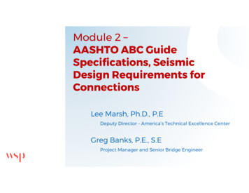
State University of New York, University at BuffaloArmstrong Ceilings has partnered with the State University of New York, University at Buffalo, to test our products for seismicperformance. These tests are performed at the Structural Engineering and Earthquake Simulation Laboratory (SEESL) located inKetter Hall. SEESL is a key equipment site in a nationwide earthquake engineering collaborator – the National Science Foundation’sGeorge E. Brown, Jr. Network for Earthquake Engineering Simulation (NEES). This network allows earthquake engineers andstudents from different institutions to share resources, collaborate on testing, and exploit new computational technologies.Exterior photo of UB’s Structural Engineering and Earthquake SimulationLaboratory (SEESL)SEESL’s twin relocatable shake tablesTHE SEESL FACILITY HAS THE FOLLOWING CAPABILITIES: Three earthquake simulators known as shake tablesA two-story biaxial shaking table system used as non-structural component simulatorA 175 m2 strong reaction wall for reactions to horizontal loading devices (actuators) for large-scale testingA 340 m2 strong testing floor for vertical reactions and tie downs of large-scale modelsA biaxial laminar box for 1.0g soil testing Reconfigurable assemblies of static and dynamic servo-controlled actuators with advanced control systems(STS, Flextest, etc.)A high-performance hydraulic power supply with flow exceeding 6,000 liters per minute (1,600 gallons per minute)High-speed wideband local and wide area gigabit networks interfaced and supported by NEESit services Tele-presence & tele-operations capabilities for local and wide area collaborations in real time Advanced dynamic, pseudo-dynamic, and static testing capabilities including a generic advanced procedure realtime dynamic hybrid testing (RTDHT) Additional information can be found by visiting nees.buffalo.eduFull-scale Seismic TestedArmstrong Ceilings has partnered with the State University of New York, University at Buffalo, to test both standard and nonstandard ceiling systems for seismic performance. Armstrong Ceilings submitted the following: Dynamic Testing – Seismic Qualification by Shake Table Testing Static Testing – Vertical, Compression, and Tension LoadsIBC code allows alternative designs if tests are conducted and evidence of compliance is submitted. Thus, code officialsmay approve other installation designs based upon the following: ection 104.11 Alternative materials, design and methods of construction and equipment.SThe provisions of this code are not intended to prevent the installation of any material or to prohibit any design ormethod of construction not specifically prescribed by this code, provided that any such alternative has been approved.An alternative material, design, or method of construction shall be approved where the building official finds that theproposed alternative meets all of the following:61. The alternative material, design, or method of construction satisfactory and complies with the intent of theprovisions of this code.2. The material, method, or work offered is, for the purpose intended, not less than the equivalent of thatprescribed in this code as it pertains to the following:
2.2. Strength2.3. Effectiveness2.4. Fire Resistance2.5. DurabilityC ARMSTRONGO D E R E Q U ICEILINGSREMENTSSEISMIC TESTED SYSTEMS2.1. Quality2.6. StrengthWhere the alternative material, design, or method of construction is not approved, the building official shallrespond in writing, stating the reasons why the alternative was not approved. ection 104.11.1 Research reports.SSupporting data, where necessary, to assist in the approval of materials or assemblies not specifically provided for inthis code, shall consist of valid research reports from approved sources. ection 104.11.2 TestsSWhenever there is insufficient evidence of compliance with the provisions of this code, or evidence that a material ormethod does not conform to the requirements of this code, or in order to substantiate claims for alternative materialsor methods, the building official shall have the authority to require tests as evidence of compliance to be made atno expense to the jurisdiction. Test methods shall be as specified in this code or by other recognized test standards.In the absense of recognized and accepted test methods, the building official shall approve the testing procedures.Tests shall be performed by an approved agency. Reports of such tests shall be retained by the building official for theperiod required for retention of public records.Source: International Building Code 2021ProductInstallation DetailProductInstallation DetailAxiom BuildingPerimetersPerimeter Pocket with Horizontal DiffuserPerimeter Pocket with Vertical DiffuserSeismicCanopiesCapz MetalWorks MetalWorks WingsOptima CanopiesSoundScapes CanopiesWoodWorks Clouds6' x 6', 12' x 12', and 14' x 14' Formations 12" Axiom Floating 2-sides with Prelude XL ID12" Axiom Floating Cloud with Prelude XL ID6" Axiom Floating 2-sides with Prelude XL ID6" Axiom Floating Cloud with Prelude XL ID16" Axiom TrimInfusions ShapesFormations CurvesSerpentina ClassicSerpentina VaultSerpentina Waves SoundScapes Blades SoundScapes ShapesCategory C Installation per CodeCategory D, E & F Installation per CodeSeismic Corridor with 8" GussetSeismic Corridor with 12" GussetSeismic Joint Clip Main Beam (SJMR15) Fully LoadedSeismic Joint Clip Main Beam (SJMR9) Fully LoadedSeismic Joint Main Beam SpliceSeismic Separation Joint on Prelude XLSeismic Separation Joint on Suprafine XLSTAC – Single Tee Adapter ClipSeismic Rx BERC2 45-degrees to the Wall on Prelude XLBERC2 Fully Loaded on Prelude XLBERC2 on 7897 Shadow Molding with Ultima Vector PanelsBERC2 on Interlude XL HRCBERC2 on Interlude XL HRC with Lights & SprinklersBERC2 on Silhouette XL with Diffusers & SprinklersBERC2 with Prelude XL Intermediate-dutyBERC2 with Suprafine XLALBERC2Prelude XL – Alternate Category C CorridorsAcoustical Locking Angle Mold with 8" GussetAcoustical Locking Angle Mold with 12" GussetAcoustical Locking Angle Mold with Fiberglass PanelsAcoustical Locking Angle Mold with Mineral Fiber PanelsShortSpan Corridor System with GussetSingleSpan Acoustical Corridor Suspension SystemDrywall Systems6' DGS TeesDrywall Grid SystemQuikStix Locking Pocket MainShortSpan 14'ShortSpan 6'FeltWorks BladesMetalWorks Blades – ClassicsClip-onDH700Faceted Tegular and Vector Fastrack 3", 6", and 12"Flush Tegular on Prelude XLLinear Curved and FlatOpen Cell 4" and 8"PlanksRH200RH200 Cantilevered CurvedRH215 CurvedRH215Square Tegular on Prelude XLStandard PlanksTartan 3"Tartan 6" with Mega PanelsTartan 6" with PlanksTorsion SpringVector on Prelude 15/16" suspension systemWingsStandard T-BarMetaphors Suspension System Optima Radial CeilingOptima VectorOptima Vector 24" x 96" PlanksOptima Vector 48" x 48" PanelsPrelude XL Fire RatedPrelude XL Intermediate-dutyPrelude XL to Black Iron NYCPrelude XL MaxShiplap Full RoomSilhouette XL with Shadow MoldingSloped CeilingSuprafine XL Installation per CodeTechZone Ceiling SystemsUltima Beveled TegularUltima VectorTectum Blades and BafflesCloudsCreate! DesignArt – Direct-AttachDesignArt – TegularFinale Finale PBHigh NRCLay-inTegularShapesWoodWorks Access CanopiesGrilleLinear CurvedLinear FlatTegular on Prelude XLVector on Prelude XLOtherCapz7
THE ARMSTRONG SEISMIC RX SUSPENSION SYSTEM (ESR-1308) Seismic RxICC-ES recognizes the Armstrong Seismic Rx Suspension System as a code-compliant solution (ESR-1308). Thisevaluation and confirmation by ICC-ES provides evidence supporting the Armstrong Seismic Rx Suspension Systemas a code-compliant alternative to IBC requirements.Benefits of Seismic RxSeismic Rx has an ICC-ES evaluation which allows the utilization of 7/8" wall molding for ceiling installations in IBC CategoriesC, D, E, and F. The ICC-ES allows you to meet seismic code without the risk of delaying your construction schedule.Seismic Rx allowsyou to eliminateunsightly 2"wall angle inCategory D, E, Fseismic-compliantinstallations.2" wall angles are prone to the following problems: Difficult to keep tight to wallD ifficult to install cornersP rone to twisting and warpingIn IBC Category C – Armstrong Seismic Rx benefits include: Easier to square the system by cutting tight to adjoining walls Tighter, more secure installation Eliminates stabilizer barsIBCArmstrong Seismic Rx Suspension SystemCategory ICC Report ESR-1308C Minimum 7/8" wall moldingSuspension system may be cut tight ontwo adjoining wallsMinimum 3/8" clearance on twounattached wallsBERC or BERC2 on all main beamsIBC Installation Requirements Minimum 7/8" wall moldingSuspension system must not be attached to the wall moldingMinimum 3/8" clearance on all sidesMinimum 3/8" overlap of suspension system on the wall molding Ends of main beams and cross tees must be tiedtogether to prevent spreadingIn IBC Category D, E, and F – Armstrong Seismic Rx benefits include: Reduces material costs by using 7/8" molding Eliminates stabilizer bars Eliminates installation hassles associated with 2" wall moldingFrom ASCE7-16, Chapter 13: 13.5.6.2.2 Seismic Design Categories D-FAcoustical tile or lay-in panel ceilings in structures assigned to Seismic Design Categories D, E, and F shall be designedand installed in accordance with ASTM C635, ASTM C636, and ASTM E580. Section 5 – Seismic Design Categories D,E, and F as modified by this section. Acoustical lay-in panel ceilings shall also comply with the following:8a. The width of the perimeter supporting closure angle or channel shall be not less than 2.0" (50mm) unless qualifiedperimeter supporting clips are used. Closure angles or channels shall be screwed or otherwise positively attached towall studs or other supporting structures. Perimeter supporting clips shall be qualifed in accordance with approved testcriteria per Section 13.2.5. Perimeter supporting clips shall be attached to the supporting closure angle or channelwith a minimum of two screws per clip and shall be installed around the entire ceiling perimeter. In each orthogonalhorizontal direction, one end of the ceiling shall be attached to the closure angle, channel, or perimeter supporting clip.The other end of the ceiling grid in each horizontal direction shall have a minimum 0.75" (19mm) clearance from thewall and shall rest upon and be free to slide on a closure angle, channel, or perimeter supporting clip.
D, E, FMinimum 7/8" wall moldingSuspension system must be attached on twoadjacent walls – opposite walls require BERC2with 3/4" clearanceBERC2 maintains main beam and cross tee spacing;no other components required Heavy-duty systems as identified in ICC-ESR-1308(refer to Suspension Systems listed on page 8) WALL-TO-WALLCSEISMICO D E R RXE Q U(ESR-1308)I RCEILINGS:EMENTSIBCArmstrong Seismic Rx Suspension SystemCategory ICC Report ESR-1308IBC InstallationRequirements Minimum 2" wall moldingSuspension system must be attached to twoadjacent walls – opposite walls must have a3/4" clearanceEnds of main beams and cross tees must betied together to prevent spreadingHeavy-duty suspension systemESR-1308 List Specific Armstrong Componentsand Methods of InstallationThe performance of the Armstrong Seismic Rx Suspension System is based on a specific combination of componentsand method of installation. Other manufacturers’ components and installation methods were not tested and are notcovered in ESR-1308. Substitution of other components puts the system at risk and is not allowed by the ESR report.The following ceiling and suspension systems are included in ESR-1308. These systems were tested to withstandseismic forces in all IBC categories. All ceilings have test details and summaries to support the demonstratedperformance and integrity of the system.FAMILY NAMEDESCRIPTIONPRELUDE XL 15/16" Exposed Tee System, Fire Guard 15/16" Exposed Tee System, 15/16" Environmental Tee SystemPRELUDE XL MAX 15/16" Exposed Tee SystemSILHOUETTE XL 1/4" Reveal 9/16" Bolt-Slot System, 1/8" Reveal 9/16" Bolt-Slot SystemSUPRAFINE XL 9/16" Exposed Tee System, Fire Guard 9/16" Exposed Tee SystemINTERLUDE XL HRC9/16" Dimensional Tee SystemCLEAN ROOM 1-1/2" Clean Room Suspension System. 15/16" Clean Room Suspension System* * ASTM C635 (heavy-duty) main beam classification Optima 24" x 48" and 48" x 48" panels with Suprafine XL 9/16"and 8" Axiom Classic; University of Utah Hospital, West Pavilion, Salt Lake City, UT9
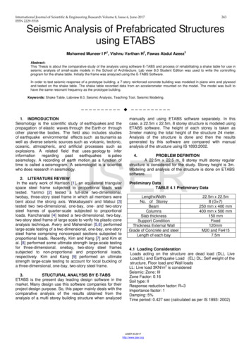
SEISMIC RX APPROACHES TO CATEGORY C INSTALLATIONSTight WallBERC2BERCBBBMainBeamTight ScrewSeismic Rx Code Compliant Solutionsand Benefits (ESR-1308)BB XXMainBeamB7/8"Tight WallTight WallTight WallBERCB XXCrossTeeBBERC2 CrossTeeB XX Meets code requirements Easy to square the system Eliminates stabilizer bars Better access to the plenum Narrow, sleek aesthetic with standard7/8" molding Suspension system can be tight on twoadjoining walls – can use the BERCor BERC2 Intermediate-duty suspension systemB7/8"3/8"7/8"3/8"2' O.C.B XClearance WallXBBB3/8" Clearance WallX Hanger WireB BERC or BERC2 ClipIBC APPROACH TO CATEGORY C INSTALLATIONSUnattached WallIBC Requirements XXX Unattached WallX 7/8" molding 3/8" clearance on all sides; 3/8" overlap of thesuspension system on the wall molding Prevents the spread of main beams/cross tees withstabilizer bars Intermediate-duty suspension system3/8"7/8"XXUnattached Wall(all four sides)2' O.C.XXStabilizer BarsXHanger WireUnattached Wall10To download CAD drawing details, go to armstrongceilings.com/seismic.For complete seismic installation requirements, contact TechLine at 1 877 276 7876.
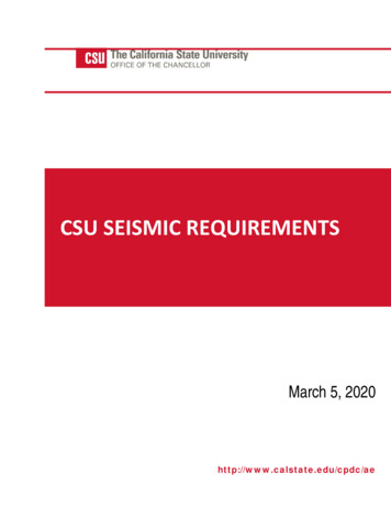
WALL-TO-WALLCSEISMICO D E R RXE Q U(ESR-1308)I RCEILINGS:EMENTSSEISMIC RX APPROACHES TO CATEGORY D, E, AND F INSTALLATIONSAttached WallAttached WallBERC2 ClipXTAC ClipBERC2 ClipPop RivetBB or PB or PB or P8" Max8" XXXXX8"8"MaxMax8"Max8" ainrunner/crossteeteeBERC2 bulbbulborwebBERC2 mainmainrunner/crossbulborwebbulborwebbulb or leMolding7/8"AngleMolding7/8"AngleMolding8" MaxUnattached WallBUnattached Wall7/8"7/8"7/8"7/8"BBBATTACHED WALLBERC2 ClipBERC2 Clip8" Max8"8"MaxMax8"Max8" MaxB8"8"MaxMax8"MaxUNATTACHED WALL2' MoldingXBBBUnattached ipBERC2 (Loose(LooseSlipScrew)Screw)Screw)ATTACHED WALLXX Hanger WireB BERC or BERC2 ClipP Pop MoldingSeismic Rx Code Compliant Solutions and Benefits (ESR-1308) arrow, sleek aesthetic with standard 7/8" moldingN Eliminates installation and aesthetic problemsassociated with 2" wall molding Lower cost solution Better access to the plenum Eliminates stabilizer bars E liminates visible pop rivets through the wall angle More profiles from which to choose Perimeter support wires within 8" Attached suspension system on two adjacent walls with theBERC2, ALBERC2, or pop rivets BERC2 or ALBERC2 clip with 3/4" clearance on unattached wallsIBC APPROACH TO CATEGORY D, E, AND F INSTALLATIONSAttached WallXXPPXXPXPXXIBC RequirementsX XXXUnattached WallX2"Attached Wall XXX3/4"X 2 " molding Attached suspension system ontwo adjacent walls with pop rivets,screws, or other means 3/4" clearance at perimeter onunattached walls and stabilizer barsto prevent the spread of main beamsand cross teesHeavy-duty suspension system2"XUnattached Wall2' O.C.XXXXXUnattached WallXX12ga. hanger wires are required onperimeter mains and tees within 8" of wallNOTE: Not required on Category C if angleis 7/8" or greaterXPHanger WirePop RivetsStabilizer Bars11
PREVENTING BORDER PANELS FROM FALLING – INSTALLATION TIPThe Case for Perimeter WiresIn full-scale seismic test evaluations for areas subject to severe seismic motion, the common cause of system failurecame from damage to cross tee end connectors (Armstrong Ceilins and competitive systems). Damage occurred in oneof two ways:Connector clip bends Base metal bendsWhen this damage occurs, it allows unbraced sections of the ceiling to move up to 3/8" at each connection. Thecumulative effect of damage at the cross tee connections may move the ceiling more than 2".Without perimeter support wires, test results demonstrate that the load of the ceiling may cause the main beams andcross tees to move beyond the 2" wall molding and drop out. System failure at the perimeter does not conform to therequirements of the code.Unsupported cross tees allow panels to drop out.Damage at cross tee connections allows ceiling movement.Braced4' O.C.Potential Movement3/4"123/8"3/8"3/8"3/8"2-1/4"
CWALL-TO-WALLO D E R E Q U I RCEILINGSEMENTSSEISMIC SEPARATION JOINTSPrevious Industry Standard With 2" Wall AnglePurpose of Separation JointsASCE 7 Section 13.5.6.2.2 mandates that ceiling areas greater than 2,500 SF must have seismic separation joints,closure angles, and horizontal restraints. This means 2" molding, perimeter spacer bars – and if the area is greaterthan 1,000 SF, lateral force bracing. It is thought that these measures will prevent the accumulated forces fromoverpowering an individual suspension system connection. This method of failure was observed after some strongCalifornia quakes in the 1980s.Pop Rivet8" Max.8" Max.2" Angle MoldingThe code does not describe how to construct the separation joint. Initially, we responded to inquiries by providingan expansion joint detail fabricated from steel moldings. This type of joint is widely accepted because it is familiar3/4"to inspectors and because the width2"2" of the separation can be set to match whatever the project designer requires.However, many designers find this method objectionable: Traditional field-fabricated expansion joint details are very noticeable on the ceiling plane56Scale: 1:8 The system is not very rigid and the suspension system can move “off module”Seismic Joint Clips for Main Beams and Cross TeesScale: 1:8Armstrong Seismic Rx Soultion (Esr-1308)Armstrong Ceilings has done full-scale testing which confirms that a ceiling fitted with o
The seismic design category must be specified by a professional engineer or registered architect on the project drawings per ASCE 7. The project requirements which include the seismic design c