Transcription
electronic controlof electricalmachines
Integral equipment forthe classroom-workshopOur in-depth knowledge of the educational world allows us to design classroomworkshops configured down to the last detail and ready to use straight nics
The flame of knowledgeFor the last 45 years Alecop has offeredtechnological material with maximum benefitswhich has led to the most important educationalorganisations opening their doors to us.HUMANITY AT WORKWe belong to the educational department ofMONDRAGON Corporación: A cooperative projectof world renown which contributes a humancomponent to the business world. A different workmethod which seeks the integral development ofpeople and respect for the chanicsbuilding
8electronic controlof electricalmachinesThe electronic motor speed regulation trainingdevices presented in this catalogue are the resultof having converted the corresponding industrialregulators into training devices, reproducingtheir construction and operating principles whileproviding major educational and functionaladvantages.
indexpageINTRODUCTION- Equipment proposal6ELECTRONIC SPEED REGULATIONOF DC SCR MOTORS-8ELECTRONIC SPEED REGULATIONOF ALTERNATING CURRENT MOTORS-10ELECTRONIC REGULATION OFBRUSHLESS MOTOR SPEED-12FAILURE PROGRAMMINGAND REPAIR SYSTEM-13ELECTRICAL MACHINES ANDBRAKING SYSTEMS-14
8Electronic control of electrical machinespage 6IntroductionEquipmentproposalThe electronic motor speed regulation training devices presented in this catalogueare the result of having converted the corresponding industrial regulators into trainingdevices, reproducing their construction and operating principles while providingmajor educational and functional advantages.Basic content thatcan be workedon using thisequipment:Block diagram representation of control systems.Speed control in both rotation directions.Four-quadrant operation.Operation at constant torque and power.Current and speed regulation, types of feedback and correctors.Speed regulation, P and PI correctors.Torque and speed regulation. Feedback loops and correctors.Torque regulation: detection of rotor position and set point generation.Dissipative braking: crowbar circuit.Analytic corrector tuning in accordance with the symmetric optimum criterion.Adjustment and tuning techniques.Asynchronous motor speed variation. Voltage/frequency ratio.Failure diagnosis and repair.Functions- Panel support, for use in either vertical position (frame)or table-mounted.- Wireless equipment configuration.- Power and control circuit symbols printed according tothe IEC (International Electronic Commission) Europeanstandards.- Test points in 2 mm sockets for control signalmeasurement.- External set points may be worked with, to enableactuation from an automaton or other control element.- Motor operating conditions (voltage, current, speed,etc.) can be viewed on a display on the panel, with noneed for additional instruments.- One single supply for all the equipment.SafetyBoth the control panels and the electricalmachines have safety terminals at voltagepoints exceeding 30 V, in compliance withthe European Low Voltage Directive.FailuresThe training devices enable studentsto develop failure diagnosis and repairskills: they can analyse and diagnose thefailures and repair them virtually.
Electronic control of electrical machinesIntroductionELECTROTECHNICAL POWER SYSTEMSRMCC-900DC motor speedregulationRMCA-900AC motor speedregulationRMBR-900Brushless motor speedregulationBack-up resourcesThis equipment includes a set of back-up elements to aid thetrainer, e.g.: User Manual, containing the instructions for startup and operation of the equipment, its technicalcharacteristics and detailed information on the failurerepair system. Practical Manual, describing goals, teaching sequenceand solutions for each of the practical activities. Theory Manual.page 78
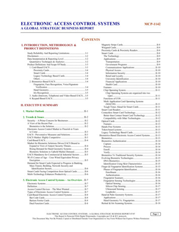
Electronic control of electrical machines8page 8 Electronic speed regulation of DC SCR motorsElectronic speed regulationof DC SCR motorsEquipment designed for studying the functioning, adjustment and repair ofthe speed regulation systems of DC motors, based on double thyristor bridgetechnology, and the different associated control options.The following basic content may be worked on: Block diagram representation of control systems. Current and speed regulation, types of feedback and correctors. Four-quadrant operation. Constant torque and power operation. Adjustment and tuning techniques. Failure diagnosis and repair.Didactic DC engine regulation unitRMCC-900A multi-panel system which enablesdifferent types of controls to be set up. Ithas six panels, each with unit diagramsprinted on it, which are automaticallyrecognised by the equipment when theyare fixed in place. This allows for thefollowing setups: Torque regulator in a single quadrant.One-way speed regulator, with feedback via tachodynamo.Speed regulator with feedback via f.c.e.m.One-way speed regulator, with operation at a constant torque and power.Four quadrant torque regulation.Speed regulator in both spin directions, with regenerative braking. The board controls allow selection of theworking mode of the controller and adjusting the system parameters:Slogans external, internal, manual, ramps, .Parameters of the different weightings.Limitations of current and speed.Etc.The panel incorporates two LCD displays which enables the speed and current to be displayed, as well as indicatorlights for the functioning quadrant of the motor.
Electronic control of electrical machinesElectronic speed regulation of DC SCR motors page 9The unit is equipped with a set of protection devicesand alarms to facilitate analysis of any occurrence,guaranteeing total safety: Phase loss. Incorrect phase sequence. Control supply failure. Excitation current loss. Maximum current limitation. Open armature circuit. I2 x t protection.Accessories supplied: User’s manual and practical activities.NECESSARY elements which are not supplied: AL-506 or 1006 motor (page 14). Braking system (page 15).Optional elements: Failure programming console (page 13). Theory Manual. Data collection and display system. 380-220 Triphasic autotransformer.TECHNICAL ree-phase 230 V- 50/60 HzArmature output0 to 230 V- 3 AExcitation output0 to 230 V- 0,6 APower0,6 KWRegulation range at constant torque0 to 1500 r.p.m.Regulation range at constant power0 to 3000 r.p.m.Didactic transformer 380-220AT-3822triphasicAn autotransformer for various applications in whichit is necessary to have a 220 V triphasic voltage, withthe following characteristics: Supply: triphasic 380 V - 50 Hz. Output: triphasic 220 V - 50 Hz. Power: 1 KVA. Output available as safety terminals and powerpoints. Pilot lights indicating presence of phases. Fused protection in each phase.8
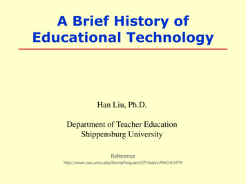
8Electronic control of electrical machinespage 10 Electronic speed regulation of alternating current motorsElectronic speed regulationof alternating current motorsEquipment designed for studying the functioning, adjustment and repair ofasynchronous motor speed regulation systems, based on frequency convertertechnology.The following basic content may be worked on: Block diagram representation of control systems. Asynchronous motor speed variation. Voltage/frequency ratio. Dissipative braking: crowbar circuit. Speed control in both rotation directions: four-quadrant operation. Operation at constant torque and power. Adjustment and tuning techniques. Failure diagnosis and repair.Didactic AC engine regulation unitRMCA-900The panel incorporates a frequency converter designed to supply an asynchronous motor of up to 1 kWpower. It consists of a triphasic invertor based on IGBTs and all of the circuitry necessary for their control.It enables a triphasic output voltage, variable in amplitude and frequency, to be obtained, by means of thePWM modulation. The frequency may be increased to double the nominal frequency in the constant powermode, which enables a control to be obtained above and beyond the nominal speed of the motor. Sine ortrapezoidal PWM modulation can be selected.
Electronic control of electrical machinesElectronic speed regulation of alternating current motors page 11The controls incorporated enable the work mode of theconverter to be selected, as well as the parameters ofthe system to be adjusted:Accessories supplied: User’s manual and practical activities.NECESSARY elements which are not supplied: AL-1106/06 motor (page 14). Tachodynamo (page 15). Braking system (page 15). External, internal, manual commands, ramps. Parameters at constant torque and power. Low speed torque compensation. Etc.The effective voltage and frequency may be displayedalternately on the panels LCD display, and additionallythere are lights indicating the quadrant of thefunctioning of the motor and the activation of energydevolution system (braking).Optional elements: Failure programming console (page 13). Theory Manual. Data collection and display system.The unit is equipped with a set of protection devicesand alarms to facilitate analysis of any occurrence,guaranteeing total safety: Maximum current. Maximum temperature. Maximum bus voltage. Minimum bus voltage. Control supply failure. I2 x t protection.TECHNICAL ngle-phase 230 V- 50/60 HzOutput voltageThree-phase 0 to 220 VOutput frequency at constant torque0 to 50 Hz or 0 to 60 HzRegulation range at constant power0 to 100 Hz or 0 to 120 HzPower1 KW8
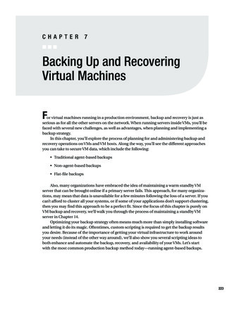
8Electronic control of electrical machinespage 12 Electronic regulation of Brushless motor speedElectronic regulationof Brushless motor speedEquipment designed for studying the functioning, adjustment and repair of AC brushlessmotor speed regulation.The following basic content may be worked with: Block diagram representation of control systems. Torque regulation: detection of rotor position and set point generation. Speed regulation, P and PI correctors. Dissipative braking: the crowbar circuit. Adjustment and tuning techniques. Failure diagnosis and repair.Didactic Brushless engineregulation unitRMBR-900The power circuit is made up of a rectifier bridge, a filtercondenser and a triphasic invertor based on IGBTs.In addition to this, it incorporates a crowbar circuit forprotecting the equipment when the voltage in the busincreases through braking energy devolution.The controls incorporated enable the function mode ofthe converter to be selected, in addition to enabling theparameters of the system to be adjusted: External, internal, manual commands, ramps,. Corrector parameters. Regulation in current or in speed. Limitation of maximum speed.The speed and current may be displayed on thepanel s LCD display, and additionally there are lightsindicating the quadrant of the functioning of themotor and the activation of energy devolution system(braking).The unit is equipped with a set of protection devicesand alarms to facilitate analysis of any occurrence,guaranteeing total safety: Maximum current. Maximum temperature. Maximum bus voltage. Minimum bus voltage. Control supply failure. I2 x t protection.Accessories supplied: User’s manual and practical activities.NECESSARY elements which are not supplied: Brushless motor (page 14). Braking system (page 14).Optional elements: Failure programming console (page 13). Data collection and display system.TECHNICAL CHARACTERISTICS RMBR-900Reference9EQRMBR900SupplySingle-phase 230 V- 50/60 HzOutput voltage0 to 196 VOutput frequency0 to 200 HzPower1 KW
Electronic control of electrical machinesElectronic regulation of Brushless motor speed page 13Failure programmingand repair systemThe RMCC, RMCA and RMBR-900 regulation panels havea system for failure diagnosis and virtual repair, based ona micro processor in the panel which communicates withthe user via a failure programming console with a 4 x 24character LCD display and a 21-key membrane keyboard.An electronic key, inserted in a slot in the panel, allowsaccess to the trainer menu to change the codes thatgenerate the failures.UNITNº OF FAILURESPROGRAMMABLENº OF FAILURESPROGRAMMABLERMCC-90031Set point failures, tacho dynamo failures,thyristor triggering failures, etc.RMCA-90014Set point failures, rotation reversal failures,crowbar failure, etc.RMBR-90026Set point failures, corrector failure, failure in theencoder processing circuit, etc.8
8Electronic control of electrical machinespage 14 Electrical machines and braking systemsElectrical machinesand braking systemsAll the electrical machines are mounted on an aluminium bedplate, with theircorresponding end connections for quick, easy coupling to other machines, brakes ortacho dynamos. They also include a printed terminal block with safety terminals andprotection guards on the shafts.DC training motorAL-506 / AL-1006Model AL-506 is an independent excitation motor.Model AL-1006 is an compound excitation machine.CHARACTERISTICSReferencePowerNominal voltageNominal speedShaft 1006ZC370W220V2500rpm80Three-phase asynchronous trainingmotor AL-1106Single-speed three-phase asynchronous squirrel-cagemotor (50Hz/60Hz).CHARACTERISTICS 50HzReferencePowerNominal voltageNominal speedShaft TERISTICS 60HzReferencePowerNominal voltageNominal speedShaft heightAL-11069MAK1106HC400W230/400V1690rpm80
Electronic control of electrical machinesElectrical machines and braking systems page 15Asynchronous didactic motorBRUSHLESS ACCHARACTERISTICSReferenceF.c.e.m.Nominal intensityNominal torqueMaximum speedEncoderShaft heightAL-BRU80MTRALBRU80150 V4A2,5 Nm4000 r.p.m.2000 impulses/turn80 mmAC Servomotor, associated to the corresponding regulator, it behaves as a high prestation’s DC motor (
Electronic control of electrical machines 8 Introduction page 7 Both the control panels and the electrical machines have safety terminals at voltage points exceeding 30 V, in compliance with the European Low Voltage Directive. - Panel support, for use in either vertical position (frame) or table-mounted. - Wireless equipment configuration.