Transcription
Cisco Connected Grid Ethernet SwitchModule Interface Card Getting StartedGuideFirst Published: May 2012Last Updated: January 2014Part Number: OL-23421-02Cisco Systems, Inc.www.cisco.comCisco has more than 200 offices worldwide.Addresses, phone numbers, and fax numbersare listed on the Cisco website atwww.cisco.com/go/offices.Text Part Number: OL-23421-02
THE SPECIFICATIONS AND INFORMATION REGARDING THE PRODUCTS IN THIS MANUAL ARE SUBJECT TO CHANGE WITHOUT NOTICE. ALLSTATEMENTS, INFORMATION, AND RECOMMENDATIONS IN THIS MANUAL ARE BELIEVED TO BE ACCURATE BUT ARE PRESENTED WITHOUTWARRANTY OF ANY KIND, EXPRESS OR IMPLIED. USERS MUST TAKE FULL RESPONSIBILITY FOR THEIR APPLICATION OF ANY PRODUCTS.THE SOFTWARE LICENSE AND LIMITED WARRANTY FOR THE ACCOMPANYING PRODUCT ARE SET FORTH IN THE INFORMATION PACKET THATSHIPPED WITH THE PRODUCT AND ARE INCORPORATED HEREIN BY THIS REFERENCE. IF YOU ARE UNABLE TO LOCATE THE SOFTWARE LICENSEOR LIMITED WARRANTY, CONTACT YOUR CISCO REPRESENTATIVE FOR A COPY.The Cisco implementation of TCP header compression is an adaptation of a program developed by the University of California, Berkeley (UCB) as part of UCB’s publicdomain version of the UNIX operating system. All rights reserved. Copyright 1981, Regents of the University of California.NOTWITHSTANDING ANY OTHER WARRANTY HEREIN, ALL DOCUMENT FILES AND SOFTWARE OF THESE SUPPLIERS ARE PROVIDED “AS IS” WITHALL FAULTS. CISCO AND THE ABOVE-NAMED SUPPLIERS DISCLAIM ALL WARRANTIES, EXPRESSED OR IMPLIED, INCLUDING, WITHOUTLIMITATION, THOSE OF MERCHANTABILITY, FITNESS FOR A PARTICULAR PURPOSE AND NONINFRINGEMENT OR ARISING FROM A COURSE OFDEALING, USAGE, OR TRADE PRACTICE.IN NO EVENT SHALL CISCO OR ITS SUPPLIERS BE LIABLE FOR ANY INDIRECT, SPECIAL, CONSEQUENTIAL, OR INCIDENTAL DAMAGES, INCLUDING,WITHOUT LIMITATION, LOST PROFITS OR LOSS OR DAMAGE TO DATA ARISING OUT OF THE USE OR INABILITY TO USE THIS MANUAL, EVEN IF CISCOOR ITS SUPPLIERS HAVE BEEN ADVISED OF THE POSSIBILITY OF SUCH DAMAGES.CCDE, CCENT, Cisco Eos, Cisco HealthPresence, the Cisco logo, Cisco Lumin, Cisco Nexus, Cisco StadiumVision, Cisco TelePresence, Cisco WebEx, DCE, and Welcometo the Human Network are trademarks; Changing the Way We Work, Live, Play, and Learn and Cisco Store are service marks; and Access Registrar, Aironet, AsyncOS,Bringing the Meeting To You, Catalyst, CCDA, CCDP, CCIE, CCIP, CCNA, CCNP, CCSP, CCVP, Cisco, the Cisco Certified Internetwork Expert logo, Cisco IOS,Cisco Press, Cisco Systems, Cisco Systems Capital, the Cisco Systems logo, Cisco Unity, Collaboration Without Limitation, EtherFast, EtherSwitch, Event Center, Fast Step,Follow Me Browsing, FormShare, GigaDrive, HomeLink, Internet Quotient, IOS, iPhone, iQuick Study, IronPort, the IronPort logo, LightStream, Linksys, MediaTone,MeetingPlace, MeetingPlace Chime Sound, MGX, Networkers, Networking Academy, Network Registrar, PCNow, PIX, PowerPanels, ProConnect, ScriptShare, SenderBase,SMARTnet, Spectrum Expert, StackWise, The Fastest Way to Increase Your Internet Quotient, TransPath, WebEx, and the WebEx logo are registered trademarks ofCisco Systems, Inc. and/or its affiliates in the United States and certain other countries.Cisco and the Cisco logo are trademarks or registered trademarks of Cisco and/or its affiliates in the U.S. and other countries. To view a list of Cisco trademarks, go to thisURL: www.cisco.com/go/trademarks. Third-party trademarks mentioned are the property of their respective owners. The use of the word partner does not imply a partnershiprelationship between Cisco and any other company. (1110R)No combinations are authorized or intended under this document.Any Internet Protocol (IP) addresses used in this document are not intended to be actual addresses. Any examples, command display output, and figures included in thedocument are shown for illustrative purposes only. Any use of actual IP addresses in illustrative content is unintentional and coincidental. 2012–2014 Cisco Systems, Inc. All rights reserved.
CONTENTSPrefaceiiiPurposeiiiDocument ConventionsRelated PublicationsiiiivObtaining Documentation and Submitting a Service RequestCHAPTER1Product Overview1-1Switch Models1-1ivPorts 1-2Port Locations 1-2Port Labeling 1-310/100BASE-T Ports 1-4PoE and PoE Ports 1-410/100 Mb/s SFP Module Slots 1-5100/1000 Mb/s SFP Module Slots 1-5Dual-Purpose Gigabit Ethernet Ports 1-5Supported SFPs 1-6LEDs1-7Router Compact Flash Memory CardsCHAPTER2Installation1-92-1Pre-Installation 2-1Installation Warning StatementsInstallation2-12-2Connecting to the Network 2-5Connecting the Copper Switch Module 2-5Connecting the Fiber Switch Module 2-6Removing the Switch ModuleCHAPTER3Express Setup3-1System RequirementsExpress Setup2-73-13-1Cisco Connected Grid Ethernet Switch Module Interface Card Getting Started GuideOL-23421-021
ContentsTroubleshooting Express SetupCHAPTER43-5Resetting the Switch Module3-5Managing the Switch Module4-1Using the Device Manager4-1Cisco Configuration ProfessionalOther Management Options4-14-2Accessing the Switch Module 4-2Disconnecting from the Switch Module4-3Connecting Devices to the Switch Module 4-410/100BASE-T Ports 4-4SFP Module Slots 4-5Dual-Purpose Port with RJ-45 and SFP ConnectorsVerifying Port Connectivity 4-9APPENDIXACable and Connectors4-7A-1Connector Specifications A-110/100BASE-T Ports A-1SFP Module Connectors A-1Dual-Purpose Ports A-2Cables and Adapters A-2SFP Module Cables A-2Cable Pinouts A-4Cisco Connected Grid Ethernet Switch Module Interface Card Getting Started Guide2OL-23421-02
PrefacePurposeThis guide describes the hardware features of the Cisco Connected Grid Ethernet Switch ModuleInterface Card (switch module). It describes how to install the switch module in the Cisco 2010Connected Grid Router, and how to configure it.This guide also describes how to: Access the switch module from the host router Connect devices to the switch module ports Manage the switch module Perform Express Setup troubleshootingDocument ConventionsNoteCautionMeans reader take note. Notes contain helpful suggestions or references to materials not contained inthis manual.Means reader be careful. In this situation, you might do something that could result in equipmentdamage or loss of data.Cisco Connected Grid Ethernet Switch Module Interface Card Getting Started GuideOL-23421-02iii
WarningIMPORTANT SAFETY INSTRUCTIONSThis warning symbol means danger. You are in a situation that could cause bodily injury. Before youwork on any equipment, be aware of the hazards involved with electrical circuitry and be familiarwith standard practices for preventing accidents. Use the statement number provided at the end ofeach warning to locate its translation in the translated safety warnings that accompanied thisdevice. Statement 1071SAVE THESE INSTRUCTIONSRelated PublicationsNoteBefore installing, configuring, or upgrading the switch, see the release notes on Cisco.com for the latestinformation. Release Notes for Cisco 2520 Connected Grid Switch and Ethernet Switch Module Cisco Connected Grid Ethernet Switch Module Interface Card Software Configuration Guide Regulatory Compliance and Safety Information for Cisco Connected Grid Router 2000 SeriesRouters Cisco Connected Grid Modules ps10984/tsd products support series home.html Cisco 2000 Series Connected Grid Routers ps10977/tsd products support series home.html Cisco SFP odules/ps5455/prod installation guides list.htmlObtaining Documentation and Submitting a Service RequestFor information on obtaining documentation, submitting a service request, and gathering additionalinformation, see the monthly What’s New in Cisco Product Documentation, which also lists all new andrevised Cisco technical documentation, w/whatsnew.htmlSubscribe to the What’s New in Cisco Product Documentation as a Really Simple Syndication (RSS) feedand set content to be delivered directly to your desktop using a reader application. The RSS feeds are a freeservice and Cisco currently supports RSS version 2.0.Cisco Connected Grid Ethernet Switch Module Interface Card Getting Started GuideivOL-23421-02
CH A P T E R1Product OverviewThis chapter describes the Cisco Connected Grid Ethernet Switch Module Interface Card, hereafterreferred to as the switch module. The switch deployed together with the Cisco 2010 Connected GridRouter (CGR 2010) offers utilities a rugged networking solution to enable reliable and secure two-waycommunication for substation automation.NoteThe Cisco CGR 2010 router must be running Cisco IOS Release 15.1(4)M or higher to run the switchmodule. Switch Models, page 1-1 Ports, page 1-2 LEDs, page 1-7 Router Compact Flash Memory Cards, page 1-9Switch ModelsTable 1-1Connected Grid Ethernet Switch Module Interface Card ModelsModeDescriptionGRWIC-D-ES-6S (SFP fibermodel)4 100 Mb/s SFP (small form-factor pluggable) module slots,1 Gigabit Ethernet (GE) dual-purpose port (1 10/100/1000BASE-Tport and 1 100/1000 Mb/s SFP module slot), 1 100/1000 M/bs SFPmodule slot.GRWIC-D-ES-2S-8PC(Copper model)8 10/100BASE-T ports, 1 GE dual-purpose port(1 10/100/1000BASE-T port and 1 100/1000 Mb/s SFP module slot),1 100/1000 Mb/s SFP module slot.NoteThe first four 10/100BASE-T ports (FE0/1, FE0/2, FE0/3,FE0/4) are PoE 1 ports.1. PoE Power over Ethernet plus (provides up to 30 W per port).Cisco Connected Grid Ethernet Switch Module Interface Card Getting Started GuideOL-23421-021-1
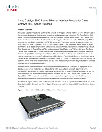
Chapter 1Product OverviewPortsPorts Port Locations, page 1-2 Port Labeling, page 1-3 10/100BASE-T Ports, page 1-4 PoE and PoE Ports, page 1-4 10/100 Mb/s SFP Module Slots, page 1-5 100/1000 Mb/s SFP Module Slots, page 1-5 Dual-Purpose Gigabit Ethernet Ports, page 1-5 Supported SFPs, page 1-6Port LocationsFigure 1-1GRWIC-D-ES-6S (SFP Fiber Model)21110/100 Mb/s SFP module slots2Dual-purpose port3100/1000 Mb/s SFP module slot23905153Cisco Connected Grid Ethernet Switch Module Interface Card Getting Started Guide1-2OL-23421-02
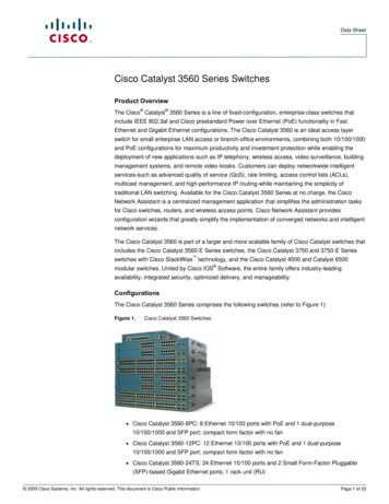
Chapter 1Product OverviewPortsFigure 1-2GRWIC-D-ES-2S-8PC (Copper Model)221110/100BASET-T ports2Dual-purpose port3100/1000 Mb/s SFP Port3905143Port LabelingThe port labeling for the switch modules is described in Table 1-2 and Table 1-3.Table 1-2GRWIC-D-ES-6S Port LabelingPortLabel4 10/100 Mb/s SFP module slotsFE0/1, FE0/2, FE0/3, FE0/4Dual-purpose port (10/100/1000BASE-T port and GE0/1100/1000 Mb/s SFP module slot)100/1000 Mb/s SFP module slotGE0/2Cisco Connected Grid Ethernet Switch Module Interface Card Getting Started GuideOL-23421-021-3
Chapter 1Product OverviewPortsTable 1-3GRWIC-D-ES-2S-8PC Port LabelingPortDescription8 10/100BASE-T portsFE0/1, FE0/2, FE0/3, FE0/4, FE0/5, FE0/6,FE0/7, FE0/8Dual-purpose port (10/100/1000BASE-T port and GE0/1100/1000 Mb/s SFP module slot)100/1000 Mb/s SFP module slotGE0/210/100BASE-T PortsYou can set the 10/100BASE-T ports on the switch to operate in any combination of half duplex, fullduplex, or 10 or 100 Mb/s. You can set the ports for speed and duplex auto-negotiation. The defaultsetting is auto-negotiate.When set for auto-negotiation, the switch determines the speed and duplex settings of the attacheddevice, and advertises its own capabilities. If the connected device also supports auto-negotiation, theswitch negotiates the best connection (the fastest line speed that both devices support and full-duplextransmission if the attached device supports it), and configures itself accordingly. In all cases, theattached device must be within 328 feet (100 meters).The 10/100BASE-T ports use RJ-45 connectors with Ethernet pinouts. The maximum cable length is 328feet (100 meters). The 100BASE-TX traffic requires Category 5, Category 5e, or Category 6 unshieldedtwisted pair (UTP) cable. The 10BASE-T traffic can use Category 3 or Category 4 UTP cable.NoteOn the GRWIC-D-ES-2S-8PC switch module, the first four 10/100 Fast Ethernet ports (FE0/1, FE0/2,FE0/3, FE0/4) are PoE ports.PoE and PoE PortsThe first four 10/100 Fast Ethernet ports (FE0/1, FE0/2, FE0/3, FE0/4) on the GRWIC-D-ES-2S-8PCswitch module are PoE ports.WarningVoltages that present a shock hazard may exist on Power over Ethernet (PoE) circuits ifinterconnections are made using uninsulated exposed metal contacts, conductors, or terminals.Avoid using such interconnection methods, unless the exposed metal parts are located within arestricted access location and users and service people who are authorized within the restrictedaccess location are made aware of the hazard. A restricted access area can be accessed only throughthe use of a special tool, lock and key or other means of security. Statement 1072These PoE ports provide: Support for IEEE 802.3af-compliant powered devices (up to 15.4 W PoE per port) and support forIEEE 802.3at-compliant powered devices (up to 30 W PoE per port). Support for prestandard Cisco powered devices. Configurable support for Cisco intelligent power management, including:– enhanced power negotiationCisco Connected Grid Ethernet Switch Module Interface Card Getting Started Guide1-4OL-23421-02
Chapter 1Product OverviewPorts– power reservation– per-port power policingOn the GRWIC-D-ES-2S-8PC model (Copper model), the first four 10/100BASE-T ports (FE0/1,FE0/2, FE0/3, FE0/4) are PoE ports. A maximum of two PoE ports or four PoE ports can besupported at one time.For information about configuring and monitoring PoE/PoE ports, see the “Interface Configuration”chapter of the Cisco Connected Grid Ethernet Switch Module Interface Card Software ConfigurationGuide on Cisco.com.For information about port connections and port specifications, see the “Connecting Devices to theSwitch Module” section on page 4-4 and the “Cable and Connectors” appendix.NoteThe output of the PoE circuit has been evaluated as a Limited Power Source (LPS) per IEC 60950-1.10/100 Mb/s SFP Module SlotsThe IEEE 802.3u 100 Mb/s SFP module slots provide full-duplex 100 Mb/s connectivity overmulti-mode (MM) fiber cables or single-mode (SM) fiber cables. These ports use a SFP fiber-optictransceiver module that accepts a dual LC connector. Check the SFP specifications for the cable type andlength.100/1000 Mb/s SFP Module SlotsThe IEEE 802.3u 1000 Mb/s SFP module slots provide full-duplex 100 or 1000 Mb/s connectivity overmulti-mode (MM) fiber cables or single-mode (SM) fiber cables. These ports use a SFP fiber-optictransceiver module that accepts a dual LC connector. Check the SFP specifications for the cable type andlength.Dual-Purpose Gigabit Ethernet PortsYou can configure the dual-purpose ports on the switch as either 10/100/1000 Ethernet ports or as SFPmodule ports. You can set the 10/100/1000 Ethernet ports to autonegotiate, or you can configure themas fixed 10, 100, or 1000 Mb/s Ethernet ports.By default, the switch selects the medium for each dual-purpose port (10/100/1000BASE-T or SFP).When a link is achieved on one media type, the switch disables the other media type until the active linkgoes down. If links are active on both media, the SFP module port has priority, but you can use themedia-type interface configuration command to manually designate the port as an RJ-45 port or an SFPport.You can configure the speed and duplex settings consistent with the selected media type. For informationon configuring interfaces, see the “Interface Configuration” chapter of the Cisco Connected GridEthernet Switch Module Interface Card Software Configuration Guide on Cisco.com.For more information on the SFP module ports see the “Supported SFPs” section on page 1-6 and theinformation on the SFP modules connectors and cables in the “Cable and Connectors” appendix.Cisco Connected Grid Ethernet Switch Module Interface Card Getting Started GuideOL-23421-021-5
Chapter 1Product OverviewPortsSupported SFPsTable 1-4 describes the supported SFP modules.NoteThe following SFP module slot points should be noted:- The four 100 Mb/s FE SFP module slots of the Fiber model can only support 100FX connections.- The 100/1000 Mb/s SFP module slots support both 100FX and 1000Base-X connections.Table 1-4Supported SFP ModelsType of SFP ModuleNoteModelRugged and Industrial SFPs GLC-SX-MM-RGD-40 to 140 F (-40 to 60 C) GLC-LX-SM-RGD GLC-ZX-SM-RGD GLC-FE-100LX-RGD GLC-FE-100FX-RGDCommercial SFPs GLC-BX-U with digital optical monitoring (DOM) support32 to 113 F (0 to 45 C) GLC-BX-D with DOM support GLC-FE-100LX GLC-FE-100BX-D GLC-FE-100BX-U GLC-FE-100FX GLC-FE-100EX GLC-FE-100ZX CWDM-SFP with DOM supportExtended temperature SFPs SFP-GE-S with DOM support23 to 140 F (-5 to 60 C) SFP-GE-L with DOM support SFP-GE-Z with DOM support GLC-EX-SMD with DOM supportSFP module GLC-FE-100FX-RGD requires Version 2 to operate correctly in the switch module. Afterinstalling this SFP, you may receive the following message:PLATFORM-4-SFP REVISION WARNING: Interface interface has an obsolete SFP module that isnot recommended for this product.This is a software warning that occurs when detecting an older version of SFP moduleGLC-FE-100FX-RGD, which has been replaced with an updated version (Rev. 2).The recommended action is to replace this SFP module with the latest Cisco certified version of this SFP.The switch module requires Rev. 2 or higher of this SFP for optimum operation over the entire operatingtemperature range. To check the VID for the revision number, use the show inventory command.Cisco Connected Grid Ethernet Switch Module Interface Card Getting Started Guide1-6OL-23421-02
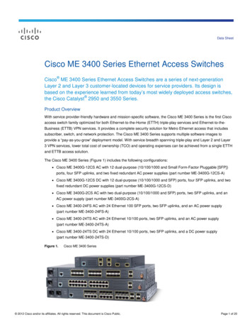
Chapter 1Product OverviewLEDsLEDsThis section describes the location and function of the LEDs on the switch module.GRWIC-D-ES-6S Switch Module (SFP Fiber Model) LEDs237968Figure 1-3Table 1-5GRWIC-D-ES-6S Switch Module (SFP Fiber Model) LED DescriptionsLEDDescriptionSYSIndicates the status of the switch module. If the LED is yellow, check the Syslog forissues.FE0/1 toFE 0/4Indicates the state of the 100 Mb/s SFP module slots: LED is flashing green—data transmission is taking place. LED is off—the link is down. LED is solid yellow—the port is in an error state (disabled).Cisco Connected Grid Ethernet Switch Module Interface Card Getting Started GuideOL-23421-021-7
Chapter 1Product OverviewLEDsTable 1-5GRWIC-D-ES-6S Switch Module (SFP Fiber Model) LED Descriptions (continued)LEDDescriptionGE0/1Indicates the state of the Gigabit Ethernet dual purpose port:GE0/2LED is flashing green—data transmission is taking place. LED is off—the port is down. LED is solid yellow—the port is in an error state (disabled).Indicates the state of the 1000 Mb/s SFP module slot: LED is flashing green—data transmission is taking place. LED is off—the port is down. LED is solid yellow—the port is in an error state (disabled).GRWIC-D-ES-2S-8PC Switch Module (Copper Model) LEDs237966Figure 1-4 Table 1-6GRWIC-D-ES-2S-8PC Switch Module (Copper Model) LED DescriptionsLEDDescriptionPoEIndicates if PoE/PoE is functioning.The four PoE-capable ports are FE0/1, FE0/2,FE0/3, and FE0/4.SYSIndicates the status of the switch module. If the LED is yellow, check the Syslog forissues.Cisco Connected Grid Ethernet Switch Module Interface Card Getting Started Guide1-8OL-23421-02
Chapter 1Product OverviewRouter Compact Flash Memory CardsTable 1-6GRWIC-D-ES-2S-8PC Switch Module (Copper Model) LED Descriptions (continued)LEDDescriptionFE0/1 toFE 0/8Indicates state of the Fast Ethernet ports:GE0/1GE0/2 LED is flashing green—data transmission is taking place. LED is off—the link is down. LED is solid yellow—the port is in an error state (disabled).Indicates the state of the Gigabit Ethernet dual purpose port: LED is flashing green—data transmission is taking place. LED is off—the port is down. LED is solid yellow—the port is in an error state (disabled).Indicates the state of the 1000 Mb/s SFP module slot: LED is flashing green—data transmission is taking place. LED is off—the port is down. LED is solid yellow—the port is in an error state (disabled).Router Compact Flash Memory CardsCompact flash cards can help you configure new or replacement routers, and to recover the configurationof a failed router. For example, if the Connected Grid Swap Drive feature is enabled, you can transferthe same system configuration information from one router to another by using a compact flash memorycard (or compact flash card) while the routers are operating. This is done by inserting an optionalcompact flash card in slot CF1 and copying all contents of CF0. After the copy operation is completed,you can remove and insert this compact flash card unit in slot CF0 of either a new router or a replacementrouter for a failed unit. When the new or replacement router is rebooted, it uses the configuration fromthe compact flash card as the running and startup configuration. This functionality enables you toquickly configure new or replacement routers with a standard configuration with little or no manualconfiguration required.Cisco Connected Grid Ethernet Switch Module Interface Card Getting Started GuideOL-23421-021-9
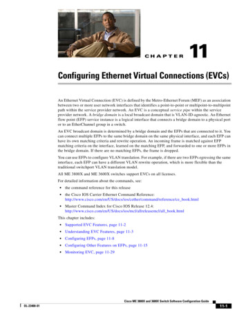
Chapter 1Product OverviewRouter Compact Flash Memory CardsFor more information on the Swap Drive feature, tedgrid/cgr2010/software/15 2 2 t/cgr2010 15 2 2t swcg.html#wp2039791The router supports a maximum of two compact flash memory cards. The router ships with one compactflash card installed in Slot CF0 and supports a second, optional flash card that you can order with therouter or supply separately.Figure 5 illustrates the location of the compact flash card slots on the router.Cisco Connected Grid 2010 Router—Compact Flash Memory Card Slot LocationsPSU OKPSU1ACTSFP SFP GE GE0/1 0/0 0/1 0/0EN EN LINK LINKPSU2SLOT3PWR-150W-HVCF0PWR-150W-HVPSU OKCF11USBCONCF1CAUTION: This unit may have more thanone power source. Disconnect all powersources before servicing to avoidelectric shock.SYS SPD SPD SPD SPD20CONSOLEPS TypeInput Rating Per Sources10ALoV dc24-60V2AHiV dc100-270V2AV ac, 50/60 Hz 100-240V PSU21CF0DO NOT REMOVE DURINGNETWORK OPERATIONDO NOT REMOVE DURINGNETWORK OPERATIONCisco Connected Grid Router 2000 Series1284213Figure 52ItemLabel onRouter1CF1This slot supports an optional compact flash card that you can flash1:order with the router or supply separately. The Connected GridSwap Drive feature is not supported on this slot.2CF0This is the required slot for use with the Connected Grid Swap flash orflash0:Drive feature. The router comes with a compact flash cardalready installed in this slot.DescriptionCisco IOSInterface NameThe Connected Grid Swap Drive feature is supported on thisCF slot only.For additional information about the router compact flash memory support, refer to the router hardwareinstallation guide d installation guides list.htmlCisco Connected Grid Ethernet Switch Module Interface Card Getting Started Guide1-10OL-23421-02
CH A P T E R2InstallationThis section describes how to install the switch module in Cisco CGR 2010 routers. The switch moduleoccupies two of four slots on the I/O side of the router. This chapter includes the following topics: Pre-Installation Installation Connecting to the Network Removing the Switch ModulePre-InstallationBefore installing the switch module, verify these guidelines are met: Clearance to the I/O-side view is such that the LEDs can be easily read Cabling is away from sources of electrical noise, such as radios, power lines, and fluorescentlighting fixtures. Make sure that the cabling is away from other devices that might damage thecables. Airflow around the switch module and through the vents is unrestricted Temperature around the unit does not exceed 140 F (60 C). If the switch module is installed in aclosed or multirack assembly, the temperature around it might be higher than normal roomtemperature. Relative humidity around the switch module does not exceed 95 percent (noncondensing) Altitude at the installation site is not higher than 10,000 feet For 10/100 and 10/100/1000 fixed ports, cable lengths from the switch module to connected devicesare not longer than 328 feet (100 meters)Installation Warning StatementsThis section includes the basic installation warning statements. Translations of these warning statementsappear in the Regulatory Compliance and Safety Information for the Cisco CGS 2520 Switches and theRegulatory Compliance and Safety Information for Cisco Connected Grid Router 2000 Series Routersdocuments.Cisco Connected Grid Ethernet Switch Module Interface Card Getting Started GuideOL-23421-022-1
Chapter 2InstallationInstallationWarningThis unit is intended for installation in restricted access areas. A restricted access area can beaccessed only through the use of a special tool, lock and key, or other means of security.Statement 1017WarningOnly trained and qualified personnel should be allowed to install, replace, or service this equipment.Statement 1030WarningTo prevent the system from overheating, do not operate it in an area that exceeds the maximumrecommended ambient temperature of:140 F (60 C) Statement 1047WarningThis equipment is supplied as “open type” equipment. It must be mounted within an enclosure that issuitably designed for those specific environmental conditions that will be present and appropriatelydesigned to prevent personal injury resulting from accessibility to live parts. The interior of theenclosure must be accessible only by the use of a tool.The enclosure must meet IP 54 or NEMA type 4 minimum enclosure rating standards. Statement 1063WarningThis equipment is intended to be grounded to comply with emission and immunity requirements.Ensure that the switch functional ground lug is connected to earth ground during normal use.Statement 1064WarningTo prevent airflow restriction, allow clearance around the ventilation openings to be at least: 1.75 in.(4.4 cm) Statement 1076InstallationFollow these steps to install the switch module:Step 1Before you install (or remove) the switch module from the host CGR 2010 router, you must power downthe router as described in the “Shutting Off Power” section in Chapter 3 of the Cisco Connected GridRouter 2010 Hardware Installation Guide.Step 2Facing the I/O side of the Cisco CGR 2010 router, use a no. 2 Phillips screwdriver to remove the slotdivider between the slots where you intend to install the switch module - either slots 0 and 1 or slots 2and 3 (see Figure 2-1).a.Remove the two screws on the slot divider.b.Remove the slot divider and set it aside.Cisco Connected Grid Ethernet Switch Module Interface Card Getting Started Guide2-2OL-23421-02
Chapter 2InstallationInstallationRemoving the Slot Divider From the CGR 2010 Router237894Figure 2-1Step 3Stand the switch module on end to install it into the Cisco CGR 2010 router slot (see Figure 2-2).Positioning the Switch Module to Install in the Router237967Figure 2-2Cisco Connected Grid Ethernet Switch Module Interface Card Getting Started GuideOL-23421-022-3
Chapter 2InstallationInstallationStep 4Grasp the handles and carefully slide the module into the card guide, then push with both hands until themodule is flush against the router chassis (see Figure 2-3).Installing the Switch Module in the CGR 2010 Router237927Figure 2-3Step 5Step 6Tighten the screws:a.Tighten the lower flathead screw to the bottom center hole.b.Tighten the second panhead screw to the top center hole.Tighten the three captive screws on the front of the switch module:a.Tighten the captive screw on the lower left of the module.b.Tighten the single captive screw on the right side of the module.c.Finally, tighten the captive screw on the upper left of the module.The switch module is now successfully installed in the router (see Figure 2-4).Cisco Connected Grid Ethernet Switch Module Interface Card Getting Started Guide2-4OL-23421-02
Chapter 2InstallationConnecting to the NetworkSwitch Module Installed in the CGR 2010 Router239014Figure 2-4Connecting to the Network Connecting the Copper Switch Module, page 2-5 Connecting the Fiber Switch Module, page 2-6Connecting the Copper Switch ModuleFollow these steps to connect the switch module’s copper model (GRWIC-D-ES-2S-8PC) to thenetwork:Step 1Connect one end of the cable to one of the Fast Ethernet ports on the switch module (see Figure 2-5).Cisco Connected Grid Ethernet Switch Module Interface Card Getting Started GuideOL-23421-022-5
Chapter 2InstallationConnecting to the NetworkConnecting the Copper Model to the Network239015Figure 2-5Step 2Connect the other end of the cable to the RJ-45 connector of the target device.Connecting the Fiber Switch ModuleFollow these steps to connect the switch module’s fiber model (GRWIC-D-ES-6S) to the network:Step 1Connect one end of the cable to one of the six fiber ports on the fiber model Ethernet switch module (seeFigure 2-6).Cisco Connected Grid Ethernet Switch Module Interface Card Getting Started Guide2-6OL-23421-02
Chapter 2InstallationRemoving the Switch ModuleConnecting the SFP Fiber Model to the Network237942Figure 2-6Step 2Connect the other end of the cable to the standard LC-type optical connector on the target device.Removing the Switch ModuleCautionThe Cisco CGR 2010 router does not support removing modules when the chassis is powered on.Removing the switch module when the router is running can result in undesirable behavior, such asresetting the router or damage to the router.Follow these steps to remove the switch module from the host router:Step 1Power down the CGR 2010 router as described in “Shutting Off Power” in Chapter 3 of the CiscoConnected Grid Router 2010 Hardware Installation Guide.Step 2Remove the three captive screws and the two screws at the top and bottom center of the module.Step 3Grasp the handles firmly with both hands and carefully pull out the switch module.Step 4Power up the router when
1-2 Cisco Connected Grid Ethernet Switch Module Interface Card Getting Started Guide OL-23421-02 Chapter 1 Product Overview Ports Ports † Port Locations, page 1-2 † Port Labeling, page 1-3 † 10/100BASE-T Ports, page 1-4 † PoE and PoE Ports, page 1-4 † 10/100 Mb/s SFP Module Slots, page 1-5 † 100/1000