Transcription
PADS Layout Tutorial 1987-2012 Mentor Graphics CorporationAll rights reserved.This document contains information that is proprietary to Mentor Graphics Corporation. The originalrecipient of this document may duplicate this document in whole or in part for internal business purposesonly, provided that this entire notice appears in all copies. In duplicating any part of this document, therecipient agrees to make every reasonable effort to prevent the unauthorized use and distribution of theproprietary information.
This document is for information and instruction purposes. Mentor Graphics reserves the right to makechanges in specifications and other information contained in this publication without prior notice, and thereader should, in all cases, consult Mentor Graphics to determine whether any changes have been made.The terms and conditions governing the sale and licensing of Mentor Graphics products are set forth inwritten agreements between Mentor Graphics and its customers. No representation or other affirmation offact contained in this publication shall be deemed to be a warranty or give rise to any liability of MentorGraphics whatsoever.MENTOR GRAPHICS MAKES NO WARRANTY OF ANY KIND WITH REGARD TO THIS MATERIALINCLUDING, BUT NOT LIMITED TO, THE IMPLIED WARRANTIES OF MERCHANTABILITY ANDFITNESS FOR A PARTICULAR PURPOSE.MENTOR GRAPHICS SHALL NOT BE LIABLE FOR ANY INCIDENTAL, INDIRECT, SPECIAL, ORCONSEQUENTIAL DAMAGES WHATSOEVER (INCLUDING BUT NOT LIMITED TO LOST PROFITS)ARISING OUT OF OR RELATED TO THIS PUBLICATION OR THE INFORMATION CONTAINED IN IT,EVEN IF MENTOR GRAPHICS CORPORATION HAS BEEN ADVISED OF THE POSSIBILITY OF SUCHDAMAGES.RESTRICTED RIGHTS LEGEND 03/97U.S. Government Restricted Rights. The SOFTWARE and documentation have been developed entirely atprivate expense and are commercial computer software provided with restricted rights. Use, duplication ordisclosure by the U.S. Government or a U.S. Government subcontractor is subject to the restrictions setforth in the license agreement provided with the software pursuant to DFARS 227.7202- 3(a) or as set forthin subparagraph (c)(1) and (2) of the Commercial Computer Software - Restricted Rights clause at FAR52.227-19, as applicable.Contractor/manufacturer is:Mentor Graphics Corporation8005 S.W. Boeckman Road, Wilsonville, Oregon 97070-7777.Telephone: 503.685.7000Toll-Free Telephone: 800.592.2210Website: www.mentor.comSupportNet: supportnet.mentor.com/Send Feedback on Documentation: supportnet.mentor.com/user/feedback form.cfmTRADEMARKS: The trademarks, logos and service marks ("Marks") used herein are theproperty of Mentor Graphics Corporation or other third parties. No one is permitted to usethese Marks without the prior written consent of Mentor Graphics or the respective third-partyowner. The use herein of a third- party Mark is not an attempt to indicate Mentor Graphics asa source of a product, but is intended to indicate a product from, or associated with, aparticular third party. A current list of Mentor Graphics’ trademarks may be viewed at:www.mentor.com/terms conditions/trademarks.cfm.End-User License Agreement: You can print a copy of the End-User License Agreement from:www.mentor.com/terms conditions/enduser.cfm.Learning the User Interface2
Table of ContentsLearning the User Interface . 1Creating Library Parts . 7Preparing a Design . 16Importing Design Data . 25Importing Schematic Data . 27Assigning Constraints . 32Moving and Placing Components . 35Creating and Editing Traces . 42Creating Traces with Dynamic Route . 53Autorouting with PADS Router . 58Creating Split Planes . 61Creating Copper and Pour Areas . 65Adding Dimensioning . 68Checking for Design Rule Violations . 72Updating the Schematic . 75Creating Reports and CAM Files . 78
Learning the User InterfaceThe PADS Layout user interface is designed for ease of use and efficiency. PADSLayout is designed to meet the needs of the power user, while keeping thebeginner in mind. PADS Layout’s interface and interaction are similar to otherWindows applications. You can interact with PADS Layout using thekeyboard, menus, toolbars, and shortcut menus.In this lesson: Shortcuts Using the workspace Setting units of measure Setting grids Panning and zooming Selecting objectsPreparationIf it is not already running, start PADS Layout.ShortcutsYou can use keyboard shortcuts to start commonly used commands or to setoptions. You will use some of the shortcuts throughout the tutorial.Keyboard shortcut types:Shortcut typeDescriptionModelessCommandsCommands invoked through the keyboard. The availablecommands handle display options, design settings, andmouse click substitutions.Shortcut KeysCommands that change settings or execute commandswithout using the mouse. Windows standard shortcut keys,such as Alt F to open the File Menu, are also used.Learning the User Interface1
Using the workspaceThe default workspace measures 56 inches by 56 inches. The origin of theworkspace, or 0,0 coordinate location, is represented by a large white marker.When you start PADS Layout or open a new file, the origin is centered in thewindow at a medium magnification.Move the originTo relocate the design origin:1. Setup menu Set Origin.2. Click in the workspace to indicate a new position for the origin.Pointer position displayAs you move the pointer around the workspace, its position, in absolute X,Ycoordinates relative to the origin, appears on the Status Bar in the lower rightcorner of the screen. Throughout tutorials you will be required to refer to thiscoordinate data.1. Place the pointer over the origin and note the 0,0 reading on the Status Bar.2. Move the pointer around the workspace and note how the X,Y coordinateschange as the pointer position changes.Setting units of measureTo change the unit of measure to inches, mils (default setting), or metric units,click Options on the Tools menu. The Design Units settings are on the Global General page of the Options dialog box. Leave the current setting of Mils.Setting gridsThere are two kinds of grids: working grids and display grids.Working gridsWorking grid types:GridDescriptionDesign GridEstablishes the minimum snap distance for the pointer whenediting.Via GridEstablishes the spacing and location of vias.Learning the User Interface2
Display gridThis dot-type grid is a visual aid. You can set the display grid to match yourdesign grid, or you can set it at larger or smaller multiples of the design grid.1. Tools menu Options Grids and Snap Grids page2. To disable the display grid, set both coordinates of the Display Grid to a smallvalue, such as 10. It is not really disabled, but you will not see it unless youzoom in significantly.Grid exerciseThe spacing for each grid can also be set by using modeless commands. Inthe following exercise, you'll use modeless commands to set the design anddisplay grids.1. If the Grid tab of the Option dialog box is open, click in the workspace tomake it the active window. Do not close the dialog box.2. Type gd, for display grid. The modeless command dialog box opens with thecharacters gd in the box.3. Type 500 and press Enter. Note that the settings in the display grid areaupdate in the dialog box and a corresponding message appears in the StatusBar, located in the lower left corner.4. Close the Options dialog box.Requirement: You may have to zoom in or out to see the display grid; theability to view the display grid depends on the grid value entered. See the"Using Pan and Zoom" topic.Alternative: You can also set the design grid in one step by typing themodeless command gr500 and pressing Enter. It’s best to use a spacebetween the modeless command and the value. It’s required in PADS Router.Tips: Use the g modeless command for global grid settings. Entering g500 sets thedesign grid and via grid to 500 mils. To set the via grid separately, type gv and press Enter. Instead of specifying a single variable, you can type one of the grid modelesscommands and use two variables where xy equals a separate rise and run ofthe grid spacing (gv 50 10).Panning and zoomingOpen a previously saved fileTo make it easier to view changes in magnification, open the file namedpreview.pcb in the \PADS Projects\Samples folder.Learning the User Interface3
Tip: Because any operation is considered part of new file creation, including theshortcut menu and grid exercises you just performed, a dialog box appearsprompting you to save the old file. Click No.ZoomSeveral methods exist for controlling the centering and magnification of a design.In this exercise, you are going to use the mouse.For two-button mouse operations, the Zoom button enables and disables Zoommode. Clicking Zoom from the View menu can also enable it. While in Zoommode, the pointer changes to a magnifying glass. For three-button mouseoperations, Zoom mode is always available using the middle mouse button.Tip: Because some manufacturers give the center mouse button a specificfunction, you may need to de-activate default middle mouse button functionalitybefore you can use these features in PADS Layout. Change mouse functionalityusing the Control Panel.Zoom in and out by placing the pointer at the center of the area and dragging ina specific direction. Pan and Zoom functions are also available using commandsfrom the View menu, using the numeric keypad, and using the Windows scrollbars. See PADS Layout Help for more information on Pan and Zoom functions.Practice zoomingThe following procedure assumes you are using a two-button mouse exceptwhere noted.1. Zoom buttonException: If you are using a three-button mouse, skip this step.2. Zoom in.a. Click and hold the left mouse button in the center of the object or area youwant to magnify.Exception: If you are using a three-button mouse, click and hold the middlemouse button.b. Drag the pointer upward, moving the mouse away from you. A dynamicrectangle attaches to and moves with the pointer.c. When the rectangle encompasses the area you want to magnify, releasethe mouse button to complete the operation.3. Zoom out. Repeat Step 2, but drag the pointer downward, moving the mousetowards you. A static rectangle, representing the current workspace view,appears with a dynamic rectangle representing the new view of theworkspace.4. Practice using Zoom mode to adjust the magnification.Tip: To re-establish the original view, click Board on the View menu.Learning the User Interface4
5. If you are not using the middle mouse button, click the Zoom button again toend Zoom mode.Practice panning1. Point to the center of the new view.2. Click the middle-mouse button.Selecting objectsDuring the many phases of the PCB process, you may want to select only specificobjects. For example, during component placement you may want to limitselections to components and during interactive routing you may want to limitselections to connections or routes.To accommodate this working preference, there is a Selection Filter. With theSelection Filter, you can specify which design objects are selectable. Items turnedoff in the list can't be selected.Selection FilterObjects are organized into two categories: Design Items and Drafting Items.Layers can also be filtered.1. With nothing selected, right-click and click Filter.Alternative: Press Ctrl Alt F to open the Selection Filter dialog box.2. Click Anything to enable selection of all objects.3. Click Parts to disable part selection.4. Leave the Selection Filter open and click in the design window to makeit active.5. Place the pointer over a component outline and click to select it. You cannotselect it.6. Place the pointer over an object other than a component and select it. You canselect other objects.7. Deselect all objects by clicking in an open area.Selection Filter shortcutsTip: You can quickly change Selection Filter settings using the filter presets onthe right-click menu.1. With nothing selected, and the Selection Filter dialog box open, right-clickand click Select Nets.Result: The Selection Filter updates to allow selection of nets only.2. Right-click and click Select Anything.Learning the User Interface5
Result: The Selection Filter updates to allow selection of almost any object.Only Clusters, Unions, Pin Pair, Nets and Board Outline are still turned off.3. Click Close to close the Selection Filter dialog box.Selecting all objects of one typeYou can use the Selection Filter or the selection shortcuts to select all items ofone object type.1. To bring the whole design in view, press Ctrl B, the View Board shortcut.2. With nothing selected, right-click and click Select Components.3. Right-click again and click Select All to select all the components inthe design.4. To deselect the selected components, press Esc.Cycling selectionsSelecting a particular object may take a few tries in a crowded area. To eliminatemultiple selection attempts, you can cycle through all of the objects near acurrent selection.To cycle selections:1. Right-click and click Select Anything.2. Type su1.28 to search for pin 28 of component U1. The pointer positions overthe center of pin 28 of U1.3. Press Spacebar to select 28.4. Press Tab on the keyboard repeatedly to cycle through all of the selectableobjects in the vicinity of pin 28.5. Stop cycling when you select the item you want.6. Do not save a copy of the design.You completed the user interface tutorial.Learning the User Interface6
Creating Library PartsYou create the library elements that compose a part type in the PADS libraryusing the Library Manager and the PCB Decal Editor.In this lesson: Understanding the PADS part type and PCB decal Creating a PCB decal Adding keepouts to a PCB decal Assigning PCB decal attributes Adding attribute labels to a PCB decal Creating a new part type Creating PCB decals using the Decal wizardRestrictionThis tutorial requires the Drafting Editing, General Editing and Library Editorlicensing options.To determine whether you can proceed: On the Help menu, click Installed Options.PreparationIf it is not already running, start PADS Layout.Understanding the PADS part type and PCB decalPart TypeBefore you can add a part to a design, it must exist as a PADS part type in thelibrary. A part type is composed of three elements: The schematic symbol, or Logic decal as it is called in the library A component footprint, or PCB decal as it is called in the library Electrical parameters, such as pin numbers and gate assignmentsAn example of a PADS Layout part type is a 7404.Creating Library Parts7
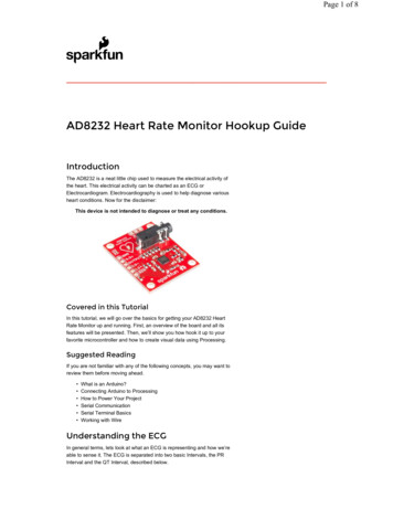
ElementDescriptionPart type name7404Logic decalINV (inverter)PCB decalDIP14 (14 pin dual in-line package)Electrical parametersSix logical gates (A through F) using 12 of the 14 pinswith one power pin and one ground pin.You can create a part type in PADS Logic or in PADS Layout; however, you canonly create a Logic decal in PADS Logic, and a PCB decal in PADS Layout.PCB decal editorThe PCB decal is the physical representation of the part, often called itsfootprint. The PCB decal contains a number of terminals representingcomponent pins and a component outline. You create PCB decals in the PCBDecal Editor.On the Tools menu, click PCB Decal Editor.Once you enter the PCB Decal Editor, text labels and a PCB decal origin markerappear: The NAME text label is a placeholder for the reference designator of the part. The TYPE text label is a placeholder for the part type name of the part.Wherever you position these labels in the decal is where the referencedesignator or part type appears when a component using the PCB decal isadded to the design. The origin marker identifies the origin of the part, which is used whenmoving, rotating, or otherwise positioning the part in PADS Layout. Thedecal origin is also referenced by automatic assembly and pick-and-placemachines.Creating a PCB DecalIn the following exercise you will create a PCB decal for the 26-pin connector,shown below, by adding new terminals, a component outline, and assigningpad stacks.Creating Library Parts8
Add a terminalThe first step in defining a PCB decal is to add a terminal for each pin of thepart. Each terminal is sequentially numbered as it's added to the decal. Eachterminal number is its pin number, for example, terminal 1 is pin number 1,terminal 2 is pin number 2, and so on.1. Drafting button Terminal button.When the Add Terminals dialog box opens, accept the defaults and click OK.You are now in add terminal mode. Each click of the mouse button will add anew terminal at the location of the click.2. Set the design grid to 50 by typing g50 and pressing Enter.3. Set the display grid to 50 by typing gd50 and pressing Enter.4. Move the pointer over the decal origin marker and click to add the firstterminal at the decal origin.5. Move the pointer to location X50,Y50 (using the X,Y location display on theStatus Bar as a guide) and click to add the second terminal.Add multiple terminals using Step and RepeatYou can use the Step and Repeat command to quickly replicate objects, such asterminals, in a repetitive pattern.1. Select button.2. Right-click and click Select Terminals.3. Click the first terminal.4. Ctrl click to add the second terminal to the selection.5. Right-click and click Step and Repeat.6. In the Step and Repeat dialog box, click the Linear tab.Tip: The Radial Placement licensing option enables Polar and Radialplacement tabs.7. Click Right as the Direction, set the Count to 12, the Distance to 100, andthen click OK.Result: Twenty-four new terminals are automatically added to complete theconnector pin pattern.Assign pad shape and sizeThe next step in defining a decal is to assign pad shape and size. This isperformed in the pad stack editor.1. Setup menu Pad Stacks.2. Select Mounted Side from the Shape: Size: Layer list.Creating Library Parts9
Tip: Mounted Side is the side of the printed circuit board, front or back, onwhich components are mounted.3. In the Parameters area, click the Circular pad shape button.4. Also in the Parameters area, change the diameter of the pad by typing 55 inthe Diameter box.5. In the Drill Size box, type 28.6. To change the pad shape and size for the remaining layers, select InnerLayers and Opposite Side from the Shape: Size: Layer list, and set thepad diameter for each to 55.Tip: Inner Layers are design layers other than those on the top or bottom of aprinted circuit board. Inner layers may be routing layers, plane layers, or acombination of both. Opposite Side is the outer layer of the printed circuitboard opposite the Mounted side layer.7. Click OK.Tip: If the drill holes are not visible, type do and press Enter. The do modelesscommand toggles the drill outline display setting.Create a component outlineCreate part outlines with the 2D line drawing tool.1. 2D Line button.2. Right-click and click Rectangle.3. Position the pointer at the upper left corner of the outline by typings -100 100 (s, negative 100, space, 100) and pressing Enter.4. Without moving the pointer, press the Spacebar to initiate a new rectangularpolygon.5. Move the pointer to location X1350,Y -50.6. Click to complete the polygon.Adding keepouts to a PCB decalIn PADS Layout, you have the capability to define a region as a keepout for vias,traces, and other design objects. You can define keepouts on the PCB or withinthe PCB decal.In this exercise you will define a via keepout for the connector.1. Keepout button.2. Right-click and click Rectangle.3. Position the pointer at the upper left corner of the outline and click to begindrawing the keepout rectangle.Creating Library Parts10
4. Move the pointer over the lower right corner of the outline and click tocomplete the polygon.5. In the Add Drafting dialog box, in the Restrictions area select the Via andJumper check box to assign the restrictions for the keepout.6. In the layer list click All Layers to assign the keepout to all layers.7. Click OK to complete the definition of the keepout.Assigning PCB decal attributesIn PADS Layout you assign attributes; such as a manufacturer's part number,corporate part number, height, and other component specific information tocomponents or part types. You can also assign attributes to PCB decals.Add a height attribute1. Edit menu Attribute Manager.2. If the Geometry.Height attribute is not already in the list:a) In the Decal Attributes dialog box, click Browse Lib. Attr.b) In the Browse Library Attributes dialog box, click Refresh to updatethe attribute listing to view all attributes used in the library.c) In the Attribute list click Geometry.Height, and click OK to add theheight attribute to the decal.3. Double-click in the Value box, and type 300 (in current-unit mils for .300”).4. Click Close.Adding attribute labels to a PCB decalYou display attributes in the design as text labels. You can also add additionallabels to accommodate different size and location requirements for referencedesignators. The visibility and position of each label is managed within theLayout Editor.You can predefine locations for attribute labels by adding placeholder labels inthe PCB decal. The placeholders act as the defaults for new labels added or madevisible in the Layout Editor.Add a reference designator label to the decalIn this exercise, you will add an assembly drawing reference designator label tothe connector decal. Labels are added to the PCB decal using the Add NewLabel command.1. Add New Label buttonCreating Library Parts.11
Result: After you click the Add New Label button, a new label appears justbelow the current Name label and the Add New Decal Label dialog boxappears.2. In the Attribute list, click Ref. Des. to assign the new label as the placeholderfor an additional reference designator label.3. In the Show list, click Value, enabling the display of only the value ofthe attribute.4. Change the position of the label by typing 600 in the X box and 150 inthe Y box. In the horizontal and vertical Justification lists click Centerand Center.5. In the Layer list, click Assembly Drawing Top to assign the text to the topassembly layer.6. Click OK to close the dialog box and complete the addition of the label.Tip: The new label will not appear if a color is not assigned for objects on theAssembly Drawing Top layer in the Display Colors Setup dialog box.Exception: Reference designator colors are controlled by the Pin Num. labeloption instead of Attributes. Part type colors are controlled by the Type labeloption instead of Attributes.Position the other labelsPosition the Name and Type labels in the decal where the text will not beobscured when visible.1. Select button.2. With nothing selected, right-click and click Select Text/Drafting.3. Select each label and to move it press Ctrl E.4. Place them in the approximate location shown in the "Creating a PCB Decal"section at the beginning of the tutorial.5. Click to complete the moves.Save the PCB decalYou created your first PCB decal in PADS Layout. Save it to the library.1. Save button.2. In the Save PCB Decal to Library dialog box, click the \preview library.3. In the Name of PCB Decal box, type 26pinconn.4. Click OK and confirm messages that may appear asking if you want tooverwrite the file.Creating Library Parts12
Creating a new part typeNow that you've completed the PCB decals required for the tutorial, you willcreate a part type for the new 26-pin connector using the part type editor.Assign general parametersThe first steps in creating connector part types are establishing the part type asa connector and assigning a PCB decal.1. File menu Library.2. To create a new part type in the preview library, click \preview in theLibrary list.3. Click the Parts button.4. Click New.5. In the Part Information for Part dialog box, click the General tab.6. In the Logic Family list, scroll and select the CON family type, whichestablishes the default reference designator prefix J for this part type.7. To establish the part type as a connector, in the Options area, select theSpecial Purpose check box, and click Connector.Assign a PCB decalThe next step is to assign a PCB decal for the part type.1. PCB Decals tab.2. In the Library list, click the \preview library.3. In the Filter box, type 26p* and click Apply.4. In the Unassigned Decals list, click the 26PINCONN decal.5. Click Assign to move the decal into the Assigned Decals list.Add part type attributesYou can add attribute labels in the PCB decal. For part types, you add attributesand their respective values. Enter attributes directly into the attribute cell orclick one from a list of all attributes in the PADS library.For this exercise, you will add attributes to the connector part type from thoseattributes found in the library.1. Attributes tab.2. Click Add.3. Click Browse Lib. Attr.Creating Library Parts13
4. In the Browse Library Attributes dialog box, click the Description attributeand click OK.5. Double-click in the Value cell.6. Type CONNECTOR, RIBBON, 26 PIN in the Value cell.7. Click Add again, and repeat the previous steps to add these attributesand values:AttributesValuesCost(leave blank)Part NumberMGEG26RManufacturer #1ACMEManufacturer #2(leave blank)Assign CAE decalsNow assign Logic decals for the part type.1. Connector tab.2. Click Add.3. Click the Browse button from the Special Symbol cell.4. In the Browse for Special Symbols dialog box, select the EXTIN symbol in the \misc library, and click OK.5. Double-click in the Pin Type cell.6. In the list click Source to assign input pins as sources.7. Click Add again, and click the Browse button from the newly added SpecialSymbol cell.8. In the Browse for Special Symbols dialog box, select the EXTOUT symbol inthe \misc library, and click OK.9. Double-click in the Pin Type cell.10. In the list, click Load.Save the part typeNow that the part type definition is complete, save the new part type.1. Click OK.2. In the Save Part Type to Library dialog box, navigate to the \previewlibrary, name the part type 26pinconn, and click OK. Confirm any messagesthat appear asking if you want to overwrite the file.3. In the Library Manager dialog box, click Close.Creating Library Parts14
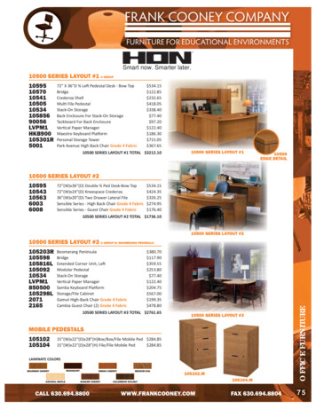
Creating PCB decals using the Decal wizardThe PCB Decal Editor provides dialog box-driven PCB decal wizards. Thesewizards provide automated tools for creating standard footprint patternsautomatically.Create a SOIC decalNow that you've experienced PCB decal creationusing the interactive tools in the PCB Decal Editor,you will create the SO28 PCB decal, shown at right,using the automated tools in the PCB Decal Editor.1. On the Drafting Toolbar, Wizard button.2. In the Decal Wizard dialog box, click the Dual tab.3. In the Decal area, in the Device type section, click SMD.4. In the Orientation section, click Horizontal.5. In the Pins area, enter the following:a. Pin count box, type 28b. Width box, type 24c. Length box, type, 90d. Pin pitch box, type 507. In the Row Pitch area, click Center to Center and in the Value box, type 450.8. In both the Pin 1 shape and Pin shape sections, click Oval.9. In the Placement outline area, in the width box type 600, and in the Heightbox type 800.10. In the Thermal pad area, clear the Create check box.11. Click OK. The PCB decal is automatically created.Result: You just created a 28-pin SOIC in a few easy steps.To return to the Layout Editor: On the File menu, click Exit Decal Editor.Do not save a copy of the design.You completed the part creation tutorial.Creating Library Parts15
Preparing a DesignPreparing a design involves the establishment of the layer arrangement, settingdisplay colors, defining a board outline and a few other activities.In this lesson: Establishing a layer arrangement for the PCB Setting display colors Saving a Start-up file Creating a board outline Modifying the board outline Adding non-electrical objectsRestriction This tutorial requires the Drafting Editing, ECO, and General Editinglicensing options.To determine whether you can proceed: On the Help menu, click Installed Options.PreparationIf it is not already running, start PADS Layout. Make sure you are starting witha blank screen, or new design.Establishing a layer arrangement for the PCBPADS Layout enables you to define layer arrangements for the PCB includingthe number of layers, the nets associated with embedded plane layers, layerstackup, and layer thickness.The tutorial design is a four-layer PCB with two internal plane layers supportingmultiple plane nets. In this section you will define the layer arrangement for thetutorial design using the layer definition tools of PADS Layout.Increase the number of layersThe default design is a two-layer PCB.1. Setup menu Layer Definition2. In the Layers Setup dialog box, in the Electrical Layers area click Modify.Preparing a Design16
3. In the Modif
between the modeless command and the value. It’s required in PADS Router. Tips: Use the g modeless command for global grid settings. Entering g500 sets the design grid and via grid to 500 mils. To set the via grid separately, type gv and press Enter. Instead of specifying