Transcription
TRANSISTORRADIOSERVICINGMADEEASYBY WAYNE LEMONSvolume explaining only whatyou need to know to repairtransistor radiosat a profit.
1.95Cat. No. TRE-1Transistor RadioServicingMade Easyby Wayne LemonsHOWARD W. SAMS & CO., INC.THE BOBBS-MERRILL COMPANY, INC.Indianapolis New York
FIRST EDITIONFIRST PRINTING - MARCH, 1962TRANSISTOR RADIO SERVICINGMADE EASYCopyright 1962 by Howard W. Sams & Co., Inc., Indianapolis 6, Indiana. Printed in the United States of America.Reproduction or use, without express permission, of editorialor pictorial content, in any manner, is prohibited. No patentliability is assumed with respect to the use of the informationcontained herein.Library of Congress Catalog Card Number: 62-13499
PrefaceThis book was written to help you, the service technician,understand and repair the many transistor radios on themarket today-at a profit. I cannot guarantee you'll be anexpert after reading this book, but you will be in a muchbetter position to become an expect.When I first started to service transistor radios, I gavemyself six months to become proficient enough to earn aprofit. When the six months were up, I found I had beenmore optimistic than accurate. Even after nearly two years,I still come across new and puzzling problems. I can say,though, that I am making a good profit from transistor radioservicing. Naturally, I made mistakes, but I profited bythem. Through this book, I hope you, too, will profit fromwhat I have learned.Only incidental theory is presented, as an adjunct to thethorough coverage of practical troubleshooting and repairtechniques. Therefore, you will gain more from this bookif you have a good background in radio theory.The first part of this volume deals with practical transistorfacts, derived from years of servicing experience. Since youneed not be concerned with "holes," barrier levels, etc., inservicing, the explanations are confined to such factors aspolarity, gain, biasing, impedance, and general operation.Also, as you will learn at the outset, there is quite a differencebetween pure theory and actual practice.While studying this book, you will actually begin to solvemany problems ( in your mind's eye) before you realize it.Once you have absorbed the contents, you will find youhave all the knowledge necessary to service and repair anytransistor radio on the market, and will be able to realizemore profits from transistor radio servicing.
My thanks to Mr. H. S. King, Philco Corp., for informationon "no-output-transformer" circuits; and Messrs. Briesacher,Martin, and DeAngio of General Supply Co., Waynesville,Mo., whose suggestions, hospitality, and facilities helpedmake this book possible.w A YNEJanuary, 1962LEMONS
ContentsChapter IWhat You Should Know About Transistors7Remembering Polarities-What the Ohmmeter and Circuit "see"-Gain versus Bias-How Rugged are Transistors?-TransistorBasing-Transistor SchematicsChapter 2Mixer-Oscillator Circuits19Separate Oscillator-Troubleshooting-Causes of a Dead Oscillator - Antenna Circuit Troubles - Substituting Transistors Checking an Antenna with a Grid-Dip MeterChapter 3IF Circuits and Their Repair .30Neutralization-Troubleshooting-Checking IF TransformersOther IF Circuits-Summary of IF TroublesChapter 4Detector and AGC Circuits40Transistor Detectors-Automatic Gain Control-TroubleshootingChapter 5Servicing the Audio Stages49Reflex Amplifiers-Output Amplifiers-Troubleshooting-Replacing TransistorsChapter 6Over-All Service Techniques .So Let's Repair a Radio-Intermittents62
Chapter 771Rapid Diagnosis and RepairIn-Circuit Checking-The "Razor-Blade" Technique-How toRemove Parts from Printed Boards - Replacing Parts - HeatSinks-Repairing Broken BoardsChapter 8Alignment and Tracking83Dial Calibration-Pitfalls of Tracking-Alignment IndicatorsSealed Alignment Screws-How often are Alignment and Tracking needed?Chapter 9Repairing the "Weak" and "Not Quite Right" Radios90Signal Tracing-Audio Stage Gain-Is It the Design?-Hints onImproving PerformanceChapter 1097Noise, Oscillations, Squeals, and MotorboatingNoise-Inherent Noise-Squeals, Oscillations, and Motorboating-Battery Electrolyte-Open Printed CircuitsChapter 11. 104Tools and EquipmentEquipment Needed-Schematics and Service Information-PartsSuppliesChapter 12Where to get Replacement Parts. 114List of Parts SuppliersIndex . 123
CHAPTER IWhat You Should KnowAbout TransistorsTo become proficient in transistor circuit analysis there isnothing more important than starting to think in transistorterms. You have to know what a transistor consists of, thevoltage polarities of its elements, and how your equipment"sees" the transistor.Valence bonds, impurities, donor and acceptor atoms, andthe like may make for noble conversation-but they won'thelp much in troubleshooting a circuit. You've been told thatthe current carriers inside the transistor are electrons in NPNtypes, and holes in PNP types. Don't let this apparent ambiguity disturb you, though. Imagine that they're electrons,lead pellets, or billiard balls-for service work, it reallydoesn't matter. You've never seen the current carriers ( electrons) in a vacuum tube, but chances are it hasn't disturbedyou.From a service standpoint, NPN and PNP types bothwork exactly alike, except that they require opposite workingvoltage polarities. If you reverse the leads of your voltmeterwhen going from a PNP to an NPN on a voltage check,you'd never know which type you were servicing. However,you do need to remember the names of the transistor elements. This isn't hard, especially if you are familiar with vacuum tubes. The emitter emits current carriers, just like thecathode of a vacuum tube; and the collector collects thesecarriers, just like the plate of a tube. Likewise, the base ( between the collector and emitter) controls the collector current ( and as a consequence, the emitter current), again muchlike the grid in a vacuum tube. But a transistor isn't a tube!So don't hold yourself too closely to tube analogy-it doesn'talways work.7
How does a transistor amplify? It is mainly a function ofcircuit impedance, or resistance transfer ( hence the name,transistor). As an example, the input of a common-emittercircuit is of fairly low impedance, while the output is fairlyhigh. Therefore, the transistor amplifies because it has theability to transfer the current from the low-resistance ( impedance) input into the high resistance of the output withvery little loss. It follows, then, that if the same amount ofcurrent flows in the high-impedance circuit as does in thelow-impedance circuit, there will be a greater voltage dropacross the high impedance. For example, if 1 milliamp flowsin an input circuit with an impedance of 500 ohms, therewould be a 0.5-volt drop. If that same 1 milliamp were transferred ( assuming no losses in the transistor) to a 10,000-ohmoutput impedance, the voltage drop would be 10 volts-or,in other words, a gain of 20 volts in the circuit. This is as faras we will go into transistor theory. However, what is important, for service work, is that transistors do have gain. Inthem, a current change produces a power change; whereasin a tube, a voltage change produces a power change.Incidentally, low-impedance devices are known as currentdevices.REMEMBERING POLARITIESSince there are two basic types of transistors, the PNP andthe NPN, how does one remember what the polarity of applied voltage is in each type? The key is the middle letter,which actually designates the transistor type. If the P is inthe middle ( as in NPN ) , you know two things: first, thecollector voltage is positive with respect to the emitter; andsecond, when correctly biased, the base voltage is also ( afraction of a volt) more positive than the emitter. On theother hand, if the middle letter is an N ( as in PNP), thenthe collector and base voltages are negative. Remember thatthe base of a transistor is always biased in the same polarityas the collector. This is opposite to tube polarity, where thegrid is usually negative with respect to the plate, which ispositive.Small-signal transistors ( those used in RF and IF stages)usually have about a 0.1- to 0.3-volt bias, in order to produce8
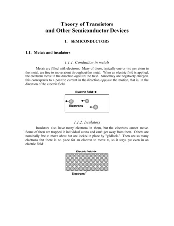
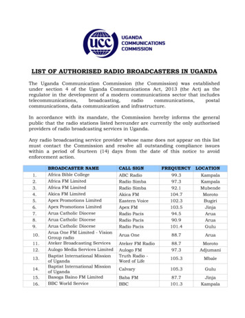
about 1 ma of collector current. However, the collector voltage may be anywhere from 1 to 22½ volts. Bias should bemeasured from emitter to base, and the collector voltagefrom emitter to collector.WHAT THE OHMMETER ANDCIRCUIT "SEE"What does a transistor look like to an ohmmeter? It lookslike two diodes back to back, as shown in Fig. 1-1. Since thediodes have a high reverse resistance, this is represented byCOLLECTORCOLLECTOR\\OHMMETEREMITTERPNP(A) PNP type.OHMMETEREMITTERNPN(B) NPN type.Fig. 1-1. Transistor equivalent circuits.the two unknown resistors across the diodes. Just as diodescan be checked with an ohmmeter, so can transistors. Thereare some limitations to ohmmeter transistor testing, but theyare not serious. Ohmmeters are probably as accurate as inexpensive DC leakage-gain checkers. True, you can't measure gain with an ohmmeter, but then a transistor that hashigh DC gain may not work at all, or may not work as wellas another with a lower DC gain. The reason is that a DCgain check tells you nothing about the transistor frequencycharacteristics, the circuit input and output impedances, orthe dynamic input and output impedances of the transistoritself. Actually, an ohmmeter may even spot a transistor witha loss of gain, since the gain of a transistor seldom changes.So the last thing to suspect, in cases of low gain, is the transistor itself-but don't think the transistor is above suspicion,9
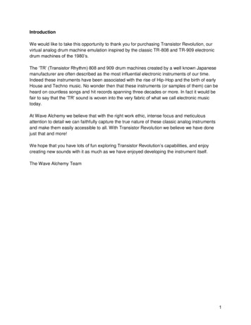
for despite whatever you may have heard or read, transistorsdo fail, and with rather surprising regularity!Fig. 1-2 shows how to make the ohmmeter test. Place thered lead on the base, touch the collector with the black lead,and note the reading. Now touch the black lead to the emitter and again note the reading. If the base-to-collector reading is low, then the base-to-emitter reading should also beBLACKQREDFig. 1-2. Transistor testing with an ohmmeter.low. Likewise, if the former is high, then the latter shouldalso be high. Now move the black lead to the base. Touchthe red lead to the collector and note the reading, and thentouch it to the emitter and again note the reading. These tworeadings should be the opposite of the first two. For instance,if the first two readings showed a low resistance, the last twoshould read high, and vice versa.10
Now measure the resistance between the collector andemitter. Surprisingly, here is where most transistor shortsoccur; usually the diode action between base and collectorand between base and emitter is unaffected. Fig. 1-3 showshow the emitter-collector short evidently occurs. Excessivecurrent punctures a hole in the base by melting its material.At the same time, the melted material physically connectsthe emitter and collector together. While there is no shortCSHORTBBASEE( A) Physical short.(B) Equivalent circuit.Fig. 1-3. Collector-to-emitter short.between the base and either the emitter or collector, thereis actually a short between the emitter and collector. Thiscan happen because the base is so thin that it literally is disintegrated around the area of the leakage path between theemitter and collector, as shown in Fig. 1-3.GAIN VERSUS BIASUnlike in RF and IF vacuum tubes, the gain of a transistor does not change drastically as the bias voltage changes.However, within certain limits, the collector current doeschange, and yet the gain of the circuit may remain fairlyconstant. ( If you doubt this, try testing a transistor on adynamic AC checker that has a bias-change provision.) Thisis why the special AGC circuits discussed in Chapter 4 arenecessary. Only at the critical values of bias near cutoffand saturation is the gain affected to any great extent by11
bias changes. If, then, you find a transistor with a bias ( emitter to base) of 0.1 volt, don't be disturbed even though theservice information may show 0.15 or 0.2 volt. As long as thebase has the same polarity as the collector and between a0.1- and 0.3-volt difference with respect to the emitter, it ismost likely correct. As an example, the converter stage doesnot always appear to have the correct bias. The bias may bezero, only very slightly forward, or even reversed. This isnormal, since the oscillator sine-wave voltage drives the converter into conduction on each positive ( negative, depending on the transistor type) excursion.HOW RUGGED ARE TRANSISTORS?A common misconception, fostered from the early daysof transistors, is that transistors must be handled with kidgloves. All sorts of precautions have been given wide publicity. Don't worry too much about transistors, though.Chances are you won't ever burn one out if, say, you don'tuse a heat sink. The fact is, in some sets you can't even getto the transistor leads to apply a heat sink. You can-andshould-use a soldering iron of about 75 watts, especiallywhen removing parts, including transistors, from the board.You'll read more about this in Chapter 7.A transistor can be checked with just about any serviceohmmeter and never be damaged. The battery voltage of theohmmeter is unimportant if the meter movement is sufficiently sensitive. In fact, you can apply 500 volts across atransistor-as long as you use a suitable resistance in serieswith it to reduce the current to a milliamp or so. Transistorsare used every day in just such circuits, and the series resistance in any standard ohmmeter will limit the current toa safe value while they are being checked.You can accidentally reverse the battery polarity on atransistor radio and probably not damage a single transistor.You may damage an electrolytic, but only if the radio wereleft on for quite a while.You can heat the case of some transistors to the pointwhere you can't touch them without burning yourself, andthey will likely go right on working-or, if they quit operating, they will again work normally after permitted to cool.12
You can increase the reverse voltage on a transistor untilit "zeners" ( breaks down in the reverse direction) and, unless the current is excessive, the transistor will probably beall right when the voltage is removed.With anything so rugged, you might wonder if they everfail. Of course they do! They open-that is, the element separates from its external lead. They short between any two elements, but usually between emitter and collector. They develop leakage, one of the hardest troubles to diagnose eitherin or out of the circuit. Two identical transistors will not display the same amount of leakage. Even in a single transistor,leakage can vary, and usually does with heat and appliedvoltage. For this reason, a transistor may check "good" in aleakage tester or with an ohmmeter, yet not work in the circuit. Transistors in a circuit may have as much as 9 volts( or more) on the collector, while most testers use only 4½volts for testing. A transistor can perform perfectly with 4½volts and refuse to work with 5 volts. You'll learn more, inlater chapters, about how to spot this trouble.TRANSISTOR BASINGAbove all, memorize the base-lead layouts of transistors.This isn't hard to do, and it will provide you with the key forall transistor circuit tracing. Tube printed circuits have sockets as landmarks, but in transistor radios you'll seldom finda transistor socket. You must know the position of the leads!Just about every radio you'll encounter will have one of thefour basic base layouts shown in Fig. 1-4. Remember thesetwo rules:1. The base lead is always between the emitter and col-lector.2. The collector lead is marked by either a color dot orline, or is set off by itself ( Fig. l-4A).Probably the most common base layout today is the "tophat" design shown in Fig. l-4B. You can remember this arrangement more easily from the familiar schematic symbol.Hold the transistor leads so they point toward you, with thebase (middle) lead to the left. The connections will then13
be the same as the schematic symbol shown in Fig. l-4C.This symbol is used in nearly all recent schematics.The Philco basing arrangement, shown in Fig. l-4D, isopposite that of the "top hat" design, but the collector ismarked. With the leads pointing toward you ( the collectorat the top), the base connection is at the right, instead ofthe left as in the "top hat" design.cec: :: SHIELD LEADWHEN USED( A) Collector set EMITT off by itself.(B) "Top-hat" design.COLLECTOR"6 ---17\::B EL- ----J:COLLECTOR"6:EI I( C) Triangular leadarrangement.( D) Philco design.Fig. 1-4. Transistor lead basing arrangements.TRANSISTOR SCHEMATICSInterpreting transistor schematics can cause you somegrief, especially at first. You can get over this hurdle if youkeep a few basic facts in mind. First, get the schematicsymbols down pat. Figs. l-5A and l-5B show the standardtransistor symbols for a PNP and an NPN, respectively. Thedifference, as you can see, is in the arrow, which denotes thepolarity of the emitter. The direction of the arrow tells youwhether the transistor is a PNP or an NPN. A good rule toremember is; the arrow always points to the N section of thetransistor.In Fig. l-5A the arrow points toward the base, which isthe middle section of the transistor; the middle letter of thetype designation then is N. Thus, whenever the arrow pointstoward the base, the transistor is a PNP.If the arrow points away from the base, as in Fig. l-5B,then it denotes a negative emitter and the transistor is there14
fore an NPN. The rule again: the arrow always points to theN section. To make the rule easier to remember, imagine thearrowhead as an imaginary N.It might be well to point out, though, that on occasionyou may actually find an incorrect arrow symbol, especiallyin earlier schematics. For example, the arrow may be pointPNPB ENPNB E(A) PNP(B) NPNFig. 1-5. Standard Schematic symbols.ing toward the base on an NPN transistor. You can easilyspot this mistake if the voltages are given, or by tracing thevoltage polarities. Remember that the middle letter of thetype designation denotes the polarity of the collector andbase with respect to the emitter. Note in Fig. 1-6 that thebase voltage is 0.4 volt positive-or 0.1 volt more positivethan the emitter-and that the collector is 6 volts positive(5.7 volts more positive than the emitter). Obviously this isan NPN transistor. Equally obvious is that the schematicsymbol is incorrect, since it depicts a PNP ( arrow pointedtoward the N material). With this type of error, it's a goodidea to correct the drawing for future reference.In nearly all circuits today, the transistor is drawn with thebase at the left. Occasionally, ( for convenience) one of theoutput transistors may be drawn upside down in class-Boutput circuits, but electrically it remains unchanged.Fig. 1-6. Incorrect schematic symbol.PolarityNow let's take up the next important clue to solving thetransistor schematic. Since the design engineer has a choiceof using transistors of either polarity, he is privileged to makethe ground positive or negative. Unfortunately for the schematic reader, the designer is not held to a positive ground15
for PNP's or a negative ground for NPN's-the ground maybe positive or negative with either type. Moreover, some ofthe transistors in a single radio may be NPN's and othersPNP's.Fig. 1-7 shows two typical PNP transistor circuits. In Fig.l-7A, the positive side of the battery is grounded; the negative side supplies the proper polarity to the collector andbase. Fig. l-7B shows a circuit with the same transistor andparts, and yet the negative side of the battery supply isgrounded. There is certainly nothing wrong with this circuit,since the negative side is still tied to the collector. The emitter, which was grounded in Fig. 1-7A, is tied to the positive0IOK2"'g"'"'n - 30MFDn ( A) Positive ground.(B) Negative ground.Fig. 1-7. PNP circuits with reversed polarities.side of the battery in Fig. l-7B. Bias is still supplied in exactly the same proportion from ground.Fig. 1-8 shows the same circuits as Fig. 1-7 except thatNPN transistors are used instead of PNP's. Notice that thebattery polarities are reversed from those in Fig. 1-7. Otherwise the circuit performance is identical to that of Fig. 1-7.Fig. 1-9 shows how a designer might use both a PNP andNPN transistor in consecutive circuits. It's all a matter ofpolarities between the emitter, base, and collector. In thisexample, the NPN emitter bypass is returned to groundbut it could have been tied to the negative line if more convenient. It seems that most designers return their bypassesto ground, but this does not change the operation of thecircuit in any way. It does, though, make for some peculi16
arities in the polarity of electrolytics. Look again at the basecircuit electrolytic bypass. The negative side of the bypassis connected to the base, but an NPN ( remember the rule)has a positive base-but only with respect to the emitter,however, not necessarily positive with respect to ground. (A) Negative ground. (B) Positive ground.Fig. 1-8. NPN circuits with reversed polarities.In this circuit, if you measured the base with respect toground, you would find it negative by about 5.5 volts. Nowif you measured from base to emitter, you would find thebase more positive than the emitter by 0.1 volt, just as itshould be. The collector is zero volts with respect to ground,but measured from the emitter it is 5.6 volts positive.Voltage ReadingsVoltage given on schematics are nearly always taken withrespect to ground (common). This makes it pretty hard tomeasure the bias voltage on the NPN transistor in Fig. 1-9,since there is such a little difference between 5.6 volts and5.5 volts. The recommended procedure, at least at the beginning, is to measure bias voltages on a low-range scale of yourmeter, between base and emitter, making sure the polarityis correct.Measuring Transistor CurrentSometimes you may want to know how much current aparticular transistor is drawing. The easiest way is to meas17
6Vn Fig. 1-9. Circuit using both a PNP and NPN from acommon power source.ure the voltage drop across the emitter resistor and calculatethe current from Ohm's law. If there is no emitter resistor,measure the voltage across the collector resistor instead.Most RF, IF, and mixer-oscillator transistors will be biasedto draw about 0.7 to 1.5 milliamperes.18
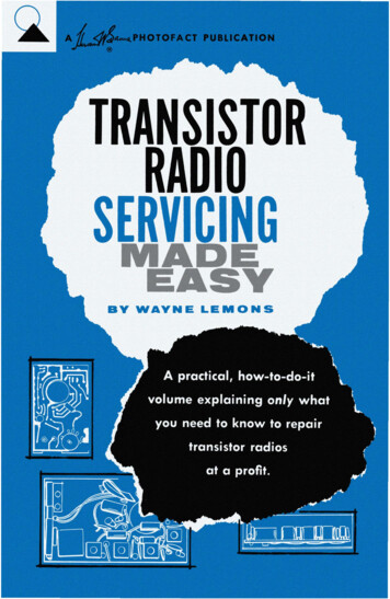
CHAPTER 2Mixer-Oscillator CircuitsThe mixer-oscillator is usually the first stage in transistorradios, although several late-model radios have an RF stageahead of it. The mixer-oscillator performs three functions:It generates a local-oscillator signal, mixes that signal withthe incoming RF, and then amplifies the resultant beat between these two frequencies. This beat is the IF frequency.As with tube mixers, a transistor must be biased as a detector, or nonlinear amplifier. In tube circuits this bias isgenerally provided by the negative voltage drop across theoscillator grid resistor, as shown in Fig. 2-1. In transistorcircuits, however, no such high impedance exists, so the biasis supplied by inserting a lK to 5K resistor in the emitterlead of the transistor.In tube circuits it is common practice to check for oscillations by simply reading the oscillator grid voltage. If thevoltage is negative by more than two or three volts, it is apretty sure sign that the oscillator is working. No such simple test can be made on transistor oscillators, however. True,some voltage is developed when the transistor oscillates, butthe amount is so small that it is impossible to tell whether itis caused by normal bias conditions or by oscillations. Thereare, though, a couple of ways you can tell whether the oscillator is working. Place your meter on a low-voltage scaleand measure the bias voltage between the emitter and base.The exact amount of this voltage is not too important. ( Depending on the circuit design, the voltage may be such thatthe transistor is slightly forward-biased, near zero, or even19
reversed-biased.) Now, while monitoring the bias, turn theradio tuning dial from one end of the band to the other.If the oscillator is working, the bias voltage will change asyou move the dial. Another way to check bias is to short outthe oscillator section of the tuning capacitor as you monitorthe voltage. The bias voltage should change noticeably whenyou do this. A caution here, though-in some circuit designs,the tuning-capacitor stator is tied directly through the oscillator coil to the supply voltage. In this case, shorting thecapacitor may result in damage to the coil and you won'tknow whether the circuit is oscillating or not.NEG VOLTAGEFig. 2-1. Method of developing biasof oscillator grid.B The actual circuit used in transistor radios where one transistor does both the oscillating and mixing is known as amodified autodyne. An autodyne utilizes the elements of thetransistor so that they do double duty as both a mixer andlocal oscillator.Fig. 2-2 shows the circuit function. Here, energy from oscillator tank coil L3 is fed through C2 back to the emitter,and energy from the collector circuit is coupled through L4to sustain oscillations. Both C3 and C4 are collector-currentbypasses for the oscillator, and Cl is the base bypass. Emitterresistor R3 has a twofold purpose: it presents an impedanceto prevent the feedback voltage from being grounded, and itdevelops voltage to keep the transistor biased near cutoff.Ll-L2 is the loopstick antenna. L2 has only a few turnswhich match the high impedance of Ll to the low impedance of the transistor base circuit.Some oscillator circuits use base instead of emitter feedback as shown in Fig. 2-3. Notice the similarity to the circuit20
MIXER /OSCILLATORPNP@QJ @@q) CTOIFTRANSISTOR@@ Fig. 2-2. Collector-to-emitter feedback.in Fig. 2-2, except that now the feedback voltage goes to thebase through Cl instead of to the emitter through C2. Theprimary terminals of oscillator coil L4 are reversed to provide the correct feedback phase; otherwise the circuits areMIXER/OSCILLATORqJ PNP@@@C@ Fig. 2-3. Collector-to-base feedback.21
identical. Both circuits use the same bias and emitter resistors, the same size of bypass capacitors for Cl and C2, andthe same transistor.All other mixer-oscillator circuits are variations of thesetwo. Fig. 2-4 shows a circuit using a three winding transformer, but in reality it is no different from the one in Fig.2-2. L5 is used for the emitter pickup rather than for tappingthe tank coil as in the first two circuits.Fig. 2-5 might at first appear to be different but it alsoclosely resembles the basic circuit of Fig. 2-3. In Fig. 2-5 thefeedback is from the collector to the base through L4 and Cl.The tap on L3 now becomes the collector feedback winding.The IF transformer is connected directly to the collector andFig. 2-4. Isolated-coil feedback.is in series with part of the oscillator coil. In most circuitsthe oscillator coil is connected to the collector and the IF tothe power source. Except for some special diode AGC circuits, it makes no difference whether the oscillator coil orthe IF is connected to the collector.Note in this circuit that base bias resistor Rl is not used;the designer depends on the reverse leakage of the transistorto act as Rl. This could make the circuit a little more criticalif you have to change transistors. In such case you mighthave to juggle the value of R2 somewhat to arrive at optimum performance.22
MIXER /OSCILLATORPNP ----@- Fig. 2-5. Collector-to-base feedback.SEPARATE OSCILLATORFig. 2-6 shows a configuration using a separate oscillatortransistor. Essentially this is the same kind of configurationused in the autodyne circuit. Feedback is to the base, andthe oscillator voltage is injected ( through a .05-mfd. capacitor) into the mixer from a tap on the oscillator coil.TROUBLESHOOTINGYou have already learned a couple of ways of tellingwhether the oscillator is working or not. Another way is tobring an operating radio close to the dead radio. Place onedial near the center of the broadcast band. Now sweep theother dial through its range until you hear ( or don't hear)a beat (whistle). If you do hear a beat, then it is obviousthat both oscillators are functioning.A tuned signal tracer is an ideal instrument for checkingthe oscillator. It will tell not only whether the stage is working or not, but also at what frequency. A high-impedanceearphone plugged into a low-frequency grid-dip oscillator23
( GDO) will let you hear the beat between the GDO and theradio oscillator when both are tuned to the same frequency(Fig. 2-7). Remember, the radio oscillator should be at theIF frequency-usually 455 kc above the dial reading. For example, if the radio dial is set to 1000 kc, you should hear thebeat near 1455 kc on the GDO. If the radio is operating fromthe front-end on ( that is, you are able to hear noise throughMIXERNPN---E4.7KI00K.001I0K470Fig. 2-6. Separate oscillator and mixer circuits.the radio, but no stations), chances are the oscillator is notoperating. You can usually confirm this suspicion by simplybringing the suspected radio near a fluorescent lamp or othernoise source. Now tum the oscillator slug; if the noise becomes maximum as you do, the oscillator is working. If thereis no change, then the oscillator isn't working ( or the antenna circuit may be defective).Together with conventional troubleshooting methods, alow-range AC voltmeter or a wide-band oscilloscope will also24
indicate whether the oscillator is working, although of courseneither will tell you whether at the correct frequency.CAUSES OF A DEAD OSCILLATORProbably the most common cause of oscillator failure isan open antenna base coil. In any of the circuits except thatof Fig. 2-6. if antenna base coil L2 is open, the oscillator willnot work. In Fig. 2-2, for example, if L2 opens there will beno base bypass through Cl, and
While studying this book, you will actually begin to solve many problems ( in your mind's eye) before you realize it. Once you have absorbed the contents, you will find you have all the knowledge necessary to service and repair any transistor radio on the market, and will be able