Transcription
luxCONTROLmasterCONFIGURATORProduct Manual
masterCONFIGURATOR manual 2.35 11-2021 enTable of Contents1Signs and symbols. 42Introduction. 53Installation. 64 Active window. 95Commissioning5.1Selecting an interface. 12. 125.2 Options. 135.2.1Filter settings. 135.2.2eDALI addressing. 145.2.3Multimaster. 175.2.4 Improvements5.3 Testing the installation. 18. 195.4 Addressing. 195.5 Testing addressing. 255.6 Grouping control gear. 265.7 Setting scenes. 275.8 Saving a project. 286General functions. 296.1Searching for devices. 296.2 Changing a device name. 316.3 Creating a new group. 326.4 Changing a group name. 326.5 Assigning a DALI device to a group. 326.6 Assigning a DALI device to more than one group. 336.7 Removing a DALI device from a group. 336.8 Deleting a DALI device. 346.9 Checking device assignment. 357Configuration. 387.1DALI control gear. 407.1.1Device information. 447.1.2Basic configuration. 447.1.3Status. 497.1.4Tridonic-specific configuration. 507.1.5Device Type 0: Control gear for fluorescent lamps. 1027.1.6Device Type 1: Control gear for emergency lighting. 1177.1.7Device Type 2: Control gear for high-pressure discharge.lamps1337.1.8Device Type 3: Control gear for low-voltage halogen lamps. 137c1
masterCONFIGURATOR manual 2.35 11-2021 enTable of Contents7.1.9Device Type 4: Control gear for phase dimmers. 1407.1.10 Device Type 6: Control gear for LEDs. 1467.1.11 Device Type 7: Control gear for switching function. 1527.1.12 Device Type 8: Control gear for colour converters. 1547.1.13 Device Type 49: Integrated Bus Power Supply (DALI Part.250)1637.1.14 Device Type 50: Luminaire data (DALI Part 251). 1647.1.15 Device Type 51: Energy Reporting (DALI Part 252). 1657.1.16 Device Type 52: Diagnostics & Maintenance (DALI Part .253)1667.1.17 Device Type 255: Multi-device types. 1687.2 DALI XC. 1697.2.1Basic configuration. 1707.2.2Configuration of operating mode "MC". 1737.2.3Status. 1867.3 DALI MC. 1887.4 DALI basicDIM DGC. 1947.4.1Basic configuration. 1957.4.2 Room profiles. 1977.4.3 Device-specific configuration. 1987.4.4 Status. 2007.4.5 Light sensor. 2027.4.6 Motion sensor. 2047.4.7 Remote control. 2087.5 DALI MSensor7.5.17.5.27.5.3MSensor 5DPI 14DALI MSensor 02 (version 2.0)DALI MSensor (version 1.5 and 1.7)7.5.4 DALI MSensor (version 1.3). 208. 209. 224. 240. 2507.6 DALI RM. 2517.7 DALI-RM/S. 2517.8 DALI TOUCHPANEL. 2517.8.1User-defined configuration. 2537.8.2Tunable White. 2577.8.3Factory settings. 2597.9 DALI PS2 Standby. 2607.10 DALI-Somfy animeo Interface. 2627.11 Quick test. 26488.1Tools. 268Command administrator. 2688.1.1DALI commands. 2688.1.2DSI commands. 2698.1.3Command sequence. 270c2
masterCONFIGURATOR manual 2.35 11-2021 enTable of Contents8.2 Control gear wizard. 2738.3 Localisation wizard for DALI XC. 2748.4 Firmware update. 2779Further components10 Appendix. 279. 28010.1 Configuration commands for DALI control gear. 28010.2 Switch and dim commands. 28110.3 Query commands. 28310.4 Reset values. 28310.5 Timing parameter. 284c3
masterCONFIGURATOR manual 2.35 11-2021 en1 Signs and symbolsThe following characters and symbols are used in this manual:1. Individual steps in the instructions are numbered.wÜSingle-step instructions are indicated byw at the beginning of the line.After a step has been described, a description of the expected results will follow. These results are indicated byat the beginning of the line.–Requirements which need to be checked before carrying out a step are indicated by –.iIndividual notes can be recognised by . In addition, notes are identified by the word Note.cÜi4
masterCONFIGURATOR manual 2.35 11-2021 en2 IntroductionThe masterCONFIGURATOR software is a configuration and parameterisation program for DALI devices. This softwarecan be used to set up a DALI control line and configure individual control gear and control units.Basic functions· Addressing· Grouping· Setting scenes· Parameterising DALI devices· Configuring DALI and DSI commands· Creating command sequences· Testing installation, addressing and functionsiNoteThe masterCONFIGURATOR software is designed for online operation. If DALI devices areconfigured offline, faults may occur.c5
masterCONFIGURATOR manual 2.35 11-2021 en3 InstallationThis section covers the system requirements for the masterCONFIGURATOR software and how the software isinstalled.System requirementsIn order to make full use of the functionality of the masterCONFIGURATOR software, the following are required:Operating system· Windows 10· Windows 7· Windows XPiNoteThe chapter Changing compatibility modechange the compatibility mode.Screen resolutionMinimum XGA (1024 x 768 pixels)CommunicationUSB or COM interface8will tell you how you canTable 1: System requirementsInstalling software as administrator1. Run the file masterCONFIGURATOR Vxxx.exe as administrator.a. Right-click on file.Ü Submenu is displayed.b. Click on Run as administrator.2. Click on Next.The setup wizard appears.Ü3. Follow the setup wizard steps.The masterCONFIGURATOR software is installed.Ü4. Follow the setup wizard steps.The DALI BusServer software is installed.ÜiNoteThe masterCONFIGURATOR software can be accessed by going toStart Programs Tridonic masterCONFIGURATOR or via thedesktop.shortcut on theInstalling software without administrative rights1. Run the file masterCONFIGURATOR Vxxx.exe.2. Click on Next.The setup wizard appears.Ü3. Follow the setup wizard steps.The masterCONFIGURATOR software is installed.Ü4. Follow the setup wizard steps.The DALI BusServer software is installed.Üc6
masterCONFIGURATOR manual 2.35 11-2021 en3 InstallationiNoteIf the masterCONFIGURATOR software is installed without administration rights, aninstallation path with write permission must be selected. An installation to the default path isnot possible because of missing write permission for non-administrators.iNoteThe masterCONFIGURATOR software can be accessed by going toStart Programs Tridonic masterCONFIGURATOR or via thedesktop.cshortcut on the7
masterCONFIGURATOR manual 2.35 11-2021 en3 InstallationChanging compatibility modeiNoteThe compatibility mode only has to be changed if Microsoft Windows 7 is used as theoperating system.1. On the desktop, right-click on theicon.2. Select menu item Properties.3. Click on the Compatibility tab.4. Enable the Run program in compatibility mode checkbox.5. In the dropdown list, select Windows XP (Service Pack 3).6. Click OK.Compatibility mode has been changed.Üc8
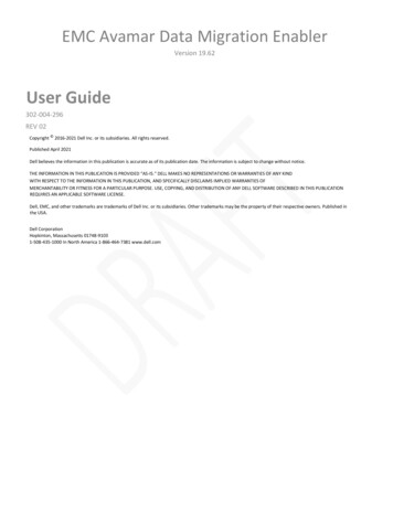
masterCONFIGURATOR manual 2.35 11-2021 en4 Active windowAfter starting up, the software displays the active window. The control gear and control units can be parameterised andconfigured here. Depending on the function, further sub-windows will be opened.NameFunction(1) Title barDisplays the name of the project file currently open.(2) Menu barContains the File, Settings, Commissioning, Tools and View menus.(3) ToolbarContains icons for quick access to various functions.iNoteYou can show or hide the toolbar via menu item View Toolbar.(4) DALI device tree diagramDisplays the devices connected to the DALI control line in a treediagram. It is also possible to see which group each device belongs to.(5) Detail viewDisplays the properties of a device or a group that has been selected inthe DALI device tree diagram. The devices or groups can be configuredand parametrised here.(6) Status barDisplays status information and help text.iNoteYou can show or hide the status bar via menu item View Status bar.Table 2: Active w indowc9
masterCONFIGURATOR manual 2.35 11-2021 en4 Active windowToolbarThe following icons are found in the toolbar:IconFunctionCreate a new projectOpen a projectSave a projectPrint a projectLocateIdentifyTable 3: ToolbariNoteA detailed description of the Locate and Identify functions can be found in Section Checkingdevice assignment. 35Changing the languageThe software user interface can be displayed in German or English. The language is changed as follows:1. Select View.2. Select language.A message appears indicating that the language will only be changed after the program has been restarted.Ü3. Confirm the message by clicking on OK.4. Restart the program.The software will be started in the desired language.ÜShowing/hiding advanced settingsControl gear and control units can be configured using the masterCONFIGURATOR. The advanced settings must bedisplayed in order to configure additional parameters as well as the general settings. The advanced settings can beshown or hidden as follows:1. Select View.2. Show (enable) or hide (disable) the Advanced settings.The advanced settings are shown/hidden in the detail view.Üc10
masterCONFIGURATOR manual 2.35 11-2021 en4 Active windowiNoteThe advanced settings must be enabled again each time the software is restarted.Update device listIf the Device Information of a Tridonic driver is not displayed correctly, it might be necessary to update the device list.To do so, click on the question mark and select the option Update Device list.A message will appear that the update was successful:c11
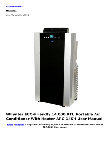
masterCONFIGURATOR manual 2.35 11-2021 en5 CommissioningThe masterCONFIGURATOR software allows the user to test the correct wiring of the DALI control line, address thedevices and define group and scene settings in five easy steps. In order for these steps to be carried out, an interfacemust first be selected. Optionally, the device search and the addressing can be narrowed down.5.1 Selecting an interfaceUse a DALI USB or the ready2mains Programmer for exchanging data between the computer and the devices on theDALI control line. For backward compatibility, DALI SCI2 can be used.iNoteDALI SCI is not supported.If the computer is already connected to the DALI control line via an interface, the masterCONFIGURATOR softwareautomatically detects the type of interface and selects it for communication. However, the interface may also beselected manually.Selecting an interface manually1. Connect the USB cable of the DALI USB or the ready2mains Programmer to the computer on which themasterCONFIGURATOR software is installed.2. Connect the DALI USB or the ready2mains Programmer to the DALI control line.3. Select Settings Select interface The Select interface pop-up window appears.Ü4. To use a USB interface, select the USB radio button and select the desired interface from the drop-down list.5. To use a COM interface, select the COM radio button and select the desired interface from the drop-down list.6. Confirm the selection by clicking on OK.The interface has been selected.DALI BusServer starts automatically.ÜÜc12
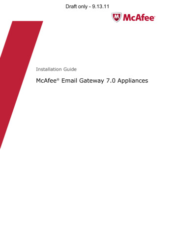
masterCONFIGURATOR manual 2.35 11-2021 en5 CommissioningiNoteIf the masterCONFIGURATOR software detects that a DALI USB is connected, itautomatically checks the USB software version. If it is older than the version supplied with themasterCONFIGURATOR software, it will be updated automatically. This update takesapproximately one minute.5.2 OptionsUnder Settings Options the following functions can be set:· Filter settings· eD addressing· Multimaster131417· Improvements185.2.1 Filter settingsThis function allows the user to narrow the device search or addressing.Enabling the filter1. Select Settings Options.The Options pop-up window appears.Ü2. Click on the Filter tab.3. Select the checkbox to include devices in the device search and addressing.4. Confirm the selection by clicking on OK.c13
masterCONFIGURATOR manual 2.35 11-2021 en5 CommissioningÜ Filter for the device search and the addressing is enabled.Ü Only those devices with enabled checkboxes will be included in the device search and the addressing.5.2.2 eDALI addressingUp to 64 eD addresses can be assigned when addressing eD devices. The 64 eD addresses can be configured to beassigned once per DALI control line or once per device class.Disabling the option1. Select Settings Options.The Options pop-up window appears.Ü2. Click on the eD addressing tab.3. Disable the checkbox.4. Confirm the selection by clicking on OK.The type of eD addressing has been changed. This change will be applied when the system is next re-initialised(New initialisation).ÜBoth types of eD addressing are explained in the following examples.· Example 1: Assign eD address (0-63) only once enabled:The eD addresses are assigned once per DALI control line.· Example 2: Assign eD address (0-63) only once disabled:The eD addresses are assigned once per device class.c14
masterCONFIGURATOR manual 2.35 11-2021 en5 CommissioningExample 1: eD addresses assigned once per DALI control lineDevice classeD addressExplanationDALI MSensor: light sensoreA 0The first of 64 eD addresses has been assignedon this DALI control line.DALI MSensor: motion sensoreA 1The second of 64 eD addresses has beenassigned on this DALI control line.DALI MSensor: remote controleA 2The third of 64 eD addresses has been assignedon this DALI control line.DALI MCeA 3The fourth of 64 eD addresses has beenassigned on this DALI control line.Table 4: Example of eD addressing, option enabledIn this example a total of four out of 64 eD addresses have been assigned. Another 60 eD addresses can still beassigned on this DALI control line.c15
masterCONFIGURATOR manual 2.35 11-2021 en5 CommissioningExample 2: eD addresses assigned once per device classDevice classeD addressExplanationDALI MSensor: light sensoreA 0The first of 64 eD addresses has been assignedto the "Light sensor" device class.DALI MSensor: motion sensoreA 0The first of 64 eD addresses has been assignedto the "Motion sensor" device class.DALI MSensor: remote controleA 0The first of 64 eD addresses has been assignedto the "Manual control units" device class.DALI MCeA 1The second of 64 eD addresses has beenassigned to the "Manual control units" deviceclass.Table 5: Example of eD addressing, option disabledIn this example only one of the 64 eD addresses has been assigned to each of the "Light sensor" and "Motion sensor"device classes. Another 63 eD addresses can still be assigned to each device class. Two of the 64 eD addresses havebeen assigned to the "Manual control units" device class. Another 62 eD addresses can still be assigned to this deviceclass.c16
masterCONFIGURATOR manual 2.35 11-2021 en5 Commissioning5.2.3 MultimasterThis function is enabled by default and prevents control devices from transmitting frames during firmware updates. Withthis, it is possible to avoid conflicting commands from the masterCONFIGURATOR and other control devices via theDALI line.Disabling the option1. Select Settings Options.The Options pop-up window appears.Ü2. Click on the Multimaster tab.3. Disable the checkbox.4. Confirm the selection by clicking on OK.Set the masterCONFIGURATOR as multimaster head has been deactivated. This change will be applied whenthe system is next re-initialised (New initialisation).ÜBoth types of Multimaster are explained in the following examples.· Example 1: Set the masterCONFIGURATOR as multimaster head enabled:The masterCONFIGURATOR is set as multimaster head. Other control devices cannot transmit frames during afirmware update.· Example 2: Set the masterCONFIGURATOR as multimaster head disabled:Other control devices can transmit frames during a firmware update.c17
masterCONFIGURATOR manual 2.35 11-2021 en5 Commissioning5.2.4 ImprovementsThis function is enabled by default and allows the application to track information about the functions used.Disabling the option1. Select Settings Options.The Options pop-up window appears.Ü2. Click on the Improvements tab.3. Disable the checkbox.4. Confirm the selection by clicking on OK.Allow data tracking to improve user experience has been deactivated. This change will be applied when thesystem is next re-initialised (New initialisation).Üc18
masterCONFIGURATOR manual 2.35 11-2021 en5 Commissioning5.3 Testing the installationThis function allows the user to test the wiring of the installation.Testing the installation1. Select Commissioning 1. Test installation.The Execute test pop-up window appears.Ü2. Enter an interval between 1 and 10 seconds.3. Click on Start.The Start button changes into the Stop button.Once the test is started, the minimum level and maximum level commands are sent alternately to allluminaires on the DALI control line.ÜÜ4. Click
masterCONFIGURATOR manual 2.35 11-2021 en 5 2 Introduction c The masterCONFIGURATOR s