Transcription
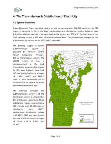
Integrated Resource Plan 20144. The Transmission & Distribution of Electricity4.1 System OverviewGreen Mountain Power provides electric service to approximately 260,000 customers in 202towns in Vermont. In 2013, the GMP transmission and distribution system delivered over4.3 million MWh of electricity; the peak load on the system was 762 MW. The backbone of theGMP delivery system is 976 miles of sub-transmission lines. The predominant voltages for thesubtransmission system are 34.5 kV, 46 kV, and 69 kV.The primary supply to GMP’ssubtransmissionsystemisprovided by Vermont ElectricPowerCompany’s(VELCO’s)115 kV transmission system. TheVELCO system, in turn, isinterconnected to the bulktransmission systems administeredby ISO New England, New YorkISO, and Hydro-Québec at voltagesof 115 kV, 230 kV, and 345 kV.GMP is also interconnected toNational Grid in several locationsat subtransmission voltages.The interface between thesubtransmission system and thedistribution system is comprised of147 distribution substations. Thesesubstations supply approximately300 circuits and 11,300 miles ofdistributionlines.GMP’spredominant distribution voltageis 12.47 kV. GMP also has a limitedamount of distribution at voltagesof 2.4 kV, 4.16 kV, 8.3 kV, and34.5 kV.Page 4-1
Integrated Resource Plan 20144.2 System Planning and Efficiency InitiativesTransmission and Distribution Planning CriteriaSubtransmissionGMP’s standard subtransmission voltages are 34.5 kV, 46 kV and 69 kV. Using thesubtransmission system, GMP transmits power from VELCO and National Grid delivery points toGMP’s distribution substations, wholesale customers, and large industrial customers. Thesubtransmission system is planned according to the Equal Slope Criteria. The Equal SlopeCriteria, discussed in detail in Appendix A, can be described as a modified N-1 criterion in whicha reasonable balance is sought between the total costs of a given solution and the total benefitsachieved. The goal is to achieve most of the benefit of adhering to a strict N-1 criterion but atsubstantially less cost. GMP’s operating criteria require system voltage to be between 95% and105% of nominal on the subtransmission system during all-lines-in operation and between 90%and 110% of nominal following a first contingency. Each element in the power delivery systemhas a thermal design load limit reflecting the load at which an element begins to overheat andfail. GMP applies a 100% maximum load limit on all elements during normal operation. Forspecific cases for limited periods of time during first contingency operation, we allowoverloading, but only with the understanding that operators will take quick action to remedythe overload by any means necessary, including the use of load shedding. This criterion foroverloading is explained further in Appendix A.DistributionGMP’s standard distribution system voltage is 12.47 kV/7.2 kV grounded wye1. We also employa limited amount of 34.5 kV/19.9 kV distribution system facilities, but because of operatingchallenges with 34.5 kV equipment we restrict the expansion of this voltage to areas where34.5 kV distribution has already been established. A limited amount of 2.4 kV, 4.16 kV, and8.3 kV distribution remains on the system; however we are steadily converting these voltagesto the standard 12.47 kV to improve voltage performance, reduce losses, accommodate loadgrowth, and permit feeder backup between substations. The voltage delivered to customersadheres to the standards prescribed by the American National Standards Institute (ANSI)Standard C84.1.1A wye is a three phase, four-wire electrical configuration where each of the individual phases is connectedto a common point, the “center” of the Y. This common point normally is connected to an electrical ground.Page 4-2
Integrated Resource Plan 2014System MonitoringThere are a number of data sources that are used by GMP to effectively monitor thesubtransmission and distribution system. This information is used to make decisions regardingtransferring load between circuits, removing substation banks for maintenance, correcting outof-standard voltages, interconnection of distributed generation, and addressing load growth inpotentially constrained areas. This information can dictate where area studies will be neededand provides insight into areas where non-transmission alternatives may be effective indeferring capital upgrades. The information used to monitor the system includes: Observations by line workers and substation technicians in the course of their dailyduties. The VELCO Long-Range Transmission Plan, which is updated every three years andidentifies portions of the GMP subtransmission system that could violatesubtransmission planning criteria considering forecasted load growth over the next 20years. Line and equipment loading obtained from GMP’s supervisory control and dataacquisition (SCADA) database. This database contains real power, reactive power, thestatus of capacitor banks, and phase unbalance data for the majority of oursubtransmission lines and a number of our distribution feeders. SCADA data is essentialin calibrating transmission and subtransmission load flow models that are used inplanning studies. Substation and circuit MV90 data, which includes real and reactive load and voltagedata for substations and individual circuits. Selected substations have per phasemetering to further enhance the understanding of critical circuit loading. Additional monitoring equipment, including thermal demand ammeters and revenuemeters, for those distribution feeders that are not monitored by SCADA or MV90. Customer interval load data is presently available for a number of customers. Throughthe use of AMI, GMP’s goal is to have interval load data available for all customers.Customer interval load data can be combined with load data from other sources to helpdetermine spatial loading of a circuit at a given point in time.Page 4-3
Integrated Resource Plan 2014 New relays, such as the Schweitzer SEL‐351, collect and store data including per phasecurrent, voltage, real power, reactive power, and neutral currents. These relays havebeen installed at a number of substations and their data can be retrieved as needed. Load loggers are portable devices that attach to an individual phase wire and recordcurrent flow in 1, 5, or 15 minute intervals. These devices are useful for analyzing phasebalancing and determining spatial load distribution across a given circuit. Tong tests are instantaneous current readings taken with a recording ammeter. Tongtesting is useful for balancing loads and verifying load estimates. This information isoften used when doing planned outage analyses. Per Act 250, developers planning new load additions greater than 100 kW must submitan Ability-to-Serve request to GMP. These requests are reviewed to ensure that the T&Dsystem can accommodate the proposed new load. All requests are stored in a database,and review of these proposed load additions and their respective analyses can providean indication of system adequacy and the potential for future constraints. Outage history and outage analyses, including identification of distribution feeders withthe poorest reliability performance, are helpful in identifying system problems. Similarly,customer complaints, such as those involving reliability concerns, low voltage, andvoltage flicker are valuable in identifying system weaknesses. GMP’s geographic information system is used to locate aging infrastructure andequipment that may be in need of replacement. GMP is continuing to develop its advanced metering infrastructure (AMI) in whichmeters that collect large amounts of data are deployed at most customers’ serviceentrances. In the future, GMP will be able to collect, sort and utilize increasingly detaileddata, including energy use, real power, reactive power, and voltage levels for eachparticipating customer. This data will be stored in the meter data management system(MDMS). The MDMS integrates the capabilities of the advanced meters, and the largeamount of collected data, with GMP’s existing systems including the Customer Care andBilling (CC&B) system and the outage management (Responder) system. Efficient accessby the engineering team to the MDMS, via new reporting and analytic tools, will greatlyimprove the capability and response time required to analyze electric system issues.Whereas traditional distribution analysis required little more than summer peak loadPage 4-4
Integrated Resource Plan 2014simulations, the growing complexity and variance of the distribution system makes theability to efficiently calibrate load flow models even more important than in the past.These complexities are driven by customer loads, the marked increased in distributedgeneration interconnections, load management schemes, and automated protectionstrategies. The access to MDMS data will allow for the efficient and accuratedevelopment of an expanded “family” of distribution load models, including models forlight loads, post-sundown peak loads, winter peak loads, and intermediate shoulderloads. The current timeline for AMI development is to have all voltage and VARinformation reading into the MDMS by first quarter 2015. The remainder of 2015 will beused to retrieve, evaluate and correct the data. ORACLE’s DataRaker analytics platformwill be leveraged for analysis and reporting purposes in 2015 and 2016. A more detaileddescription of AMI and MDMS is included in Chapter 5 on GMP SmartPower.The Planning ProcessGMP conducts T&D system planning to assure that the electric system can deliver power to itscustomers safely and reliably while achieving a reasonable balance between costs and benefits.A number of efforts are required in the overall planning process. The three main steps inplanning include: Orientation: A system problem (or potential problem) is identified; information isgathered; coordination with likely stakeholders is organized and a study scope and timeline are identified. Study Development and Analysis: Necessary methods, tools and data requirements areidentified to solve the problem. Analysis such as loadflow simulation is used to betterunderstand system deficiencies. Alternative solutions are devised and studied usingloadflow analysis, engineering calculations, and economic analysis as appropriate. Decision Making and Action: Results are reviewed; conclusions are drawn; andrecommendations are made and supported. These recommendations, typically in theform of a proposed project, may require various regulatory approvals. After allapprovals are secured, the project is implemented.Generally speaking, there are three main drivers behind system planning: efficiency, reliabilityand growth. As illustrated by the individual projects discussed later in this chapter, manyplanning exercises encompass all three. Planning also includes consideration of nontransmission alternatives (NTAs). As discussed below, GMP’s planning considers NTAs through apublic process directed by the Vermont System Planning Committee (VSPC).Page 4-5
Integrated Resource Plan 2014The T&D Planning process also recognizes that the performance of the transmission,subtransmission, and distribution systems are highly interdependent and cannot be viewed inisolation. In order to develop effective, least-cost plans, close coordination among thesesuccessive electric system levels is required. Planning coordination is discussed further below.GMP has 147 distribution substations supplying over 300 distribution circuits. Ideally, anintegrated and comprehensive efficiency study would be performed periodically on everycircuit. Unfortunately, it would not be a cost effective use of GMP’s limited resources toperform this level of detailed analysis for every location on the GMP system. In order to providethe maximum benefit for its customers, GMP uses available system data and screeningmethodologies to identify those areas that would most benefit from an in-depth examination ofadequacy and efficiency improvements. These screenings identify circuits that have potentialthermal or voltage constraints, inadequate power factors, phase imbalances, relay pickupoverloads, or that otherwise do not meet GMP’s planning criteria. Many of these overallanalyses require manual review of system data and the creation of numerous reports that aregenerated from multiple databases. Comprehensive system screenings are done on differenttimelines. For example, peak load reviews for all substations and circuits are typically done onan annual basis, whereas an overall review of all circuits’ power factor performance or phaseimbalance would be done less often. If an individual circuit experiences a significant change,such as additional load, substantial distributed generation, or reconfiguration, then it would beflagged for review for efficiency opportunities.By focusing on the identified circuits, GMP is able to find those areas that would most benefitfrom efficiency improvements. All subsequent analyses for the purpose of addressing capacity,reliability, and asset management inadequacies also incorporate a review of loss-avoidanceopportunities, including capacitor placement, reconductoring, voltage conversion, feederbalancing, and circuit reconfiguration. This strategy helps GMP direct its limited resourcestowards those circuits most in need of upgrades and most likely to provide cost effectiveopportunities for efficiency upgrades.GMP uses a number of strategies to screen circuits, including peak load reviews for substationsand circuits. GMP is presently integrating a number of data resources into a single, companywide ORACLE database known as the business intelligence (BI) tool. The BI tool combines thesedata sources and allows for the development of custom reports to streamline the screeningprocess. The BI tool will also permit GMP to decommission numerous small databases anddisparate reports while providing for a standardized and unified system of record. Thedevelopment of BI reporting for transmission and distribution planning is budgeted for 2015.GMP is also implementing ORACLE’s DataRaker. DataRaker is a cloud-based analytics platformthat will allow GMP to leverage vast amounts of its AMI data to optimize operationalPage 4-6
Integrated Resource Plan 2014performance and to transform GMP’s voluminous AMI data into meaningful and usefulinformation for business analysis. It is GMP’s goal to utilize BI reporting and DataRaker analyticsto provide automated screening for all of its substations and circuits. The current timeline hasthe development of automated screening beginning in 2016.Planning CoordinationVELCO and the Vermont System Planning CommitteeGMP participates with the Vermont Electric Power Company (VELCO) and the other Vermontdistribution utilities in planning the Vermont transmission system. In 2005, the Vermontlegislature amended the laws governing electric utility planning. Specifically, 30 V.S.A. § 218c(d)requires that every three years VELCO, in coordination with Vermont’s distribution utilities,develop a transmission plan (the Vermont Long‐Range Transmission Plan) that: Identifies existing and potential transmission system reliability deficiencies by locationwithin Vermont; Estimates the date, and identifies the local or regional load levels and other likelysystem conditions at which these reliability deficiencies, in the absence of furtheraction, would likely occur; Describes the likely manner of resolving the identified deficiencies through transmissionsystem improvements; Estimates the likely cost of these improvements; Identifies potential obstacles to the realization of these improvements; and Identifies the demand or supply parameters that generation, demand response, energyefficiency or other non-transmission strategies would need to resolve the reliabilitydeficiencies identified.30 V.S.A. § 218c(d) also establishes requirements for notice and public input regarding thedevelopment of the Long-Range Transmission Plan, requires that distribution utilitiesincorporate the most recently filed transmission plan in their individual least-cost integratedplanning processes, and mandates that VELCO and the distribution utilities cooperate asnecessary to develop and implement joint least-cost solutions to reliability deficienciesidentified in the Long-Range Transmission Plan.Page 4-7
Integrated Resource Plan 2014In 2007, in the context of Docket No. 7081, the Public Service Board developed a process forsatisfying these planning requirements and established the Vermont System PlanningCommittee (VSPC). The VSPC is the body responsible for implementing the planning processand is comprised of VELCO, Vermont’s electric distribution utilities, public members, andmembers representing supply and demand resources. The goal of the planning process is toensure the full, fair and timely consideration of all options to solve grid reliability in a mannerthat is transparent and public. Ultimately, the VSPC allows Vermont’s electric utilities to fulfillthe public policy goal behind 30 V.S.A. § 218c(d), namely that the most cost effective solutiongets chosen, whether it is a traditional transmission upgrade, energy efficiency, demandresponse, generation, or a hybrid solution. As part of this process, the VSPC coordinates withstakeholders at the local, state and regional levels. These stakeholders include ISO NewEngland, which has the primary responsibility for transmission planning in the region; regionalplanning commissions; local energy committees; Vermont’s energy efficiency utility (EEU); andVermont’s Sustainably Priced Energy Development (SPEED) facilitator.The transmission planning process, as approved by the Public Service Board and implementedby the VSPC, is comprised of the following steps: Step 1: VELCO performs a transmission analysis and creates a draft plan. Thistransmission analysis is closely coordinated with ISO New England and considers atwenty-year horizon. The analysis also identifies deficiencies with subtransmissionsystems owned and operated by the distribution utilities. Step 2A: The VSPC reviews the draft plan and makes a preliminary determination of theutilities impacted by reliability deficiencies. Step 2B: Distribution utilities and VELCO determine the applicable reliability criteria foreach reliability deficiency, identify transmission solutions, and determine the nontransmission alternative equivalence. Step 3A: VELCO conducts a preliminary NTA analysis for bulk transmission systemreliability deficiencies where appropriate. Step 3B: Distribution utilities together with VELCO conduct preliminary NTA analyses forsubtransmission system deficiencies where appropriate. Step 4: VELCO releases a draft Long-Range Transmission Plan.Page 4-8
Integrated Resource Plan 2014 Step 5: The draft Long-Range Transmission Plan is subject to a statewide publicinvolvement process. Step 6: VELCO with the VSPC publish the Long-Range Transmission Plan. Step 7: For each reliability deficiency or group of deficiencies, the VSPC refines theimpacted utilities determinations. Step 8: For each reliability deficiency or group of deficiencies, the affected utilities,VELCO, and the VSPC engage in a public involvement process and perform the requireddetailed NTA Analysis. Step 9: For each reliability deficiency or deficiencies, the affected utilities, VELCO, andthe VSPC, based on the results of the public involvement process, select a solution anddetermine cost allocation among the parties. Step 10: VELCO updates the Long-Range Transmission Plan.Page 4-9
Integrated Resource Plan 2014These steps are summarized in the following flow chart:Figure 4.2.1: Flow Chart of Planning CoordinationThe status of GMP’s projects subject to the VSPC process is contained in the VSPC 2014 AnnualReport to the Public Service Board and Public Service Department, February 14, 2014 and isattached as Appendix B.The Consideration of Standard Offer Projects to Address Reliability ConstraintsIn 2012, the Vermont General Assembly passed Act 170 mandating certain changes to theSustainably Priced Energy Enterprise Development (SPEED) standard offer program, pursuant to30 V.S.A. §§ 8005a and 8006a. Among these changes is the exclusion from cumulative plantcapacity of new standard offer plants that provide sufficient benefits to the operation andmanagement of the electric grid. By orders in Docket Nos. 7873 & 7874, the Board adoptedscreening framework and guidelines that provide potential standard offer project developerswith information on transmission and distribution constrained areas in which renewablegeneration may resolve the constraints. The Board-approved screening framework andguidelines uses VSPC processes, reporting mechanisms, and subcommittees to identify andPage 4-10
Integrated Resource Plan 2014resolve T&D constraints via NTAs, including standard offer projects. These processes analyzethe electric grid for reliability gaps, make recommendations to the Board regarding thepotential for NTAs to mitigate those reliability gaps, provide stakeholders with the opportunityto comment on the VSPC recommendations, and result in Board decisions on whether an RFPwill be issued for new standard-offer plants.GMP has been an active participant in the VSPC processes outlined above. Since the adoption ofthe screening framework and guidelines, GMP has brought forward no fewer than 17transmission and distribution constraints to the VSPC Geotargeting Subcommittee, and the fullVSPC, for consideration and review. Among these constraints, two have been determined bythe VSPC to be potentially resolvable through the use of NTAs, namely the St. Albans area andthe Rutland area. Consistent with the above outlined processes, a reliability plan was developedfor the St. Albans area and was provided to the Board and interested parties in April 2014. GMPanalysis shows that the need date, even under a very aggressive growth scenario, is not until2021. Even under this scenario, it is unlikely that major upgrades would be required to addressthe deficiency. As such, GMP is continuing to monitor the area. A preliminary reliability planfor the Rutland area was also filed in April 2014 and further analysis is currently underway thatmay reveal the potential for cost-effectively addressing the reliability gap with somecombination of targeted energy efficiency, demand response, battery storage, or distributedgeneration. GMP expects to file its updated reliability plan in April 2015.Other Electric UtilitiesGMP regularly communicates and coordinates with other electric utilities to share informationand develop system upgrades that can benefit one or the other utility. Examples of thiscoordination include the following: GMP is collaborating with the Vermont Electric Cooperative (VEC) in the Hinesburg areato relieve high loads on the GMP system. Specifically, a new 12.47 kV distribution feederis under construction that will originate at the VEC Rhode Island Corners substation andextends into Hinesburg to supply GMP load and relieve loading on a long feeder thatoriginates at the GMP Charlotte substation and extends over eight miles into Hinesburg. Similarly, GMP has an agreement with VEC in which VEC supplies the GMP load in theSheldon area in the short term to relieve a reliability exposure on GMP’s area 34.5 kVsubtransmission system. GMP will resume supply to its Sheldon load followingcompletion of the Georgia Interconnection Project, described in detail below under theheading Projects Completed or Under Construction.Page 4-11
Integrated Resource Plan 2014 GMP is working the Burlington Electric Department (BED) to transfer ownership of arecently disconnected GMP subtransmission line to BED. This transfer of assets wouldprovide BED with the opportunity to develop a low-cost express feeder from its QueenCity substation into the downtown Burlington area. This arrangement would also benefitGMP by allowing GMP to avoid the expense of retiring and removing this line. GMP provides bulk power, operational services, and engineering services to the Villageof Jacksonville Electric Department (Jacksonville) and to the Northfield ElectricDepartment. GMP recently collaborated with Jacksonville to study the feasibility of aproposed 150 kW solar installation in the Jacksonville service territory. GMP is supplied by the National Grid subtransmission system at several interconnectionpoints throughout the system. On an annual basis, GMP provides National Grid withload forecasts and power factor data to assist National Grid in fulfilling certain ISO NewEngland planning and reporting requirements. GMP is working with the Village of Ludlow Electric Department (Ludlow) to develop aprimary-metered delivery point that would be connected to the Ludlow system for thepurpose of supplying a proposed ski lift located within GMP’s service territory. Thisstrategy avoids the need for GMP to upgrade several miles of single phase line to threephase line in its territory, lowers the cost to the customer, and helps the customer meetits project timelines. GMP is also collaborating with Ludlow on future configurations tosupply expanding loads on the Ludlow system. These collaborations lower the overallcost of service for both utilities and optimize the use of existing distribution facilities.Conservation Voltage RegulationConservation Voltage Regulation (CVR) is an energy efficiency program applied to an electricutility’s distribution system, involving measures and operating strategies designed to provideservice at the lowest practicable voltage level in a cost-effective manner, while meeting allapplicable voltage standards. Field studies have shown that, in general, a one percent reductionin the voltage delivered to customers results in a one percent reduction in energy consumption.To date, the primary strategy for implementing CVR has been the use of line dropcompensation (LDC). LDC is a control device connected to tap-changing transformers andvoltage regulators that measures feeder load current and computes the resultant voltage drop.The value of the voltage drop is then used by the tap changer or regulator to raise or lower thefeeder voltage.Page 4-12
Integrated Resource Plan 2014GMP supplies service voltage to its residential customers at 120 volts nominal with a range of 5% to -5% as required by ANSI Standard C84.1-2011. CVR has been implemented on a numberof circuits for both the legacy GMP and legacy CVPS portions of the distribution system. On thelegacy GMP system, the CVR strategy has been to use LDC to keep the end-of-feeder voltage aslow as possible while maintaining this voltage at or above 114 Volts (i.e., 120 Volts -5%). On thelegacy CVPS system, the CVR strategy has been to reduce the maximum service voltage by 2%resulting in a compressed service voltage range of 3% to -5% with 120 Volts nominal. This isaccomplished by changing the central mean voltage (CMV) settings on distribution substationand line regulators from 122 volts to 120 volts.Not all circuits are appropriate for the implementation of CVR. These can include long circuits,circuits in which voltage regulation occurs at the substation bus, and circuits with largecommercial and industrial loads in which customers provide their own voltage regulation. Somecircuits that were previously on CVR have been removed from CVR to allow for circuit transfersduring planned or contingency situations or because of complaints from sensitive customers.An emerging issue with CVR pertains to the installation of distributed generation on thedistribution system. Large quantities of generation on a distribution feeder reduces the amountof current that LDC controls can detect, thereby reducing the apparent voltage drop across thelength of the feeder and resulting in low voltages delivered to customers at the ends of feeders.GMP believes that, moving forward, further development of CVR should take advantage of thematuring advanced metering infrastructure (AMI) program. Among the strategies available withAMI is the integrated Volt/VAR control (IVVC) of distribution circuits. IVVC is a control strategyin which distribution circuit voltages along a given circuit are measured in real time. Thesevoltage measurements are then used to optimize voltage regulator settings and capacitor bankswitching. An IVVC pilot program will be conducted in 2015 and 2016 as part of GMP’s RutlandGrid Innovation project. This pilot program, together with the potential for the expansion ofIVVC to other parts of the GMP system, is discussed further below under the headingDistribution Automation and System Management / The Rutland Grid Innovation Project.Power Factor CorrectionAppropriate reactive power (VAR) compensation through the placement of capacitors allowsfor a more efficient and less costly power delivery system and can reduce or postponeinvestments in system facilities. The majority of capacitor placements on the GMP system takeplace at the distribution level. To maximize benefits, it is generally best to correct reactivepower flow closest to the load. When this is accomplished, efficiency opportunities aremaximized through the use of lower voltage distribution capacitors that are generally lessPage 4-13
Integrated Resource Plan 2014expensive than higher voltage subtransmission capacitor banks. The close placement of VARsources to loads also reduces losses. In addition, ISO New England strictly limits reactive powerflow between reliability regions. ISO New England requires that VELCO hold its transmissionsystem power factor to no less than 0.98. In turn, VELCO limits the power factor at GMP’sdelivery points to no less than 0.95. GMP calculates power factor using real and reactive powerobtained from GMP’s supervisory control and data acquisition (SCADA) database and fromsubstation and circuit MV90 data.To help meet
4.1 System Overview Green Mountain Power provides electric service to approximately 260,000 customers in 202 towns in Vermont. In 2013, the GMP transmission and distribution system delivered over 4.3 million MWh of electricity; the peak load on the system was 762 MW. The backbone of the GMP delivery