Transcription
PLUMBING SYSTEMSPLUMBING DESIGNA S S I S TA N C E M A N U A L(PDAM)Uponor Plumbing DesignAssistance Manual (PDAM)
Plumbing Design Assistance Manualis published byUponor, Inc.5925 148th Street WestApple Valley, MN 55124 USATel: 800.321.4739Fax: or Ltd.2000 Argentia Rd., Plaza 1, Ste. 200Mississauga, ON L5N 1W1 CANADATel: 888.994.7726Fax: 800.638.9517uponorpro.comuponorengineering.com 2015 UponorAll rights reserved.Fourth EditionFirst Printing March 2008Printed in the United States of AmericaUponor has used reasonable efforts in collecting, preparingand providing quality information and material in this manual.However, system enhancements may result in modification offeatures or specifications without notice.Uponor is not liable for installation practices that deviate fromthis manual or are not acceptable practices within the mechanical trades.iiuponorengineering.com
Table of ContentsPlumbing Design Assistance ManualForeword. . . . . . . . . . . . . . . . . . . . . . . . . . . . . . . . . . . . . . . . . . . . . . . . . . . . . . . . . . . . viiChapter 1: Uponor PEX Properties. . . . . . . . . . . . . . . . . . . . . . . . . . . . . . . . . . . . . . . . 1Uponor PEX Properties. . . . . . . . . . . . . . . . . . . . . . . . . . . . . . . . . . . . . . . . . . . . . . . . . 1PEX-a Distinctions. . . . . . . . . . . . . . . . . . . . . . . . . . . . . . . . . . . . . . . . . . . . . . . . . . . . 1Stress Resistance . . . . . . . . . . . . . . . . . . . . . . . . . . . . . . . . . . . . . . . . . . . . . . . . . . . . . 1Cleanliness of Uponor PEX. . . . . . . . . . . . . . . . . . . . . . . . . . . . . . . . . . . . . . . . . . . . . . 1Ultraviolet (UV) Resistance . . . . . . . . . . . . . . . . . . . . . . . . . . . . . . . . . . . . . . . . . . . . . 2Chemical Resistance. . . . . . . . . . . . . . . . . . . . . . . . . . . . . . . . . . . . . . . . . . . . . . . . . . . 2Oxidative Resistance . . . . . . . . . . . . . . . . . . . . . . . . . . . . . . . . . . . . . . . . . . . . . . . . . . 2Hydrostatic Temperature and Pressure Ratings . . . . . . . . . . . . . . . . . . . . . . . . . . . . . . 3Interpolation Method. . . . . . . . . . . . . . . . . . . . . . . . . . . . . . . . . . . . . . . . . . . . . . . . . . 3Excessive Temperature and Pressure Capability. . . . . . . . . . . . . . . . . . . . . . . . . . . . . . 3Standards, Codes and Listings . . . . . . . . . . . . . . . . . . . . . . . . . . . . . . . . . . . . . . . . . . . 4ProPEX Fittings. . . . . . . . . . . . . . . . . . . . . . . . . . . . . . . . . . . . . . . . . . . . . . . . . . . . . . 5Uponor ProPEX Engineered Polymer (EP) Fittings. . . . . . . . . . . . . . . . . . . . . . . . . . . . 5The Strength of Uponor EP . . . . . . . . . . . . . . . . . . . . . . . . . . . . . . . . . . . . . . . . . . . . . 6Uponor ProPEX Lead-free (LF) Brass Fittings . . . . . . . . . . . . . . . . . . . . . . . . . . . . . . . 6Fittings by Others . . . . . . . . . . . . . . . . . . . . . . . . . . . . . . . . . . . . . . . . . . . . . . . . . . . . 6Chapter 2: Making ProPEX Connections. . . . . . . . . . . . . . . . . . . . . . . . . . . . . . . . . . . . 7General ProPEX Connection Tips. . . . . . . . . . . . . . . . . . . . . . . . . . . . . . . . . . . . . . . . . 7Distance Between Fittings . . . . . . . . . . . . . . . . . . . . . . . . . . . . . . . . . . . . . . . . . . . . . . 7Making ProPEX Connections with Milwaukee M12 and M18 ProPEX Expansion Tools. . . . . . . . . . . . . . . . . . . . . . . . . . . . . . . . . 8Making ProPEX Connections with the MilwaukeeM18 FORCELOGIC ProPEX Expansion Tool. . . . . . . . . . . . . . . . . . . . . . . . . . . . . . . 10Making ProPEX Connections with the ProPEX 201 Corded Expander Tool. . . . . . . . 12Making ProPEX Connections with the ProPEX Hand Expander Tool. . . . . . . . . . . . . 14Making 3 8" ProPEX Connections . . . . . . . . . . . . . . . . . . . . . . . . . . . . . . . . . . . . . . . . 16Proper Expander Tool and Head Maintenance. . . . . . . . . . . . . . . . . . . . . . . . . . . . . . 16Disconnecting a ProPEX Brass Fitting . . . . . . . . . . . . . . . . . . . . . . . . . . . . . . . . . . . . 17Troubleshooting ProPEX Connections . . . . . . . . . . . . . . . . . . . . . . . . . . . . . . . . . . . . 18Chapter 3: Fire-resistant Construction. . . . . . . . . . . . . . . . . . . . . . . . . . . . . . . . . . . . 19Wood-frame Assemblies. . . . . . . . . . . . . . . . . . . . . . . . . . . . . . . . . . . . . . . . . . . . . . . 19Wood-frame Floor/Ceiling Assemblies. . . . . . . . . . . . . . . . . . . . . . . . . . . . . . . . . . . . 19Steel/Concrete Wall Assemblies. . . . . . . . . . . . . . . . . . . . . . . . . . . . . . . . . . . . . . . . . 20Steel/Concrete Floor/Ceiling Assemblies. . . . . . . . . . . . . . . . . . . . . . . . . . . . . . . . . . 20Wood-frame Assemblies (U.S.). . . . . . . . . . . . . . . . . . . . . . . . . . . . . . . . . . . . . . . . . . 21Wood-frame Assemblies (Canada) . . . . . . . . . . . . . . . . . . . . . . . . . . . . . . . . . . . . . . . 23Concrete Assemblies (U.S.). . . . . . . . . . . . . . . . . . . . . . . . . . . . . . . . . . . . . . . . . . . . . 25Plumbing Design Assistance Manual—Table of Contentsiii
Table of ContentsPlumbing Design Assistance ManualConcrete Assemblies (Canada). . . . . . . . . . . . . . . . . . . . . . . . . . . . . . . . . . . . . . . . . . 26ASTM E814 or CAN/ULC-S115 . . . . . . . . . . . . . . . . . . . . . . . . . . . . . . . . . . . . . . . . . 27Fire Stopping Solutions . . . . . . . . . . . . . . . . . . . . . . . . . . . . . . . . . . . . . . . . . . . . . . . 27Cast-in-place Sleeves. . . . . . . . . . . . . . . . . . . . . . . . . . . . . . . . . . . . . . . . . . . . . . . . . 29ASTM E84 — Surface Burning Characteristics (U.S.). . . . . . . . . . . . . . . . . . . . . . . . . 30CAN/ULC-S102.2 — Surface Burning Characteristics (Canada). . . . . . . . . . . . . . . . . 32Underwriters Laboratories (UL) 2846. . . . . . . . . . . . . . . . . . . . . . . . . . . . . . . . . . . . . 35Chapter 4: Pipe Sizing. . . . . . . . . . . . . . . . . . . . . . . . . . . . . . . . . . . . . . . . . . . . . . . . . 37Standard Dimension Ratio . . . . . . . . . . . . . . . . . . . . . . . . . . . . . . . . . . . . . . . . . . . . . 37Temperature and Pressure Ratings. . . . . . . . . . . . . . . . . . . . . . . . . . . . . . . . . . . . . . . 37Pipe Sizing an Uponor AquaPEX Plumbing System . . . . . . . . . . . . . . . . . . . . . . . . . . 37Uniform Friction Loss Method. . . . . . . . . . . . . . . . . . . . . . . . . . . . . . . . . . . . . . . . . . 39Uponor AquaPEX Design Parameters. . . . . . . . . . . . . . . . . . . . . . . . . . . . . . . . . . . . . 41Friction Loss with Uponor PEX Piping . . . . . . . . . . . . . . . . . . . . . . . . . . . . . . . . . . . . 42Darcy-Weisbach Method . . . . . . . . . . . . . . . . . . . . . . . . . . . . . . . . . . . . . . . . . . . . . . 42Hazen-Williams Method. . . . . . . . . . . . . . . . . . . . . . . . . . . . . . . . . . . . . . . . . . . . . . . 43Comparing Darcy-Weisbach and Hazen-Williams. . . . . . . . . . . . . . . . . . . . . . . . . . . . 44Friction Loss of Fittings . . . . . . . . . . . . . . . . . . . . . . . . . . . . . . . . . . . . . . . . . . . . . . . 44The Cv Method for Calculating Friction Loss . . . . . . . . . . . . . . . . . . . . . . . . . . . . . . . 45UPC Table 610.4. . . . . . . . . . . . . . . . . . . . . . . . . . . . . . . . . . . . . . . . . . . . . . . . . . . . . 46IPC Table E201.1 . . . . . . . . . . . . . . . . . . . . . . . . . . . . . . . . . . . . . . . . . . . . . . . . . . . . 47NPCC Table A-2.6.3.1(2)A. . . . . . . . . . . . . . . . . . . . . . . . . . . . . . . . . . . . . . . . . . . . . 49NPCC Table 2.6.3.2 . . . . . . . . . . . . . . . . . . . . . . . . . . . . . . . . . . . . . . . . . . . . . . . . . . 50Chapter 5: System Design and Layout . . . . . . . . . . . . . . . . . . . . . . . . . . . . . . . . . . . . 53The Uponor Advantage . . . . . . . . . . . . . . . . . . . . . . . . . . . . . . . . . . . . . . . . . . . . . . . 53Unit/In-suite Piping. . . . . . . . . . . . . . . . . . . . . . . . . . . . . . . . . . . . . . . . . . . . . . . . . . 53Uponor Logic Plumbing. . . . . . . . . . . . . . . . . . . . . . . . . . . . . . . . . . . . . . . . . . . . . . . 54Efficiencies of Uponor Logic. . . . . . . . . . . . . . . . . . . . . . . . . . . . . . . . . . . . . . . . . . . . 55Hot-water Performance . . . . . . . . . . . . . . . . . . . . . . . . . . . . . . . . . . . . . . . . . . . . . . . 55Reverse Osmosis and De-ionized Water Systems. . . . . . . . . . . . . . . . . . . . . . . . . . . . 56Surge Pressure and Sound Intensity. . . . . . . . . . . . . . . . . . . . . . . . . . . . . . . . . . . . . . 56Water Hammer. . . . . . . . . . . . . . . . . . . . . . . . . . . . . . . . . . . . . . . . . . . . . . . . . . . . . . 56Water Hammer Arrestors. . . . . . . . . . . . . . . . . . . . . . . . . . . . . . . . . . . . . . . . . . . . . . . 56Commercial Flush Bank Detail . . . . . . . . . . . . . . . . . . . . . . . . . . . . . . . . . . . . . . . . . . 57Hot-water System Design. . . . . . . . . . . . . . . . . . . . . . . . . . . . . . . . . . . . . . . . . . . . . . 57Recirculated Hot-water Systems. . . . . . . . . . . . . . . . . . . . . . . . . . . . . . . . . . . . . . . . . 58Balancing of Recirculated Hot-water Systems . . . . . . . . . . . . . . . . . . . . . . . . . . . . . . 58Heat Trace . . . . . . . . . . . . . . . . . . . . . . . . . . . . . . . . . . . . . . . . . . . . . . . . . . . . . . . . . 58ivTable of Contents—uponorengineering.com
Table of ContentsPlumbing Design Assistance ManualThermal Conductivity. . . . . . . . . . . . . . . . . . . . . . . . . . . . . . . . . . . . . . . . . . . . . . . . . 58Insulation. . . . . . . . . . . . . . . . . . . . . . . . . . . . . . . . . . . . . . . . . . . . . . . . . . . . . . . . . . 58Pre-insulated Uponor AquaPEX Piping. . . . . . . . . . . . . . . . . . . . . . . . . . . . . . . . . . . . 59Uponor PEX vs. Copper Heat Loss Comparison — Btu/(hr ft). . . . . . . . . . . . . . . . . 59Uponor Ecoflex Products . . . . . . . . . . . . . . . . . . . . . . . . . . . . . . . . . . . . . . . . . . . . . 60Thermal Expansion and Contraction. . . . . . . . . . . . . . . . . . . . . . . . . . . . . . . . . . . . . . 61Chapter 6: Installation Methods. . . . . . . . . . . . . . . . . . . . . . . . . . . . . . . . . . . . . . . . . 67Local Code Approvals. . . . . . . . . . . . . . . . . . . . . . . . . . . . . . . . . . . . . . . . . . . . . . . . . 67Storing and Handling PEX . . . . . . . . . . . . . . . . . . . . . . . . . . . . . . . . . . . . . . . . . . . . . 67Uncoiling PEX . . . . . . . . . . . . . . . . . . . . . . . . . . . . . . . . . . . . . . . . . . . . . . . . . . . . . . 68Bending PEX . . . . . . . . . . . . . . . . . . . . . . . . . . . . . . . . . . . . . . . . . . . . . . . . . . . . . . . 68Reforming Kinked Piping . . . . . . . . . . . . . . . . . . . . . . . . . . . . . . . . . . . . . . . . . . . . . . 68Thawing Frozen Piping. . . . . . . . . . . . . . . . . . . . . . . . . . . . . . . . . . . . . . . . . . . . . . . . 68Supporting Uponor PEX Pipe . . . . . . . . . . . . . . . . . . . . . . . . . . . . . . . . . . . . . . . . . . 69Supporting Fittings and Valves. . . . . . . . . . . . . . . . . . . . . . . . . . . . . . . . . . . . . . . . . . 70Uponor PEX-a Pipe Support . . . . . . . . . . . . . . . . . . . . . . . . . . . . . . . . . . . . . . . . . . . 72Hanger and Support Layouts with PEX-a Pipe Support. . . . . . . . . . . . . . . . . . . . . . . 72General Requirements for PEX-a Pipe Support . . . . . . . . . . . . . . . . . . . . . . . . . . . . . 73Strapping Requirements for PEX-a Pipe Support. . . . . . . . . . . . . . . . . . . . . . . . . . . . 75ASTM E84 Requirements for PEX-a Pipe Support. . . . . . . . . . . . . . . . . . . . . . . . . . . 76Expansion and Contraction Control with PEX-a Pipe Support . . . . . . . . . . . . . . . . . . 76Supporting Uponor Multiport Tees. . . . . . . . . . . . . . . . . . . . . . . . . . . . . . . . . . . . . . . 77Vertical Support Requirements. . . . . . . . . . . . . . . . . . . . . . . . . . . . . . . . . . . . . . . . . . 79Support Methods. . . . . . . . . . . . . . . . . . . . . . . . . . . . . . . . . . . . . . . . . . . . . . . . . . . . 80Wood-frame Construction . . . . . . . . . . . . . . . . . . . . . . . . . . . . . . . . . . . . . . . . . . . . . 80Steel-frame Construction. . . . . . . . . . . . . . . . . . . . . . . . . . . . . . . . . . . . . . . . . . . . . . 81Expansion-compensating Devices. . . . . . . . . . . . . . . . . . . . . . . . . . . . . . . . . . . . . . . . 83Expansion and Contraction: Cold-water Risers. . . . . . . . . . . . . . . . . . . . . . . . . . . . . . 84Expansion and Contraction: Hot-water Risers . . . . . . . . . . . . . . . . . . . . . . . . . . . . . . 84Public-use Fixtures. . . . . . . . . . . . . . . . . . . . . . . . . . . . . . . . . . . . . . . . . . . . . . . . . . . 85Pipe Labels. . . . . . . . . . . . . . . . . . . . . . . . . . . . . . . . . . . . . . . . . . . . . . . . . . . . . . . . . 85Commercial Flush Bank Detail . . . . . . . . . . . . . . . . . . . . . . . . . . . . . . . . . . . . . . . . . . 85Under-slab/Below-grade Installation. . . . . . . . . . . . . . . . . . . . . . . . . . . . . . . . . . . . . 86Pre-insulated Uponor AquaPEX Piping. . . . . . . . . . . . . . . . . . . . . . . . . . . . . . . . . . . . 86Pre-sleeved Uponor AquaPEX Piping. . . . . . . . . . . . . . . . . . . . . . . . . . . . . . . . . . . . . 86Water Service Requirements. . . . . . . . . . . . . . . . . . . . . . . . . . . . . . . . . . . . . . . . . . . . 86Trace Wire . . . . . . . . . . . . . . . . . . . . . . . . . . . . . . . . . . . . . . . . . . . . . . . . . . . . . . . . . 87Trench Bottom Preparation . . . . . . . . . . . . . . . . . . . . . . . . . . . . . . . . . . . . . . . . . . . . 88Piping Embedment. . . . . . . . . . . . . . . . . . . . . . . . . . . . . . . . . . . . . . . . . . . . . . . . . . . 88Plumbing Design Assistance Manual—Table of Contentsv
Table of ContentsPlumbing Design Assistance ManualInstallation. . . . . . . . . . . . . . . . . . . . . . . . . . . . . . . . . . . . . . . . . . . . . . . . . . . . . . . . . 88Handling and Repairs. . . . . . . . . . . . . . . . . . . . . . . . . . . . . . . . . . . . . . . . . . . . . . . . . 88H-20 Loads . . . . . . . . . . . . . . . . . . . . . . . . . . . . . . . . . . . . . . . . . . . . . . . . . . . . . . . . 89Horizontal Directional Drilling (HDD). . . . . . . . . . . . . . . . . . . . . . . . . . . . . . . . . . . . . 89Criteria for Uponor PEX Piping in HDD Applications. . . . . . . . . . . . . . . . . . . . . . . . . 89Joining Methods and Fittings. . . . . . . . . . . . . . . . . . . . . . . . . . . . . . . . . . . . . . . . . . . 89Water System Disinfection . . . . . . . . . . . . . . . . . . . . . . . . . . . . . . . . . . . . . . . . . . . . . 90Pressure-testing Procedures. . . . . . . . . . . . . . . . . . . . . . . . . . . . . . . . . . . . . . . . . . . . 90Importance of Conditioning Uponor PEX Pipe. . . . . . . . . . . . . . . . . . . . . . . . . . . . . . 90Conditioning and Sustained Pressure Testing Procedure. . . . . . . . . . . . . . . . . . . . . . 90Insulation. . . . . . . . . . . . . . . . . . . . . . . . . . . . . . . . . . . . . . . . . . . . . . . . . . . . . . . . . . 91Icynene Spray Foam Insulation. . . . . . . . . . . . . . . . . . . . . . . . . . . . . . . . . . . . . . . . . 91Closed-cell Spray Foams. . . . . . . . . . . . . . . . . . . . . . . . . . . . . . . . . . . . . . . . . . . . . . . 91Recessed Light Fixtures . . . . . . . . . . . . . . . . . . . . . . . . . . . . . . . . . . . . . . . . . . . . . . . 91Painting Uponor AquaPEX. . . . . . . . . . . . . . . . . . . . . . . . . . . . . . . . . . . . . . . . . . . . . 92Termiticides/Pesticides . . . . . . . . . . . . . . . . . . . . . . . . . . . . . . . . . . . . . . . . . . . . . . . 92Appendix A: Fluid Properties . . . . . . . . . . . . . . . . . . . . . . . . . . . . . . . . . . . . . . . . . . . 93Appendix B: Uponor PEX Friction Loss Tables. . . . . . . . . . . . . . . . . . . . . . . . . . . . . . 95Appendix C: Fitting Equivalent Length. . . . . . . . . . . . . . . . . . . . . . . . . . . . . . . . . . . 105Appendix D: ProPEX Fitting Dimensions . . . . . . . . . . . . . . . . . . . . . . . . . . . . . . . . . 113Appendix E: Expansion Arm and Loop Calculations. . . . . . . . . . . . . . . . . . . . . . . . . 125Appendix F: Pipe Heat Loss and Surface Temperature. . . . . . . . . . . . . . . . . . . . . . 155viTable of Contents—uponorengineering.com
ForewordThis design assistance manual ispublished for architects, buildingofficials, engineers and mechanicalcontractors interested in UponorProfessional Plumbing Systems.It describes general installationrecommendations that useUponor AquaPEX pipingproducts. Refer to local codesfor additional requirements.Uponor is not liable for installationpractices that deviate from thismanual or are not acceptablepractices within the mechanicaltrades, codes or standards of practice.Refer to the Uponor AquaSAFETMInstallation Guide to install acombination plumbing and fire safetysystem using Uponor products.Uponor made reasonable effortsto collect, prepare and providequality information and materialin this manual. However, systemenhancements may result inmodification of features orspecifications without notice.Plumbing Design Assistance Manual—ForewordDirect any questions regardingthe suitability of an application ora specific design to a local Uponorrepresentative by calling toll free888.594.7726 (United States)or 888.994.7726 (Canada).Note that this manual isavailable in English, Spanishand French at no charge.To order additional copies, go touponorpro.com/pdam.vii
viiiuponorengineering.com
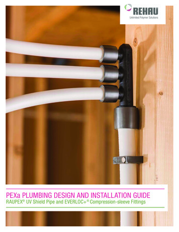
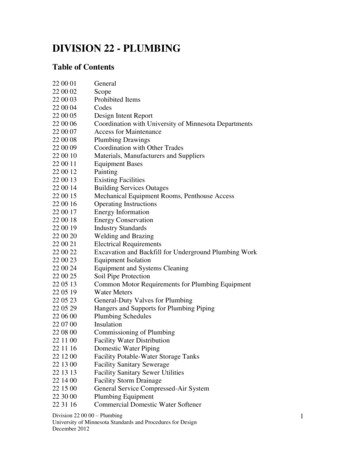
Chapter 1Uponor PEX PropertiesUponor PEX PropertiesPEX is an acronym for crosslinkedpolyethylene. The “PE” refers tothe raw material used to makepolyethylene; the “X” refers to thecrosslinking of the polyethyleneacross its molecular chains.The molecular chains are linkedinto a three-dimensional networkthat makes PEX remarkably durablewithin a wide range of temperaturesand pressures.Figure 1-1: PEX-a(Engel) 80% crosslinkedCurrently, three methods exist forproducing PEX. Engel or peroxide method (PEX-a) Silane method (PEX-b) Electron beam (e-beam) orradiation method (PEX-c)The pipe’s shape memory alsooffers the unique opportunity forProPEX fitting connections. Shapememory allows PEX-a to expand andthen shrink back to normal size —creating strong, durable and reliablefitting connections.Finally, PEX-a pipe offers moreresistance to crack propagation (howa crack grows) than PEX-b or PEX-cpipe. A crack that occurs in PEX-apipe is the least likely to grow overtime and cause leaks or damage.All three processes generate pipethat is crosslinked to various degreesaccording to ASTM F876 and F877standards.Uponor manufactures Engel-methodPEX-a pipe. The PEX industryconsiders this pipe superior becausethe crosslinking is done duringthe manufacturing process whenthe polyethylene is in its amorphicstate (above the crystalline meltingpoint). Accordingly, the degree ofcrosslinking reaches more than80%, resulting in a more uniformproduct with no weak links in themolecular chain.Stress ResistancePipe installed in commercialapplications must be capableof withstanding the stresses thatresult from installation withincommercial buildings.Typical stresses include: Expansion and contractionthat result from repeatedheating and subsequent coolingof the heat-transfer fluidPEX-a DistinctionsThe properties of PEX-a pipe make itthe most flexible PEX on the market.This flexibility allows the tightestbend radius available — six timesthe outside diameter of the pipe.Its flexibility also greatly reducesinstances of kinked pipe. And in therare instance of a kink, the thermalmemory of PEX-a allows kink repairwith a simple shot of heat from aheat gun.Plumbing Design Assistance ManualFigure 1-2: PEX-b(Silane) 65-70%crosslinked Mechanical abrasion, shearingand stretching that occurs asa result of installation, normalstructural movement and heatingand cooling from seasonalweather changesUponor PEX provides the durabilityand reliability that is needed for theseapplications and currently holds theunofficial world record for long-termtesting at elevated temperature—Chapter 1 – Uponor PEX PropertiesFigure 1-3: PEX-c(Radiation) 70-75%crosslinkedand pressure. From 1973 to 2009,the pipe was subjected to ongoingtesting at 203 F (95 C) at 175 psiby Studvik in Sweden and BASFin Germany.Cleanliness ofUponor PEXThe quality materials and exactingprocess used in manufacturingUponor AquaPEX yield remarkablyclean water-distribution piping.Uponor PEX piping is made bycrosslinking high-density,highmolecular weight, 100% virginpolyethylene flake. It is subject tothe highest testing, codes, listingsand standards.In addition to testing andcertification at NSF International,Canadian Standards Association(CSA) and Underwriters Laboratories(UL), Uponor PEX piping has beentested and approved for potablewater applications by the mostdemanding agencies in the world,including DVWG-Germany, KIWANetherlands, CTSB-France and BSIGreat Britain.Toxicity extraction testing performedin accordance with ANSI/NSF 61Drinking Water System Components— Health Effects verifies UponorPEX piping does not leachpotentially harmful substancesinto the drinking water.1
Ultraviolet (UV) Resistancefor Outdoor Weathering Exposureof Cross-linked Polyethylene (PEX).The test method for evaluating UVAccording to ASTM F876, PEX pipingresistance as required by ASTMmust bear a four-digit code to signifyF876 is ASTM F2657 Test Methodthe requirements it meets. TheProductMarking UV Resistancesecond digit in the code referencesthe minimum ultraviolet (UV)Uponor AquaPEX White51061 monthresistance of the piping. For example,Uponor AquaPEX Blue52063 monthspiping with a 5106 marking has aUponor AquaPEX Red52063 months“1” as the second digit, whichTable 1-1: Uponor AquaPEX UV Resistance Ratingsindicates the piping meets minimumNote: Uponor AquaPEX Purple Reclaimed Water pipe has not been UV resistance requirements for atested for UV resistance and therefore retains a 5006 rating.PropertyEnglish UnitsSI UnitsApproximate Modulus of Elasticity(Secant at 1% and 73 F/22.8 C)91,350 psi630 N/mm2Tensile Yield Strength at 68 F (20 C) per DIN 534552.76-3.77 psi19-26 N/mm2Piping Density59 lbs./ft3936 Kg/m3Impact StrengthWill not fail under impactat temperatures of -284 F/-140 CWater AbsorptionRoom Temperature 0.01%Boiling for 40 Days 0.07%Coefficient of Friction (Surface-roughness Factor)0.000019 inches0.0005 mmSurface Tension0.00014 lbs./inches25 dyne/cmRecommended Working-temperature Limits-58 F to 200 F-50 C to 93 CShort-term Maximum Temperature210 F99 CCoefficient of Linear Expansion at 135 F/57 CAve. 9.2*10-5 in/in- FAve. 1.7*10-4 m/m- CSoftening Temperature264 F to 268 F129 C to 131 CSpecific Heat0.55 Btu/lb- F2302.3 J/kg- CCoefficient of Thermal Conductivity0.219 Btu/(hr ft F)0.38 W/(m K)Degree of Crosslinking70 to 89% (per ASTM F876)Minimum Bend RadiusSix times the outside diameterTable 1-2: Material Properties of Uponor AquaPEX PipingDimensions and Physical Characteristics of SDR9 PEX PipeNominalPipe SizePipeI.D.Weight of Pipe Onlylbs/ft (kg/m)Contents of Pipegal/ft (l/m)Weight of Pipe andWater lbs/ft (kg/m)¼"0.2410.04 (0.06)0.0024 (0.03)0.06 (0.089) 8"0.350.05 (0.074)0.005 (0.062)0.09 (0.136)½"0.4750.06 (0.089)0.0092 (0.114)0.14 (0.203)¾"0.6710.1 (0.149)0.0184 (0.229)0.25 (0.377)31"0.8620.2 (0.298)0.0303 (0.376)0.45 (0.673)1¼"1.0540.34 (0.506)0.0453 (0.563)0.72 (1.071)1½"1.2440.44 (0.655)0.0632 (0.785)0.96 (1.428)2"1.6290.682 (1.015)0.1083 (1.345)1.58 (2.351)2½"2.0110.93 (1.384)0.1649 (2.048)2.3 (3.423)3"2.41.28 (1.905)0.2351 (2.92)3.24 (4.821)period of 1 month. Piping with a“2” as the second digit indicatesa resistance period of 3 months.For the minimum UV resistanceof all Uponor AquaPEX products,refer to Table 1-1.Note: See page 91 for handlingguidelines regarding light fixtures.Chemical ResistancePEX has very good resistance tochemical-dissolving agents. Theunique molecular structure isstable and inert, and it is virtuallyunaffected by chemicals (organicor inorganic) commonly found inplumbing systems. Contact UponorTechnical Support for specificchemical compatibility verification.Review the Plastics Pipe Institute(PPI) Technical Report 19 ChemicalResistance of Thermoplastics PipingMaterials for more information aboutthe transport of chemicals.Oxidative ResistanceThe test method for evaluatingoxidative resistance as requiredby ASTM F876 is ASTM F2023Test Method for Evaluating theOxidative Resistance of Cross-linkedPolyethylene (PEX) Piping andSystems to Hot Chlorinated Water.According to ASTM F876, PEX pipingmust bear a four-digit code to signifythe requirements it meets. The firstdigit in the code references theminimum chlorine resistance atend-use conditions.Uponor AquaPEX was evaluatedaccording to the ASTM F2023 testmethod for evaluating oxidativeresistance to hot, chlorinated water.This is the most stringent testmethod in the industry. UponorAquaPEX piping exceeds theminimum life expectancy requirementof 50 years when operating withend-use conditions of 100%recirculation at 140ºF/60ºC forpotable water. Refer to Chapter 5for proper hot-water system design.Table 1-3: Dimensions and Physical Characteristics of SDR9 PEX Pipe2Chapter 1 – Uponor PEX Properties—uponorengineering.com
Hydrostatic Temperatureand Pressure RatingsInterpolation MethodPressure ratings at differenttemperatures are determinedby using a linear relationshipbetween the standard-grade ratings.See Table 1-5 for interpolatedtemperature and pressure ratings.Through scientific research andhistorical experience, hydrostaticdesign basis (HDB) ratings havebeen shown to be useful indicatorsof relative long-term strength ofthermoplastic materials when testedunder the conditions specified in testmethod ASTM D2837. The HDB isused to determine the temperatureand pressure ratings of a specificmaterial. These temperature andpressure ratings are based on anextrapolated life of 50 years.Excessive Temperatureand Pressure CapabilityStandard PPI TR-3 defines the policiesand procedures for developing HDBratings for thermoplastic pipingmaterials or pipe.Uponor maintains standard-graderatings for Uponor AquaPEX pipingas tested in accordance with TR-3.Uponor AquaPEX carries the followingtemperature and pressure ratingsshown in Table 1-4.Note: Uponor EP and LF Brassfittings carry the same temperatureand pressure ratings as UponorAquaPEX pipe.In accordance with ASTM F876Standard Specification for CrosslinkedPolyethylene (PEX) Piping, theexcessive temperature and pressurecapability of Uponor AquaPEX is210ºF at 150 psi (99ºC at 10 bar).This standard requires that UponorAquaPEX piping maintain itsintegrity for a period of 720 hours(30 days) at 210ºF (99ºC) at150 psi (10 bar). If installed asdirected, Uponor AquaPEX willwithstand these conditions.Note: Excessive temperature andpressure requirements are alwayssubject to approval by local buildingcodes (e.g., temperature andpressure-relief valves).Temperatureand Pressure 179/12.3Table 1-5: InterpolatedHydrostatic Temperature andPressure Ratings for UponorAquaPEX PipingASTM F876 Temperature and Pressure Ratings for SDR9 PEXRatedTemperatureHydrostatic DesignStress (HDS) psiPressure Rating for Waterpsi73.4 F/23 C630160180 F/82 C400100200 F/93 C31580Table 1-4: Hydrostatic Temperature and Pressure Ratings for Uponor AquaPEX PipingThese listings are published in PPI TR-4, a culmination report of the listings that are maintained with PPI.Plumbing Design Assistance Manual—Chapter 1 – Uponor PEX Properties3
Standards, Codes and ListingsUponor AquaPEX piping is manufactured to meet the following requirements.StandardsASTM International ASTM F876 StandardSpecification for Cross-linkedPolyethylene (PEX) Piping ASTM F877 StandardSpecification for Cross-linkedPolyethylene (PEX) Plastic Hotand Cold-WaterDistribution Systems ASTM F1960 StandardSpecification for Cold ExpansionFittings with PEX ReinforcingRings for Use with Cross-linkedPolyethylene (PEX) Piping ASTM F2023 Standard TestMethod for Evaluating theOxidative Resistance ofCross-linked Polyethylene(PEX) Piping and Systemsto Hot Chlorinated Water ASTM F2657 Standard TestMethod for Outdoor WeatheringExposure of Cross-linkedPolyethylene (PEX) Piping ASTM E84 Standard Test Methodfor Surface Burning Characteristicsof Building MaterialsAmerican Water WorksAssociation (AWWA) CAN/ULC-S115 Standard Methodof Fire Tests of Firestop Systems AWWA C904 Cross-LinkedPolyethylene (PEX) Pressure Pipe,1 2" (12mm) through 3" (76mm)for Water Service CAN/ULC/ORD-C199PCombustible Piping forSprinkler SystemsUnderwritersLaboratories, Inc. (UL) ANSI/UL 263 Standard forSafety for Fire Tests of BuildingConstruction and Materials UL 1821 Standard for Safety forThermoplastic Sprinkler Pipe andFittings for Fire Protection Service(NFPA 13D applications only) UL 2846 Standard for Safetyfor Fire Test of Plastic WaterDistribution Plumbing Pipefor Visible Flame and SmokeCharacteristics ICC UPC UFGS IPC UMC
ii. uponoriiom. Plumbing Design Assistance Manual. is published by. Uponor, Inc. 5925 148th Street West Apple