Transcription
—IET Wiring regulationsBS 7671 18th editionTransient overvoltage protection
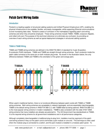
4I E T W I R I N G R E G U L AT I O N S B S 7 6 7 1 1 8 T H E D I T I O N—The IET Wiring Regulations requireall new electrical system designsand installations, as well asalterations and additions to existinginstallations, to be assessed againsttransient overvoltage risk and,where necessary, protected usingappropriate surge protectionmeasures (in the form ofSurge Protection Devices SPDs).
T R A N S I E N T O V E R V O LTA G E P R OT E C T I O N - I N T R O D U C T I O N3—Transient overvoltage protectionIntroductionBased on the IEC 60364 series, the 18th Edition ofBS 7671 Wiring regulations covers the electrical installationof buildings including the use of surge protection.The 18th Edition of BS 7671 applies to the design,erection and verification of electrical installations,and also to additions and alterations to existinginstallations. Existing installations that havebeen installed in accordance with earlier editionsof BS 7671 may not comply with the 18th editionin every respect. This does not necessarilymean that they are unsafe for continued use orrequire upgrading.A key update in the 18th Edition relates toSections 443 and 534, which concern protection ofelectrical and electronic systems against transientovervoltages, either as a result of atmosphericorigin (lightning) or electrical switching events.Essentially, the 18th Edition requires all newelectrical system designs and installations,as well as alterations and additions to existinginstallations, to be assessed against transientovervoltage risk and, where necessary, protectedusing appropriate protection measures(in the form of SPDs).Within BS 7671: Section 443 defines the criteria for riskassessment against transient overvoltages,considering the supply to the structure,risk factors and rated impulse voltagesof equipment Section 534 details the selection and installationof SPDs for effective transient overvoltageprotection, including SPD Type, performanceand co-ordinationReaders of this guide should be mindful of theneed to protect all incoming metallic servicelines against the risk of transient overvoltages.BS 7671 provides focussed guidance for theassessment and protection of electricaland electronic equipment intended to beinstalled on AC mains power supplies.In order to observe the Ligntning Protection Zone LPZconcept within BS 7671 and BS EN 62305, all otherincoming metallic service lines, such as data, signaland telecommunications lines, are also a potentialroute through which transient overvoltages todamage equipment. As such all such lines will requireappropriate SPDs.BS 7671 clearly points the reader back to BS EN 62305and BS EN 61643 for specific guidance. This iscovered extensively in the Furse guide to BS EN 62305Protection Against ANT:Equipment is ONLYprotected againsttransient overvoltages ifall incoming / outgoingmains and data lineshave protection fitted.
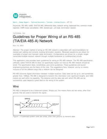
I E T W I R I N G R E G U L AT I O N S B S 7 6 7 1 1 8 T H E D I T I O N4—Transient overvoltage protectionSafeguarding your electrical systemsDAMAGE 1.5 inalsystem voltage(e.g. 230 V)Safe Operating AreaDegradation 2x peakoperating voltage(e.g. 715 V L-N)DegradationDAMAGE—01—Why is transient overvoltageprotection so important?Transient overvoltages are short duration surgesin voltage between two or more conductors(L-PE, L-N or N-PE), which can reach up to 6 kV on230 Vac power lines, and generally result from: Atmospheric origin (lightning activitythrough resistive or inductive coupling(see Figures 02 & 03), and/or Electrical switching of inductive loadsTransient overvoltages significantly damageand degrade electronic systems. Outright damageto sensitive electronic systems, such as—01 Equipment risk –Degradation of electronicsystems begins at lowertransient overvoltagelevels and affects criticalelectronic systemswhenever the impulseimmunity of the equipmentis compromised.—02 Resistive coupling –Resistively coupledtransients are causedby differences inpotential between twoconnected earths.—03 Inductive coupling –Inductively coupledtransients are causedby electromagneticpick-up.—02computers etc, occurs when transientovervoltages between L-PE or N-PE exceed thewithstand voltage of the electrical equipment(i.e. above 1.5 kV for Category I equipmentto BS 7671 Table 443.2).Equipment damage leads to unexpected failures andexpensive downtime, or risk of fire/electric shockdue to flashover, if insulation breaks down.Degradation of electronic systems, however, beginsat much lower overvoltage levels and can causedata losses, intermittent outages and shorterequipment lifetimes (see Figure 01).Where continuous operation of electronic systemsis critical, for example in hospitals, banking andmost public services, degradation must beavoided by ensuring these transient overvoltages,which occur between L-N, are limited belowthe impulse immunity of equipment. This can becalculated as twice the peak operating voltageof the electrical system, if unknown(i.e. approximately 715 V for 230 V systems).Protection against transient overvoltages can beachieved through installation of a coordinatedset of SPDs at appropriate points in the electricalsystem, in line with BS 7671 Section 534 and theguidance provided in this publication.Selecting SPDs with lower (i.e. better) voltageprotection levels (U P) is a critical factor,especially where continuous usage of electronicequipment is essential.—03
T R A N S I E N T O V E R V O LTA G E P R OT E C T I O N - S A F E G U A R D I N G YO U R E L E C T R I C A L S Y S T E M S5—Table 1 – Examples of overvoltage protection requirments to BS 7671Consequence caused by overvoltage ExamplesTypical facilitiesOvervoltage protection required?Serious injury to orloss of human lifeLoss of safety services,medical care facilitiesHospitals, care homes,home dialysis equipmentYesInterruption of public servicesand/or damage to cultural heritageLoss of utility and IT services,damage to historic buildingsPower stations, data centres,heritage status buildings likemuseums, castlesYesInterruption of commercial orindustrial activityLoss of electronic systemswithin service sectors,manufacturing processesBanks, hotels, supermarkets,industrial plants, farmsYesInterruption to an installationwith a large number of co-locatedindividualsLoss of safety systems for fire/security and access control,IT systemsOffices, universities, schools,residential tower blocksYesConsequences caused byovervoltage for a single dwellingunit where an assessment showsthe total value of electricalinstallation and connectedequipment does not necessitatethe cost of SPD protection (443.4)Loss of household electronics doesnot warrant cost of overvoltageprotectionResidential homesNoInterruption to all other casesthan detailed aboveLoss of systems to small businessHome based office,convenience storePerform risk assessmentof 443.5 to determineCalculated Risk Level CRLNo if CRL 1000Yes if CRL 1000Yes if no risk assessmentis performed—Risk assessmentAs far as Section 443 is concerned, the fullBS EN 62305-2 risk assessment method must beused for high risk installations such as nuclearor chemical sites where the consequences oftransient overvoltages could lead to explosions,harmful chemical or radioactive emissionsthus affecting the environment.If the CRL value is less than 1000 (or less than a 1in 1000 chance) then SPD protection shall beinstalled. Similarly if the CRL value is 1000 or higher(or greater than a 1 in 1000 chance) then SPDprotection is not required for the installation.Outside of such high risk installations, if there is arisk of a direct lightning strike to the structureitself or to overhead lines to the structure SPDs willbe required in accordance with BS EN 62305.CRL fenv / (LP x Ng)Section 443 takes a direct approach for protectionagainst transient overvoltages which is determinedbased on the consequence caused by overvoltageas per Table 1 above.Calculated Risk Level CRL – BS 7671BS 7671 clause 443.5 adopts a simplified version ofrisk assessment derived from the complete andcomplex risk assessment of BS EN 62305-2.A simple formula is used to determine a CalculatedRisk Level CRL.The CRL is best seen as a probability or chanceof an installation being affected by transientovervoltages and is therefore used to determine ifSPD protection is required.The CRL is found by the following formula:Where: fenv is an environmental factor and the value offenv shall be selected according to Table 443.1 L P is the risk assessment length in km N g is the lightning ground flash density (flashesper km² per year) relevant to the location ofthe power line and connected structure(see Lightning flash Density Ng map of UK inFigure 05)The fenv value is based on the structure'senvironment or location. In rural or suburbanenvironments, structures are more isolated andtherefore more exposed to overvoltages ofatmospheric origin compared to structures inbuilt up urban locations.
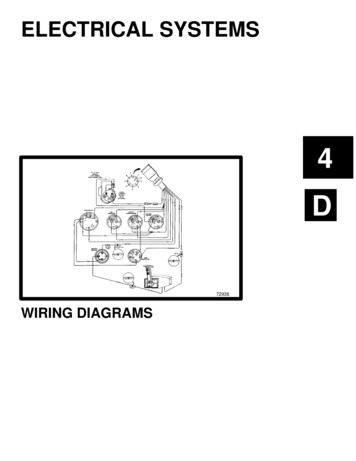
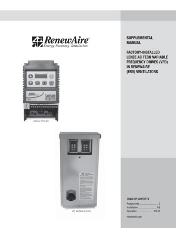
I E T W I R I N G R E G U L AT I O N S B S 7 6 7 1 1 8 T H E D I T I O N6—Table 2 – Determination of fenv value based on environement (Table 443.1 BS 7671)EnvironmentDefinitionExamplefenv valueRuralArea with a low density ofbuildingsCountryside85SuburbanArea with a medium density ofbuildingsTown outskirts85UrbanArea with a high density ofbuildings or densely populatedcommunities with tall buildingsTown centre850—04 Lengths to considerfor the calculation of Lp(Figure 443.3 BS 7671)overvoltage protective device installed in the HVpower network (see Figure 04) to the origin ofthe electrical installation, whichever is the smaller.If the distribution network's lengths are totallyor partially unknown then L PAL shall be takenas equal to the remaining distance to reach a totallength of 1 km. For example, if only the distanceof underground cable is known (e.g. 100 m),the most onerous factor L PAL shall be taken asequal to 900 m. An illustration of an installationshowing the lengths to consider is shownin Figure 04 (Figure 443.3 of BS 7671).Risk assessment length LPThe risk assessment length LP is calculatedas follows:LP 2 LPAL LPCL 0.4 LPAH 0.2 LPCH (km)Where: L PAL is the length (km) of low-voltageoverhead line L PCL is the length (km) of low-voltage underground cable L PAH is the length (km) of high-voltageoverhead line L PCH is the length (km) of high-voltage underground cableThe total length (L PAL L PCL L PAH L PCH) islimited to 1 km, or by the distance from the firstGround flash density value N gThe ground flash density value N g can be takenfrom the UK lightning flash density mapin Figure 05 (Figure 443.1 of BS 7671) – simplydetermine where the location of the structure isand choose the value of N g using the key.For example, central Nottingham has an N g valueof 1. Together with the environmental factor fenv,the risk assessment length L P, the N g value canbe used to complete the formula data forcalculation of the CRL value and determine ifovervoltage protection is required or not.The UK lightning flash density map (Figure 05) anda summary flowchart (Figure 06) to aid thedecision making process for the application ofSection 443 (with guidance to the Types ofSPD guide to Section 534) follows. Some riskcalculation examples are also provided.—04LPALLPAH1LPCH23LPCL—Key1) Surge arrestor (overvoltage protective device) on the overhead HV system2) HV/LV transformer3) Origin of the electrical installationLPCL
UK FL A SH DENSIT Y MAP—Regions:1 City of Edinburgh2 City of Glasgow3 Clackmannanshire4 East Ayrshire5 East Dunbartonshire6 East Lothian7 East Renfrewshire8 Falkirk9 Inverclyde10 Midlothian11 North Ayrshire12 North Lanarkshire13 Renfrewshire14 South Ayrshire15 South Lanarkshire16 West Dunbartonshire17 West Lothian18 Conwy19 Denbighshire20 Flintshire21 Gwynedd22 Wrexham23 Bristol24 Blaenau Gwent25 Bridgend26 Caerphilly27 Cardiff28 Merthyr Tydfil29 Monmouthshire30 Neath & Port Talbot31 Newport32 Rhondda Cynon Taff33 Swansea34 Torfaen35 Vale of Glamorgan7— Copyright 2018 ABB. All rights reserved.Specifications subject to change without notice.HighlandMorayAberdeenshireAngusPerth & KinrossArgyll & ButeFifeStirling3118516913 276117121015Scottish Borders414DerryNorthumberlandDumfries & GallowayAntrimDonegalTyne & WearTyroneDurhamFermanaghCumbriaDownArmaghNorth YorkshireIsle of ManEast Ridingof YorkshireLancashireWest YorkshireGt ManchesterSouth hropshireRutlandNorfolkWest 3529Oxfordshire3127HertfordshireEssex3432 eWest SussexDorsetDevonCornwall—05 UK lightningflash density map(Figure 443.1 BS 7671)Isle of WightEast Sussex
I E T W I R I N G R E G U L AT I O N S B S 7 6 7 1 1 8 T H E D I T I O N8—06STARTDirect or nearbylightning strokes onthe structure; or structureswith risk of explosion; or wherethe damage may also involve theenvironment (e.g. chemicalor radioactive) (443.1.1)YESProtection against overvoltages required– selected and installed to Section 534Where the structure is equipped withan external lightning protection system LPSor protection against the effects of directlightning on overhead lines Type 1 SPDs shallbe installed as close as possible to the originof the electrical installation (534.4.1.3).NOConsequencescaused byovervoltage leads to:a) Serious injury to or lossof human lifeb) Interruption of public services and/or damage to cultural heritagec) Interruption of commercialor industrial activityd) Interruption to an installationwith a large number ofco-located individuals(443.4)Refer to BS EN 62305-2 for riskmanagement to determinespecific protection againstovervoltage requirements(443.1.1, Note 8)YESWhere the structure is not equipped with anexternal LPS or does not require protectionagainst the effects of direct lightning,Type 2 SPDs shall be installed as close aspossible to the origin of the electricalinstallation (534.4.1.4).SPDs installed close to sensitive equipmentto further protect against switchingtransients originating within the buildingshall be Type 2 or Type 3 (534.4.1.1).(Note SPDs can be combined Type SPDse.g. T1 2, T1 2 3, T2 3–see Appendix 16).NOConsequencescaused by overvoltagefor a single dwelling unit wherean assessment shows the totalvalue of electrical installation andconnected equipment doesnot necessitate the cost ofSPD protection (443.4)YESProtection againstovervoltagesnot required ifequipment complieswith required ratedimpulse voltage(Table 443.2)YESYESNOConsequencescaused by overvoltageleads to interruptiontoall other installationsthan detailedabove (443.4)YESPerform riskassessmentto determineCalculatedRisk Level(CRL) value(443.5)CRL valueis 1000Check if data, signaland telecom linesrequire protectionto preserve LightningProtection ZonesLPZ concept (443.1.1,534.1, 534.4.1.2,534.4.1.6)CRL 1000or if no riskassessment isperformedEND
E X A M P L E S O F C A LC U L AT E D R I S K L E V E L C R L F O R T H E U S E O F S P D S—06 Risk assementSPD decision flow chartfor installations withinthe scope of thisBS 7671 18th Edition.9Examples of calculated risk level CRL for the useof SPDs (BS 7671 informative Annex A443).In this case, SPD protection is not a requirementas CRL value is greater than 1000.Example 1 - Building in rural environment inNotts with power supplied by overhead linesof which 0.4 km is LV line and 0.6 km is HV lineGround flash density N g for central Notts 1(from Figure 05 UK flash density map).Example 3 - Building in urban environment locatedin southern Shropshire – supply details unknownGround flash density N g for southern Shropshire 0.5 (from Figure 05 UK flash density map).Environmental factor fenv 85 (for ruralenvironment – see Table 2)Risk assessment length L PLP 2 LPAL LPCL 0.4 LPAH 0.2 LPCHEnvironmental factor fenv 850(for urban environment – see Table 2)Risk assessment length LPLP 2 LPAL LPCL 0.4 LPAH 0.2 LPCHLP (2 x 1)LP (2 0.4) (0.4 0.6)LP 2LP 1.04Where: LPAL is the length (km) of low-voltage overhead line 1(details of supply feed unknown – maximum 1 km) LPAH is the length (km) of high-voltage overhead line 0 L PCL is the length (km) of low-voltageunderground cable 0 L PCH is the length (km) of high-voltageunderground cable 0Where: LPAL is the length (km) of low-voltage overhead line 0.4 LPAH is the length (km) of high-voltage overhead line 0.6 L PCL is the length (km) of low-voltageunderground cable 0 L PCH is the length (km) of high-voltageunderground cable 0Calculated Risk Level (CRL)CRL fenv / (LP Ng)CRL 85 / (1.04 1)CRL 81.7In this case, SPD protection shall be installed asthe CRL value is less than 1000.Calculated Risk Level CRLCRL fenv / (LP Ng)CRL 850 / (2 0.5)CRL 850In this case, SPD protection shall be installed asthe CRL value is less than 1000.Example 4 - Building in urban environment locatedin London supplied by LV underground cableGround flash density N g for London 0.8(from Figure 05 UK flash density map)Example 2 - Building in suburban environment locatedin north Cumbria supplied by HV underground cableGround flash density Ng for north Cumbria 0.1(from Figure 05 UK flash density map)Environmental factor fenv 85 (for suburbanenvironment – see Table 2)Environmental factor fenv 850(for urban environment – see Table 2)Risk assessment length L PRisk assessment length LPLP 2 LPAL LPCL 0.4 LPAH 0.2 LPCHLP 0.2 x 1LP 0.2Where: LPAL is the length (km) of low-voltage overhead line 0 LPAH is the length (km) of high-voltage overhead line 0 L PCL is the length (km) of low-voltageunderground cable 0 L PCH is the length (km) of high-voltageunderground cable 1Calculated Risk Level (CRL)CRL fenv / (LP Ng)CRL 85 / (0.2 0.1)CRL 4250LP 2 LPAL LPCL 0.4 LPAH 0.2 LPCHLP 1Where: LPAL is the length (km) of low-voltage overhead line 0 LPAH is the length (km) of high-voltage overhead line 0 L PCL is the length (km) of low-voltageunderground cable 1 L PCH is the length (km) of high-voltageunderground cable 0Calculated Risk Level (CRL)CRL fenv / (LP Ng)CRL 850 / (1 0.8)CRL 1062.5In this case, SPD protection is not a requirementas the CRL value is greater than 1000.
10I E T W I R I N G R E G U L AT I O N S B S 7 6 7 1 1 8 T H E D I T I O N—Transient overvoltage protectionSelection of SPDs to BS 7671Selection of SPDs to BS 7671The scope of Section 534 of BS 7671 is to achieveovervoltage limitation within AC power systems toobtain insulation co-ordination, in line with Section443, and other standards, including BS EN 62305-4.Overvoltage limitiation is achieved throughinstallation of SPDs as per the recommendationsin Section 534 (for AC power systems), andBS EN 62305-4 (for other power and data, signalor telecommunications lines).Selection of SPDs should achieve the limitationof transient overvoltages of atmospheric origin,and protection against transient overvoltagescaused by direct lightning strikes orlightning strikes in the vicinity of a buildingprotected by a structural Lightning ProtectionSystem LPS.SPD selectionSPDs should be selected according to thefollowing requirements: Voltage protection level (U P) Continuous operating voltage (U C) Temporary overvoltages (UTOV) Nominal discharge current (I nspd) andimpulse current (I imp) Prospective fault current and the follow currentinterrupt ratingThe most important aspect in SPD selection is itsvoltage protection level (U P). The SPD’s voltageprotection level (U P) must be lower than the ratedimpulse voltage (U W) of protected electricalequipment (defined within Table 443.2), or forcontinuous operation of critical equipment,its impulse immunity.Where unknown, impulse immunity can be calculatedas twice the peak operating voltage of theelectrical system (i.e. approximately 715 V for230 V systems). Non-critical equipment connectedto a 230/400 V fixed electrical installation(e.g. a UPS system) would require protection by anSPD with a U P lower than Category II rated impulsevoltage (2.5 kV). Sensitive equipment, such aslaptops and PCs, would require additional SPDprotection to Category I rated impulse voltage (1.5 kV).These figures should be considered as achievinga minimal level of protection. SPDs with lowervoltage protection levels (U P) offer much betterprotection, by: Reducing risk from additive inductive voltageson the SPD’s connecting leads Reducing risk from voltage oscillationsdownstream which could reach up to twice theSPD’s U P at the equipment terminals Keeping equipment stress to a minimum, aswell as improving operating lifetimeIn essence, an enhanced SPD (SPD* to BS EN 62305)would best meet the selection criteria, as suchSPDs offer voltage protection levels (U P)considerably lower than equipment's damagethresholds and thereby are more effective inachieving a protective state.As per BS EN 62305, all SPDs installed to meet therequirements of BS 7671 shall conform to theproduct and testing standards (BS EN 61643 series).
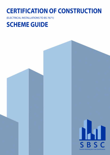
11Service entrance/Main distribution boardL1OCPDSub-distribution boardTerminal equipmentLinelength 10 mL1L2L2L3L3NNPENLinelength 10 mPEOCPDOCPDRisk ofswitchingtransientL1L2L3If RED replaceNLL'L2L2'L3L3'NN'250 AgLPATENTAPPLIEDFORESP 415/I/TNSEnhanced Mains ProtectorEN/IEC 61643EnhancedMainsProtectorlimp 25kA/modelmax 100kA/modeln 25kA/modeUc 320VACUp 1.4kVUres(limp) 1.3kVPE141112STATUSESP 415/I/TNSType 1 2 SPDESP 415 D1/LCD Full ModeType 1 2 3 SPDCritical equipment(e.g. hospitalequipment)Fixed equipment(e.g. UPS)Main earthing terminalESP 415/I/TNS with Type 1performance installed atservice entrance to diverthigh energy lightningcurrents to earth, andremove risk of flashover.OCPD: Overcurrent protective device(eg. fuse MCB)ESP 415 D1/LCD with Type 2performance installed at subdistribution protects fixedequipment on the electricalinstallation against transientovervoltages.Combined Type 2 3performance of the SPDinstalled at sub-distributionprotects downstreamsensitive equipment againsttransient overvoltages.Plug-in ESP MC with Type 3performance protects criticalequipment at local levelagainst switching transients.—07—07 Typical installation ona 230/400 V TN-C-S/TN-Ssystem, using FurseSPDs, to meet therequirements of BS 7671.Compared to standard SPDs, enhanced SPDs offerboth technical and economic advantages: Combined equipotential bonding and transientovervoltage protection (Type 1 2 & Type 1 2 3) Full mode (common and differential mode)protection, essential to safeguard sensitiveelectronic equipment from all types of transientovervoltage - lightning & switching and Effective SPD co-ordination within a single unitversus installation of multiple standard TypeSPDs to protect terminal equipmentFigure 07 demonstrates how effectiveprotection comprises a service entrance SPD todivert high energy lightning currents to earth,followed by coordinated downstream SPDsat appropriate points to protect sensitive andcritical equipment.—Compliance toBS EN 62305/BS 7671Where a building includes a structural LPS, orconnected overhead metallic services at risk froma direct lightning strike, equipotential bondingSPDs (Type 1 or Combined Type 1 2) mustbe installed at the service entrance, to removerisk of flashover.BS 7671 Section 534 focuses guidance onselection and installation of SPDs to limittransient overvoltages on the AC power supply.BS 7671 Section 443 states that‚ transientovervoltages transmitted by the supply distributionsystem are not significantly attenuated downstreamin most installations BS 7671 Section 534therefore recommends that SPDs are installedat key locations in the electrical system: As close as practicable to the origin of theinstallation (usually in the main distributionboard after the meter) As close as practicable to sensitiveequipment (sub-distribution level), and localto critical equipmentFigure 07 shows a typical installation on a230/400 V TN-CS/TN-S system using Furse SPDs,to meet the requirements of BS 7671.Selecting appropriate SPDsSPDs are classified by Type within BS 7671 followingthe criteria established in BS EN 62305.Installation of Type 1 SPDs alone however doesnot provide protection to electronic systems.Transient overvoltage SPDs (Type 2 and Type 3, orCombined Type 1 2 3 and Type 2 3) shouldtherefore be installed downstream of the serviceentrance.These SPDs further protect againstthose transient overvoltages caused by indirectlightning (via resistive or inductive coupling)and electrical switching of inductive loads.Combined Type SPDs (such as the Furse ESPD1 Series and ESP M1/M2/M4 Series) significantlysimplify the SPD selection process, whetherinstalling at the service entrance or downstreamin the electrical system.
I E T W I R I N G R E G U L AT I O N S B S 7 6 7 1 1 8 T H E D I T I O N12—ABB Furse ESP range of SPDsEnhanced solutions to BS EN 62305/BS 7671The Furse ESP range of SPDs (power, data andtelecom) are widely specified in all applications toensure the continuous operation of criticalelectronic systems. They form part of a completelightning protection solution to BS EN 62305.Furse ESP M and ESP D power SPD products areType 1 2 3 devices, making them suitable forinstallation at the service entrance, whilst givingsuperior voltage protection levels (enhanced toBS EN 62305) between all conductors or modes.The active status indication informs the user of: Loss of power— Loss of phaseThe SPD and supplystatus can also be Excessive N-E voltagemonitored remotely via Reduced protectionthe volt-free contact.—Protection for 230/400 V TN-S or TN-C-S suppliesSupply typeExample 1Example 2Example 3Example 4No external lightningprotection system fittedNo external lightningprotection system fittedExternal lightningprotection system fittedExternal lightningprotection system fittedUnderground mainssupply feedExposed overhead mainssupply feedMultiple connectedmetallic servicesNo. of services lGroundlevelPowerPowerDataTelecomWaterGasPowerType 1 2 3Type 1 2 OR Type 1 2 3UnknownMain distribution board (MDB) Type 1 2 3Type 1 2 OR Type 1 2 33 Phase 400 VService entrance, afterelectricity meter (Maindistribution board (MDB)).Type 1 2 3 SPDs suchas the ESP M and D seriesare used where the MDBdirectly feeds criticalelectronicsESP 415/III/TNS OR ESP 415 M2 ESP 415 D1 OR ESP 415 M1Series for SeriesSeriescriticalelectronicsSub-distribution board (SDB)Located 10 m fromMDB feeding electronicequipmentFinal circuit equipmentLocated 10 m from SDB—Protection for datasignal and telecomsapplicationsESP 415 D1 OR ESP 415 M1SeriesSeriesGroundlevelFor LPL I & II: OR ESP 415 M4ESP 415/I/TNSSeries forLPL III or IV:criticalESP 415/III/TNS electronicsType 1 2 3For 3 Phase 400 VESP 415 D1 Series, orESP 415 M1 SeriesORFor 13 A sockets (e.g. servers)ESP MCESP MC/TN/RJ11ESP MC/Cat-5eFused spursESP 240D-10AESP 240D-32AORFor 1 Phase 230 VESP 240 D1 Series, orESP 240 M1 SeriesConsumer unitsFurse MMP 2C275/1 1T
A B B O V R P O W E R S P D S - C O S T E F F E C T I V E P R OT E C T I O N TO B S 7 6 7 113—ABB OVR power SPDsCost effective protection to BS 7671The ABB OVR range of SPDs compliment ABB'sDIN rail product solutions offering cost effectiveprotection for commercial, industrial anddomestic installations.Safety reserve system Two protection components in parallel inside acartridge guarantee best possible protection When one component is damged, the mechanicalindicator will switch to half green / half red,triggering the volt-free contact At this stage the product should be replaced,but the user still has protection during theordering and installation process When both components are damaged, the endof life indicator will become completely red—Main section boardPart No. / Order codeDescriptionOVR T1-T2 3N 12.5-275sP TS QS / 2CTB815710R0700TNS/TT 230/400V3Ph N networksType 1 2 ABB surge protectivedevices have a high impulsecurrent (10/350 waveform)withstand capacity whilstensuring a low (better) voltageprotection level (Up)CharacteristicsALARMRES ONFeaturesMulti-mode protectionEnd of life SPD visual indicator with safety reserveDIN rail mounting for quick installationCompact designAuxillary contact TS for remote status indicationQuicksafe disconnection at end of lifel 1643-11EN 61643-11TSAUXILIARYCONTACT—Sub-distribution boardPart No. / Order codeDescriptionOVR T2 3N 40-275sP TS QS / 2CTB815704R0800TNS/TT 230/400V3Ph N networksType 2 ABB surgeprotective devices aredesigned to protect electricalinstallations and sensitiveequipment against indirectsurge currentsCharacteristicsFeaturesMulti-mode protectionEnd of life SPD visual indicator with safety reservePlug-in cartridgeDIN rail mounting for quick installationAuxillary contact TS for remote status indicationQuicksafe disconnection at end of lifeALARMl maxPlug-inRES ON40kAMODULEIEC61643-11EN 61643-11TSAUXILIARYCONTACT—Consumer unitPart No. / Order codeOVR T2 1N 40-275sP TS QS / 2CTB815704R0200TNS/TT 230V1Ph N networksDescriptionFeaturesType 2 ABB surgeprotective devices aredesigned to protect electricalinstallations and sensitiveequipment against indirectsurge currentsMulti-mode protectionCharacteristicsEnd of life SPD visual indicator with safety reservePlug-in cartridgeDIN rail mounting for quick installationAuxillary contact TS for remote status indicationQuicksafe disconnection at end of lifeALARMl maxPlug-inRES ON20kAMODULEIEC61643-11EN 61643-11TSAUXILIARYCONTACT
14I E T W I R I N G R E G U L AT I O N S B S 7 6 7 1 1 8 T H E D I T I O N—Installation of SPDsSection 534, BS 7671—Table 3 – Compati
of the electrical system, if unknown (i.e. approximately 715 V for 230 V systems). Protection against transient overvoltages can be achieved through installation of a coordinated . set of SPDs at appropriate points in the electrical system, in line with BS 7671 Sec