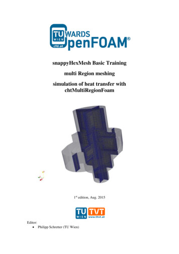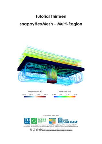
Transcription
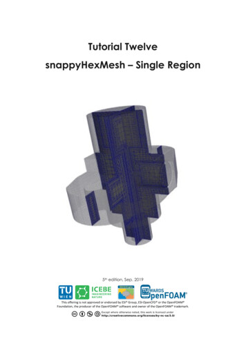
Tutorial TwelvesnappyHexMesh – Single Region4th edition, Jan. 2018This offering is not approved or endorsed by ESI Group, ESI-OpenCFD or the OpenFOAM Foundation, the producer of the OpenFOAM software and owner of the OpenFOAM trademark.
OpenFOAM Basic TrainingTutorial TwelveEditorial board: Bahram Haddadi Christian Jordan Michael HarasekContributors: Philipp Schretter Yitong ChenCompatibility: OpenFOAM 5.0 OpenFOAM v1712Cover picture from: Philipp SchretterAttribution-NonCommercial-ShareAlike 3.0 Unported (CC BY-NC-SA 3.0)This is a human-readable summary of the Legal Code (the full license).DisclaimerYou are free:- to Share — to copy, distribute and transmit the work- to Remix — to adapt the workUnder the following conditions:- Attribution — You must attribute the work in the manner specified by the author orlicensor (but not in any way that suggests that they endorse you or your use of the work).- Noncommercial — You may not use this work for commercial purposes.- Share Alike — If you alter, transform, or build upon this work, you may distribute theresulting work only under the same or similar license to this one.With the understanding that:- Waiver — Any of the above conditions can be waived if you get permission from thecopyright holder.- Public Domain — Where the work or any of its elements is in the public domain underapplicable law, that status is in no way affected by the license.- Other Rights — In no way are any of the following rights affected by the license:- Your fair dealing or fair use rights, or other applicable copyright exceptions andlimitations;- The author's moral rights;- Rights other persons may have either in the work itself or in how the work is used, suchas publicity or privacy rights.- Notice — For any reuse or distribution, you must make clear to others the license termsof this work. The best way to do this is with a link to this web page.For more tutorials visit: www.cfd.at
OpenFOAM Basic TrainingTutorial TwelveBackgroundIn this tutorial, we will familiarize ourselves with the snappyHexMesh tool in OpenFOAM . Thisutility generates 3D meshes containing hexahedra and split-hexahedra. We will also introducedifferent types of meshes with complex geometries and compare the snappyHexMesh tool withother mesh generation tools.1. Meshes with complex geometriesSo far we have only worked with meshes in Cartesian co-ordinates, however, many engineeringproblems involve complex geometries that do not fit exactly in Cartesian co-ordinates. In suchcases, it would be much more advantageous to work with grids that can handle curvature andgeometric complexity more naturally.CFD methods for complex geometries are classified into two groups:1) structured curvilinear grid arrangements2) unstructured grid arrangementsIn a structured grid arrangements: Cells center points are placed at the intersections of co-ordinates lines Cells have a fixed number of neighboring cells Cells center points can be mapped into a matrix based on their location in the grid Structure and position in the matrix is given by indices (I, J in two dimensions and I, J, K inthree dimensions)For the most complex geometries it may be necessary to sub-divide the flow domain into severaldifferent blocks, where each mesh cell is a block, this is known as block-structured grids. Thenext level of complexity is the unstructured grids. It gives unlimited geometric flexibility, here thelimitations of structured grids do not apply – but at the cost of higher programming andcomputational efforts. Unstructured grids also allow the most efficient use of computing resourcesfor complex flows, so this technique is now widely used in industrial CFD.2. Mesh generation toolsThere are a number of advanced meshing tools available, both commercial and free source. Themajor mesh generators are ANSYS GAMBIT , ICEM, Salome, snappyHexMesh and cfMesh. Herewe will learn about GAMBIT , snappyHexMesh and cfMesh tools in detail.2.1. GAMBIT GAMBIT is a 3D unstructured tool, to specify the meshing scheme in it, two parameters must bespecified: Elements Type
OpenFOAM Basic TrainingTutorial TwelveThe Elements parameter defines the shape(s) of the elements that are used to mesh the object. TheType parameter defines the pattern of mesh elements on the object. It has a single graphical userinterface which brings geometry creation and meshing together in one environment.2.2. snappyHexMeshIn contrast to GAMBIT , which incorporates both mesh generation and refinement, thesnappyHexMesh tool built within OpenFOAM requires an existing geometry base mesh to workwith. The base mesh usually comes from the blockMesh tool. This utility has the following keyfeatures: allow parallel execution to speed up the processsupports geometry data from STL/OBJ filesaddition of internal and wall layerszonal meshingThe key steps involved when running snappyHexMesh are: Castellation: The cells which are beyond a region set by a predefined point are deletedSnapping: Reconstructs the cells to move the edges from inside the region to the requiredboundaryLayering: Creates additional layers in the boundary region.The advantages of snappyHexMesh over the other mesh generation tools are as follows: No commercial software package is ultimately necessary. For the meshing, the OpenFOAM environment is sufficient and no further software is necessary.The geometry can be created with any CAD program like CATIA , FreeCAD, etc. As thegeometry is to be only surface data, the files need to be in .stl, .nas or .obj. format.The meshing process can be run in parallel mode. If high computational capabilities areavailable, high quality meshes can be generated in little time.2.3. cfMeshcfMesh is an open-source library for mesh generation implemented within the OpenFOAM framework (similar to snappyHexMesh). Currently cfMesh is capable of producing mesh ofCartesian type in both 2D and 3D, tetrahedral and polyhedral types.The fundamental work-flow of the tool starts from a mesh template, then followed by a meshmodifier. The modifier allows for efficient parallelization using shared memory parallelization(SMP) and distributed memory parallelization using MPI.
OpenFOAM Basic TrainingTutorial TwelvesnappyHexMesh – flangeSimulationThe procedure described in this tutorial is structured in the following order: Creation of the geometry data Meshing a geometry with one single region Run an OpenFOAM simulation with the generated mesh using scalarTransportFoamObjectives The aim of the tutorial is to give a basic introduction to single region meshing with the meshingtool snappyHexMesh Understanding the advantages of snappyHexMesh Understanding the three basic steps of snappyHexMeshData processingImport your simulation to ParaView. Analyze the heat distribution in the flange.
OpenFOAM Basic TrainingTutorial Twelve1. Pre-processing1.1. Copy tutorialCopy the following tutorial to your working directory. FOAM TUTORIALS/mesh/snappyHexMesh/flange1.2. Set-up of stl filesNormally the .stl files are created using CAD software, such as CATIA and freeCAD. stl filescontain information about the solid geometry. However, in this tutorial the stl files are available tobe copied from the OpenFOAM tutorials folder. To do this, copy the stl files from the belowlocation to the constant/triSurface of your running case directory. FOAM TUTORIALS/resources/geometry/flange.stl.gz1.3. constant directoryThe constant directory must initially have the following folder:-triSurface:The folder triSurface should contain a file with the geometry data to be meshed (stl, nas, obj).The file name is to be used as a reference pointer in later stages.Note: The stl file should be in ascii format. All the stl files (different boundaries stl files) shouldform a closed geometry together.1.4. system directoryFor creating a mesh using snappyHexMesh the following files should be present in systemdirectory:- blockMeshDictFor meshing using snappyHexMesh a background mesh is needed, which should surround thegeometry surface (e.g. stl file) file. The background mesh will be refined based on the settings inthe snappyHexMeshDict and the extra parts will be removed. Usually the background mesh iscrated using blockMesh. Here we define a base mesh.Note: To ensure that the sharp edges are refined properly, it is very important to create perfectcube cells in the background mesh using blockMesh utility.-decomposeParDictThe meshing using snappyHexMesh can be also performed in parallel mode. If the mesh is to berun in parallel using the decomposePar utility, this file defines the parameters for distributedprocessors-meshQualityDictParameters to be checked for mesh quality and their values are defined in this file.
OpenFOAM Basic TrainingTutorial Twelve-surfaceFeatureExtractDict:Using surfaceFeatureExtract utility prior to meshing with snappyHexMesh helps to extract thesharp edges and have a better mesh with snappyHexMesh on these edges. All edges are marked,whose adjacent surfaces normal are at an angle less than the angle specified inincludedAngle. For the included angels, a special level of refinement can be set in thefeatures sub-dictionary in the snappyHexMeshDict.//* * * * * * * ** * * * * * * * * * * * * * * * * * * * * * * * * * * * * * * * * * * /-yes;}* * * * * * * ** * * * * * * * * * * * * * * * * * * * * * * * * * * * * * * * * * * //snappyHexMeshDict:This file includes the settings for running the snappyHexMesh. As mentioned in the Backgroundsection meshing using this tool has three steps:1 – Castellating2 – Snapping3 – LayeringIn the first section of this file you can set castellatedMesh, snap, addLayers to true orfalse depending on the stages required.////* * * * * * * ** * * * * * *castellatedMeshsnapaddLayers* * * * * * * ** * * * * * ** * * * * * * * * * * * * * * * * * * * * * * * * * * * //true;true;true;* * * * * * * * * * * * * * * * * * * * * * * * * * * * //The Geometry sub-dictionary lists all surfaces used by snappyHexMeshDict, except theblockMesh geometry, and defines a name for each of them to be used as a reference.Then we specify a region of the domain that we want to refine. The refined region is given anarbitrary name; in this case, it is refineHole which is a sphere with its center and radiusdefined.//* * * * * * * ** * * * * * * * * * * * * * * * * * * * * * * * * * * * * * * * * * * //geometry{flange{type triSurfaceMesh;file “flange.stl”;}refineHole{type searchableSphere;centre (0 0 -0.012);radius 0.003;}};// * * * * * * * ** * * * * * * * * * * * * * * * * * * * * * * * * * * * * * * * * * * //
OpenFOAM Basic TrainingTutorial TwelveOpenFOAM v1712: The geometry section of the snappyHexMeshDict looks as following://* * * * * * * ** * * * * * * * * * * * * * * * * * * * * * * * * * * * * * * * * * * //geometry{flange.stl{type triSurfaceMesh;name flange;} };// * * * * * * * ** * * * * * * * * * * * * * * * * * * * * * * * * * * * * * * * * * * //CASTELLATINGThe castellatedMeshControls sub-dictionary is used for user-defined edge refinement. Ituses the eMesh files, created with the surfaceFeatureExtract command. These eMesh files areextracted parts from the stl surfaces, specified in the surfaceFeatureExtractDict.features allows explicit feature edge refinement and a level is chosen for any cell intersectedby its edges.refinementSurfaces are for surface based refinement. Every surface is specified with twolevels. The first level is the minimum level that every cell intersecting the surface gets refinedup to. The second level is the maximum level of refinement.resolveFeatureAngle is an important setting. Edges, whose adjacent surfaces normal are atan angle higher than the value set, are resolved. The lower the value, the better the resolution atsharp edges.refinementRegions: The refinement level of the previous specified refinementHole isdefined. The cells in this region are split up to the number of cells defined, or until the maxnumber of cells is reached.locationInMesh: Important coordinate for single region cases, to define a region which is tobe kept from the blockMesh.//* * * * * * * ** * * * * * * * * * * * * * * * * * * * * * * * * * * * * * * * * * * //castellatedMeshControls{maxLocalCells 100000;maxGlobalCells 2000000;minRefinementCells 0;nCellsBetweenLevels 1;features({file "flange.extendedFeatureEdgeMesh";level 0;});refinementSurfaces{
OpenFOAM Basic TrainingTutorial Twelveflange{level (2 2);}}resolveFeatureAngle 30;refinementRegions{refineHole{mode inside;levels ((1E15 3));}locationInMesh (-9.23149e-05 -0.0025 -0.0025);allowFreeStandingZoneFaces true;//}* * * * * * * ** * * * * * * * * * * * * * * * * * * * * * * * * * * * * * * * * * * //In the first step, the castellatedMeshControls, the initial mesh can be refined with levels. Thelevel depends on the refinement set in the blockMesh, and the required refinement on the surfaces.Therefore, levels can be set in the sub-directories features, refinementSurfaces andrefinementRegions in the snappyHexMeshDict.Level 0 stands for no refinement and each subsequent level splits the cell into 4 separate cells.Refinement level 0, level 1, level 2, level 3SNAPPINGImportant parameters are number of mesh displacement iterations, nSolveIter and the number offeature edge snapping iterations, nFeatureSnapIter.////* * * * * * * ** * * * * * * * * * * * * * * * * * * * * * * * * * * * * * * * * * * //snapControls{nSmoothPatch 3;tolerance 1.0;nSolveIter 300;nRelaxIter 5;nFeatureSnapIter 10;implicitFeatureSnap false;explicitFeatureSnap true;multiRegionFeatureSnap true;}* * * * * * * ** * * * * * * * * * * * * * * * * * * * * * * * * * * * * * * * * * * //LAYERINGThe label for the layering is equal to the labeling of the Boundary surface in the boundary file in theconstant/polyMesh folder.-nSurfaceLayers defines the number of surface layers
OpenFOAM Basic TrainingTutorial Twelve-expansionRatio defines the expansion ratio of the surface layersfinalLayerThickness and minThickness define the min and the final thickness of thesurface layers- nLayerIter: if not snapped smoothly enough, the max number of layer addition iteration canbe increased.//* * * * * * * ** * * * * * * * * * * * * * * * * * * * * * * * * * * * * * * * * * * //addLayersControls{relativeSizes true;layers{“flange .*”{nSurfaceLayers 3;}}expansionRatio 1.005;finalLayerThickness 0.3;minThickness 0.25;nGrow 0;featureAngle 30;nRelaxIter 5;nSmoothSurfaceNormals 1;nSmoothNormals 3;nSmoothThickness 10;maxFaceThicknessRatio 0.5;maxThicknessToMedialRatio 0.3;minMedianAxisAngle 90;nBufferCellsNoExtrude 0;nLayerIter 50;nRelaxedIter 20;}meshQualityControls{#include "meshQualityDict"relaxed{maxNonOrtho 75;}nSmoothScale 4;errorReduction s);mergeTolerance 1e-6;* * * * * * * ** * * * * * * * * * * * * * * * * * * * * * * * * * * * * * * * * * * //Note: Only the relevant changes, which were used in the sample flange case, are commented inthe snappyHexMeshDict.2. Running snappyHexMeshThe background mesh is created with the following command: blockMeshAccording to the settings in the blockMeshDict, the mesh was created with 20 cells in x direction,
OpenFOAM Basic TrainingTutorial Twelve16 cells in y direction and with 12 cells in z direction.Block mesh for flangeThe command surfaceFeatureExtract creates the eMesh files from the stl files and creates thefolder extendedFeatureEdgeMesh in the constant directory. Refining certain parts of the surfacegeometry with the surfaceFeatureExtract tool is optional. surfaceFeatureExtractThe command to mesh the flange geometry on one processor is snappyHexMeshNote: The meshing process with snappyHexMesh can also be run in on several processors in parallel. To runthe command on several processors, refer to Tutorial Eight for more information.The command snappyHexMesh creates a folder with the mesh files for each mesh step. If, forexample, in the snappyHexMeshDict, only castellatedMesh is set to true and snap and addLayersare set to false, only one folder is created. If also snap is set to true, 2 folders are created and if alsoaddLayers is set to true, 3 folders with 3 polyMesh folders are created.Folders structure after running snappyHexMesh
OpenFOAM Basic TrainingTutorial TwelveIn order to avoid the creation of these folders and only keep the final mesh, the following commandcan be used to overwrite the previous meshing steps. In this case, only one polyMesh folder exits inthe /constant directory.Folders structure after using -overwrite flag snappyHexMesh –overwriteHowever, sometimes it is useful to run snappyHexMesh without the overwrite option, as it allowsthe user to make changes to a specific time step without having to run all the other steps again, thusreducing computational time.3. Examining the meshesTo examine, what each of the steps in the snappyHexMeshDict really does, we need to turn off theoverwrite feature in snappyHexMesh command and generate VTK files to be opened in ParaView. foamToVTKSimply change the time in Paraview to see the effect of snappyHexMesh steps on the mesh, i.e. time1 corresponds to the mesh after castellating step, time 2 for the mesh after snapping step, time 3 forthe mesh after the layering step.Flange mesh for step castellate with surface refinement level 2
OpenFOAM Basic TrainingTutorial TwelveFlange mesh for step castellate with surface refinement level 3Flange mesh for step snap with surface refinement level 3Flange mesh for step addlayers with surface refinement level 3The slice views taken with ParaView from the center of the flange. The slices are depicted by thered plain in the following figure:
OpenFOAM Basic TrainingTutorial TwelveFlange with sectional plainYou can review the mesh quality with the tool checkMesh. checkMesh4. Running simulation4.1. Copy tutorialNow with the new mesh ready, let’s run some simulation on it! Here scalarTransportFoam solver ischosen for the simulation. To set up the case, copy the following tutorial file into your workingdirectory: FOAM TUTORIALS/basic/scalarTransportFoam/pitzDailyThe flange mesh files need to be transferred to the running case directory. To achieve this, copy thepolyMesh folder from the latest time step file of the flange folder into the constant directory of thepitzDaily folder. If the overwrite function is activated when running snappyHexMesh, copy thepolyMesh folder from constant directory of the flange folder.4.2. Case set-upThe following changes need to be made to set up the case:- Update the T file in the 0 directory, so that the flange has an initial temperature of 293K but isheated up from the inlet at 350Kdimensions[0 0 0 1 0 0 0];internalFielduniform 293;boundaryField{flange patch1{typevalue}flange patch2{typefixedValue;uniform 350;fixedValue;
OpenFOAM Basic TrainingTutorial Twelvevalue}flange patch3{typevalue}flange patch4{typevalue}uniform 293;fixedValue;uniform 293;fixedValue;uniform 350;}-Update the U file in the 0 directory so that the velocity in the entire flange domain and at theboundaries is zero-Update the controlDict file in the system directory by changing the endTime to 0.0005,deltaT to 0.000001 and writeInterval to 100.4.3. Running solverRun the solver with the command scalarTransportFoam4.4. ResultsConvert the results to VTK files with eating of the flange from 0.01 to 0.05s
The geometry can be created with any CAD program like CATIA , FreeCAD, etc. As the geometry is to be only surface data, the files need to be in .stl, .nas or .obj. format. The meshing process can be run in parallel mode. If high computational capabilities are available, high quality meshes can be generated in little time.