Transcription
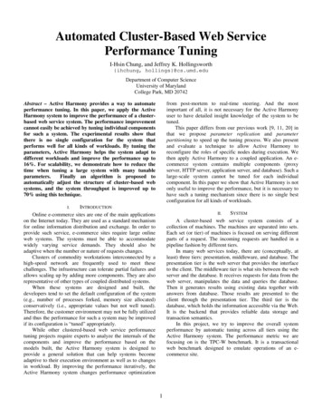
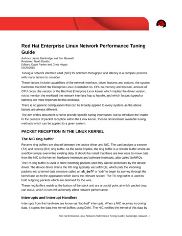
Two Stroke Performance TuningChapter 3Porting and Cylinder ScavengingTODAY, when we take a look down the cylinder of a two-stroke engine, we findits walls literally filled with ports to handle the induction, transfer and exhaust phases ofgas flow through the engine. Those of us who have grown up in the Japanese two-strokeera take it for granted that every cylinder has a huge exhaust port flanked by anythingfrom four to six transfer ports' However, it hasn't always been this way. As far back as1904 Alfred Scott patented his original two-stroke vertical twin. Then in 1906 the FrenchGarard motor appeared with a rotary disc inlet valve. Scott also developed a rotary valveengine in 1912, winning the Senior TT in that year and the following year. However inspite of some very innovative designs being incorporated in two-stroke engines theycontinued to be embarrassingly unreliable and this single factor stifled development rightup until the time of World War II.In the mid-1930s, the DKW company set out to make two-strokes respectable.They were in the business of manufacturing economical two-stroke motorcycles andstood to profit from changing the two-stroke's image. They engaged the services of anengineer named Zoller to build a 250 racer, which ultimately won the Isle of Man TT in1938. This led to the development of a 125 single employing a porting arrangementoriginally invented for two-stroke diesels by German engineer Dr.E.Schneurle. It was thisconcept which ultimately brought success to the two-stroke, both as an economical powersource for transport and as a powerful, light-weight power source for competition.Schneurle's loop-scavenging method, patented in 1925, employed a single exhaust portflanked by two small scavenge or transfer ports, whose air streams were aimed toconverge on the cylinder wall opposite the exhaust (FIGURE 3.1). Being aimed awayfrom the exhaust, the transfer streams had a natural resistance to short-circuiting straightout the exhaust. Earlier designs had used deflector-dome pistons to keep the fuel/aircharge away from the exhaust port. This increased the piston's heat gathering area andmeant that only low power outputs could be aimed for without continually risking pistonseizure.After the war DKW moved to Ingolstadt in West Germany, while their old plantat Zschopau in East Germany was rebuilt as Motorradwerke Zschopau, or MZ. In 1952Walter Kaaden joined MZ to take over development. His early work concentrated onexhaust development and alternate scavenge methods. After much experimentation heproved that the Schneurle loop-scavenge system yielded the best power and reliability.Then in 1957 he added a third transfer port, opposite the exhaust. Its air stream joinedwith the two main transfer ports, directing flow up toward the head (FIGURE 3.2).1
Port and Cylinder ScavengingFig. 3.1: The Schneurle loop scavenge system.2
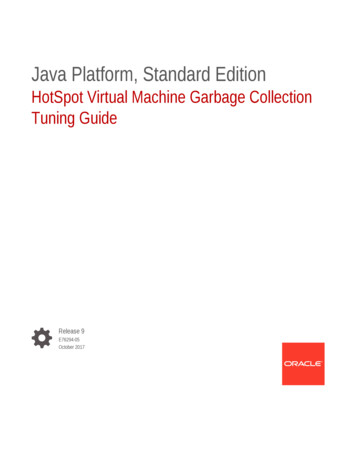
Two Stroke Performance TuningFig. 3.2: Komet K78 TT porting.Contemporary two-stroke technology was introduced initially to Suzuki, and laterto Yamaha in Japan when Ernst Degner defected from East Germany to join Suzuki. Bycombining designs which Degner brought from MZ with Japanese technology in the fieldof metallurgy two-stroke power outputs and reliability took a leap forward. During the'60s Suzuki and Yamaha both won world championships using exotic porting and rotaryvalve induction systems originally developed by DKW and MZ. The Yamaha engineers,however, went one step further. They added a pair of auxiliary transfer ports alongsidethe main transfers, which also directed mixture flow toward the rear of the cylinder andup (FIGURE 3.3). The Japanese engineers then realized, as did Walter Kaaden back in1957, that there was a section of cylinder wall at the rear which could also be filled withanother one or two ports. Transfer flow improved and, as the velocity of the fuel/aircharge entering the cylinder was reduced, mixture loss out of the exhaust was decreased(FIGURE 3.4).3
Port and Cylinder ScavengingFig. 3.3: Yamaha TZ25O D/E/F porting.Fig. 3.4: Suzuki PE175 C porting.4
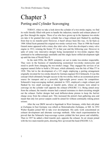
Two Stroke Performance TuningBack in Europe two-stroke engineers were battling excessive ring andcylinder wear, due to the exhaust port width being too great. A narrow port reducedpower but improved reliability. A taller port restored lost power but made the power bandunacceptably narrow. To get around the problem Rotax engineer Dr. Hans Lippitschadded a pair of small auxiliary exhaust ports alongside the large oval exhaust port andabove the main transfers. The two auxiliary ports connect with the main exhaust portbefore the exhaust flange (FIGURE 3.5).Fig. 3.5: Rotax 124 LC porting.Yamaha engineers tackled the problem with their power valve system, which isbasically a mechanism to vary the exhaust port height without narrowing the power band(FIGURE 3.6). As you can see, there is a drum-like valve up against the cylinder wall. Athigh rpm the port is raised, increasing hp while permitting a relatively narrow port widthfor good ring life. At lower speeds the port is lowered, which improves midrange powerand widens the power band. The YZR500 works racer's power valve is controlledelectronically by a battery-powered motor, but the TZ500 production machine utilizes amuch simpler system. Cables run from the tachometer to a centrifugal governor thatraises and lowers the port in harmony with engine rpm. Exhaust duration at higher speeds(i.e., above 10,500 rpm) is 202 , which is about average for a road racer. Low rpmduration is about 180 , or similar to that of a 400 motocross engine.When it comes to modifying a cylinder, the most logical place to start is theexhaust port. A little grinding (or filing) at the sides and top of the port will yield largepower increases if approached correctly. Exhaust ports come in all shapes and sizes; eachtype has its advantages and disadvantages. The port in FIGURE 3.7 is really rectangularbut it is usually referred to as a square port. This is the type that you will find in manylow performance engines. The size of it has to be small so that the rings won't catch onthe top of the port and break. There are two ways this port can be modified: either it canbe widened at the top or it can be ovalized. We have to be careful that the exhaust port5
Port and Cylinder Scavengingdoesn't get too close to the transfers, otherwise there will be excessive loss of fuel/airmixture out of the exhaust. I like to see 8mm separation between these ports, but at timesit is possible to go down to as little as 5mm without ill effect.Fig. 3.6: Yamaha powervalve.Fig. 3.7: Square exhaust port modifications.If port spacing is a problem, you will have no alternative other than to widen theexhaust port at the top. This type of port will give the engine good power from the uppermid-range to maximum hp. When you grind this type of port, the centre of the portshould be 4 to 5 higher than the ends. The reason for this is that when the engine is onthe compression stroke the ring bulges out into the port to its greatest extent just as theport is being closed. However, by raising the centre of the port, the ring has less chanceof hanging up on the edge of the port and breaking because the ends of the port actuallybegin pushing the ring back into the piston groove before the port closes.The elliptical or oval port is the one which I prefer if the port spacing is suitable.It is the type which you will find in most competition two-strokes. The shape of the portis fairly gentle on rings providing it isn't made excessively wide. What is an excessivewidth? Well, I'm not sure; but I have found that a port 0.71 of the bore diameter is a goodcompromise for most road race and motocross engines using ductile iron rings (themaximum safe port size is about 0.65 with brittle cast iron rings). Some tuners take theport size up to 0.75 but ring, piston and port damage is unacceptable. I have been able totake some ports out to 0.73 of the bore size, but this is the exception rather than the rule.6
Two Stroke Performance TuningThe square bridged port is fairly common in large displacement motocross andenduro engines (FIGURE 3.8). It has a very large port area, but then it has to have a largearea as it flows only about 85% as well as an unbridged port of equivalent area. In pastyears this type of port gave a lot of trouble as the bridge would overheat and bulge,pressing hard against the piston and causing a seize-up. However, the bridge gives littletrouble now, providing it is not narrowed down. If heavy bridge-to-piston contact doesoccur, the piston should be relieved where it scuffs against the bridge. As bridged portsare usually quite close to the transfers, there is only one way to increase the port area, andthat is by making the top of the port wider. Modify the port as shown, don't copy the'eyebrows' type exhaust port discussed next.Fig. 3 .8 Bridged exhaust port modification.The 'T' or eyebrows port is seldom seen these days although it was used bySuzuki, Kawasaki and Honda in the past (FIGURE 3.9). This type of port has very littlegoing for it as the sudden change in shape above the main transfers is very harsh on bothpiston and rings. Usually there is very little that can be done to improve this type of port.Bridged exhaust ports can be made very wide, but there is a limit to how far youcan go. With the Suzuki RM125 engines (all models A to T), the maximum width is23mm for the left port window (viewed from the front of the bike) and 25.5mm for theright half of the port. If you go any wider than this, the piston will not be able to seal thecrankcase from the exhaust port because the skirt is relieved around the pin bosses. Thereshould always be sufficient cylinder wall on the sides of both exhaust and inlet ports for a2mm width of piston skirt to bear against and affect a seal.To ensure that you don't go too far in widening the exhaust port, you will have tocarefully scribe the outline of the port windows on the piston skirt with the crankshaftrotated to TDC. Then remove the barrel and measure the distance from the scribed linesto the relieved area around the piston pin bosses. Subtract 2mm from the measurementand this is the amount the port can be increased in width. The amount which can beremoved from bridged inlet ports can be ascertained in a similar way, but with the pistonat BDC.Thus far we have talked about changing the shape and width of the exhaust portbut not the height. Increasing the width of an exhaust port will always result in a powerincrease from the upper mid-range to peak rpm. Usually there will be little or no loss inmid-range power. Raising the port, on the other hand, will always knock bottom end7
Port and Cylinder Scavengingpower. Increasing the duration, the port open period, by just a couple of degrees canmake a bike unrideable in some instances. Just how far you can raise the exhaust port isthe million dollar question everyone would like to know. Some tuners work to a timearea/angle-area formula devised some time back. Frankly, I have found this method ofcalculating port timing completely useless. The geometry and mathematics involved isvery tedious and, when you have finished the entire routine, you find that the answerbears little relationship with present-day two-stroke technology.Fig. 3.9: Honda MT125 RIII porting.Thus far we have talked about changing the shape and width of the exhaust portbut not the height. Increasing the width of an exhaust port will always result in a powerincrease from the upper mid-range to peak rpm. Usually there will be little or no loss inmid-range power. Raising the port, on the other hand, will always knock bottom endpower. Increasing the duration, the port open period, by just a couple of degrees canmake a bike unrideable in some instances. Just how far you can raise the exhaust port isthe million dollar question everyone would like to know. Some tuners work to atimearea/angle-area formula devised some time back. Frankly, I have found this methodof calculating port timing completely useless. The geometry and mathematics involved isvery tedious and, when you have finished the entire routine, you find that the answerbears little relationship with present-day two-stroke technology.I have certain ideas on exhaust port timing, but blindly following my suggestionscould get you into a lot of trouble. My theory is that an engine requires a certain exhaustduration to attain a specific engine speed. Therefore, if an engine is required to makemaximum hp at, say, 12,000rpm, the exhaust duration required will be the same ( 1 )8
Two Stroke Performance Tuningregardless of whether the engine is an 80cc motocross engine or a twin cylinder 250 roadracer. From experience I have a fair idea of just how much duration specific engines need(see TABLE 3.1). However, if the cylinder has a shorter transfer open period than I like,the exhaust duration will have to be reduced, otherwise the bike will be too 'pipey' to ride.On the other hand, I may choose to raise the transfer ports and use the suggested exhausttiming.TABLE 3.1: Exhaust port durationEngine size ApplicationRoad raceMotoXMoto XRoad raceMotoXGo-kartMotoXMoto XRoad raceRoad raceRoad raceRoad raceEnduroEnduroRoad raceEnduroMoto XRoad raceEnduroMoto XEngine speed (rpm)Exhaust duration ( 6-178NOTE: 1 x 100 go-kart refers to a motor with fixed gearing, hence the short exhaust open period.You can easily tie yourself in knots when you tackle cylinder porting. I've knowntuners who have moved exhaust ports up and down and all over the place, searching formore power or a better spread of power. After months of hard work they have achievednothing, basically because the transfer duration was too short and/or the expansionchamber was all wrong. While it may appear rather arbitrary to select an exhaust timingfigure and stick to that, I feel that this is currently the best way to go about two-stroketuning. Then, if the engine does exhibit some undesirable trait, like a narrow powerrange, I change the expansion chamber design to produce the required powercharacteristics. What I'm saying is that expansion chamber design is far more critical thanexhaust port duration. The exhaust open period determines to some extent what themaximum hp will be and at what engine speed it will be produced. The expansionchamber, on the other hand, “adjusts” the power characteristics of the engine at speedsabove and below maximum hp revs.9
Port and Cylinder ScavengingThe formula which I use to calculate exhaust open duration (and transfer duration)is fairly straight forward, but if you do much work on two-strokes it would be moneywell spent if you purchased an electronic calculator with a full scientific function to speedup your calculations. The formula is as follows:where T R L C-ER stroke divided by 2 in mmL con rod length in mm centre to centre(usually the stroke multiplied by 2)C deck clearance in mm(i.e. the distance the piston is below the top of the barrel at TDC)E distance from the top of exhaust port to top of barrelFor example, the exhaust duration of the Morbidelli 125 twin production racer (FIGURE3.10) is as follows:-10
Two Stroke Performance TuningFig. 3 . 1O Morbidelli 125 racer porting.Looking at TABLE 3.1 you can see that the exhaust duration is right where wewant it for peak hp at 13,500-13,700rpm. However, if we were going to modify thisengine extensively by boring the Mikunis 1mm to 29mm and fabricating a new set ofexpansion chambers, we would want the power peak at a little over 14,000rpm, whichwould mean that the duration would have to be increased to 208 to take advantage of theengine's improved breathing. Therefore we would raise the exhaust port 0.35mm. E willnow equal 17.85mm and T will equal 20.5 87 0-17.85 89.65.On some engines fitted with Dykes rings, the top piston ring and not the pistoncrown controls the opening and closing of the exhaust and transfer ports. With theseengines, the exhaust duration is calculated using the same formula, however dimension C(the deck clearance in mm) must be very carefully measured using a depth gaugeotherwise your calculations will be several degrees out. In engines where the Dykes ringactually determines the port opening and closing, dimension C is the distance the ring isbelow the top of the barrel at TDC. Referring back to FIGURE 3.5 you will note that theRotax kart engine appears to have mild porting for a road racer. This engine, in fact, has asingle Dykes ring located very close to the top of the piston. Dimension C is 1.8mm, sowhat looks like motocross porting is truly road race porting. In this case the exhaustduration is 201 .11
Port and Cylinder ScavengingIf you have not had any previous experience tuning two-strokes it is a lot safer tomodify the piston crown to increase exhaust duration rather than raise the port. Once youhave taken the metal away you can't put it back, but fortunately pistons are a good dealless expensive than barrels so all you have to do is keep accurate notes and thenretrogress one step when you have gone too far (FIGURE 3.11). The idea is toprogressively file 0.5mm off the exhaust side of the piston crown until you reach a pointwhere you are happy with the power output. If you accidentally go one step too far, it iseasy to back-track. All you need is a new piston and then, when you modify the 'exhaustport proper, raise it 0.5mm less than the amount you filed off the piston. This type oftuning is back to front to the way in which I prefer to do things, but if you don't want toget involved in expensive and time-consuming expansion chamber fabrication, it is thesafest way out. You will never get the best possible power out of the motor by shiftingthe exhaust port around to work within the limitations imposed by the expansion chamberfitted to your bike. However, this is one of the safer places to begin modifying twostrokes, and even within the boundary set by the stock expansion chamber you shouldend up with an engine which works better than the stock item.Fig. 3.11: Piston modification to increase exhaust open period.When working on the exhaust port, there are two checks which should be made.Firstly, with the piston at BDC, the bottom of the port window should be level with, orlower than, the piston crown, otherwise high speed gas flow will be disrupted (FIGURE3.12). Secondly, in the case of bridged ports, ensure that both halves of the port opensimultaneously. If one side opens a little before the other, gas flow is disrupted to someextent, but worse the pressure waves transmitted to the expansion chamber are of a loweramplitude. This reduces the effectiveness of the exhaust pulses in evacuating andrecharging the cylinder with fresh mixture (FIGURE 3.13).12
Two Stroke Performance TuningFig. 3 .12: Exhaust port must be lower than piston at B.D.C.Fig. 3.13: Both halves of bridged exhaust ports must open simultaneously.If you own a Power Valve type Yamaha there is an additional inspection whichmust be made. Regardless of whether the exhaust port is standard or has been raisedcheck that the power valve opens fully to align with the exhaust port roof. Manually pushthe actuator arm as far as it will go to see if the valve and port align. Usually someadjustment is required. After loosening the adjusting nut and moving the valve to thecorrect position be sure to Loctite the nut so that it does not vibrate loose. Finally verify13
Port and Cylinder Scavengingthat the valve timing is correct with the engine running. This is accomplished by markingthe full extent of the actuator arm travel on the cylinder and revving the engine in shortbursts to see if the valve actually opens that far. If it does not you will have to adjust thevalve to a position slightly higher than the exhaust port roof with the actuator arm pushedto the full open position. Then recheck for full open with the engine running.The only other Power Valve adjustment which is permissible alters the governorspring preload and changes the mid-range rpm valve timing. When spring preload isincreased, lower rpm exhaust duration is increased. As this has the effect of raising topend power and narrowing the power range, it is a modification recommended only forexpert riders on fast circuits. Begin testing with an additional 0.020in. shim fitted behindthe governor spring. If the power comes on too quickly or the power range is too narrow,try a 0.012in. shim.In recent years, the physical size and shape of the exhaust port between the portwindow and the flange where the expansion chamber connects, is under close scrutiny.Attempts are now being made to keep the diameter of the port as small as possible,without impeding the flow of gas out of the cylinder. Whereas the port diameter of atypical 125cc cylinder was 40 to 42mm a few years ago, most exhaust ports for a 125 arenow about 37 or 38mm diameter. This is being done to keep the exhaust pulse wave at ahigh amplitude so that the cylinder is scavenged and recharged more completely. It hasbeen found that allowing the exhaust gases to expand and cool too quickly, as occurswhen the exhaust port is large, actually diminishes the strength of the exhaust pulse.Naturally the tuner's desire to keep the exhaust gas confined so that a strong pulsewave is transmitted through the expansion chamber, has to be balanced against the needfor a free-flowing exhaust passage, which allows the burnt gases to stream unimpeded outof the cylinder. To this end, the exhaust port must be relatively straight, without abruptdirectional changes, to eliminate eddying, and the exhaust flange must match the portperfectly and not change the direction of exhaust flow. When an exhaust port meets theserequirements, gas flow out of the cylinder will be good, even though the port diameter isrelatively small to keep pulse intensity at a high value.A quick look through the exhaust flange and port will indicate how straight theexhaust passage is. However, unless you are very experienced in the science of gas flow,you will not know if the exhaust gases are eddying or not. If you are using castor oil orsome other oil which produced a fair buildup of carbon, you will be able to see where theexhaust port is 'dead'. Any place where there is a layer of carbon in a port which isbasically carbon-free is a place of little flow activity. In such an area you can be fairlycertain that the gases are eddying and disrupting flow out of the cylinder.At times, the low pressure area can be eliminated by grinding metal out of theport, but more often than not the port will require welding up. The exhaust port illustratedin FIGURE 3.14 is a particularly nasty one. The flange changes the direction of flow veryabruptly, which produces an eddy current in the top of the flange. Also the floor of theport drops away too quickly, causing eddying in this area.14
Two Stroke Performance TuningFig. 3 .14: Exhaust port must be correctly modified to assist flow.There are two ways to tackle the problem with the flange. The roof of the portmay be ground higher and the flange raised to reduce the kink in the port's roof. On theother hand a new flange can be fabricated with the roof in line with the roof of theexhaust port. Either way, the floor of the port, and perhaps the floor of the flange too, willhave to be welded up to improve the profile. The aluminum floor naturally will have tobe argon-arc welded. Fill in only a little at a time and allow the cylinder plenty of time tocool between each run, otherwise it will distort.15
Port and Cylinder ScavengingAs shown in FIGURE 3.15 the exhaust flange may be out of line when viewedfrom above. Again this must be corrected by fabricating a new flange which aligns withthe exhaust port.From the aspect of two-stroke engine design, I feel that the transfer ports are themost important. Unfortunately, from the average tuner's viewpoint, the transfers are themost difficult to modify and the least understood. By definition, the transfer ports havethe job of transferring the fuel/air mixture from the crankcase into the cylinder. Thatsounds simple enough but, after we consider all of the factors involved, you will betterappreciate what a mammoth task this really is.In an average racing engine the induction cycle will take place during around190 of crankshaft rotation. The exhaust cycle will occur over a period of 200 . Thetransfer phase, however, has to be completed through 130 of crankshaft movement. Notonly do the transfers have an extremely short time in which to recharge the cylinder withfuel/air mixture, they must also control the flow pattern of the charge to prevent mixtureloss out of the exhaust, and drive exhaust gases from the rear of the cylinder towards theexhaust port.Fig. 3.15: Flange must be in line with exhaust port to stop eddying.16
Two Stroke Performance TuningDuring the '60s, when Suzuki and Yamaha dominated Grand Prix racing, theirengineers revived a myth which surfaced from the development of BSA Bantam andVilliers engines for racing just after the war. These engines had massive spaces in thecrankcase and tuners reasoned, rightly enough, that filling the crankcase with a variety of'staffers' would reduce crankcase volume and hence increase crankcase compressionwhen the piston descended to BDC. Increasing crankcase compression naturally enoughresults in higher crankcase pressure which, all else being equal, raises transfer flow andimproves maximum hp output. Tuners cited the reason for this as being due to thetransfer streams erupting under considerable pressure into the cylinder. Because of thisthe fuel/air charge tended to behave like a wedge on entering the cylinder. It didn't breakup and mingle with the exhaust gases, but pushed them out of the cylinder withconsiderable force.So effective was this method of cylinder scavenging that the fuel/air 'wedge' wasactually being partly lost out of the exhaust before the port closed. Two-stroke tunersovercame this problem by opening the transfer ports later and closing them earlier,reducing traditional transfer duration from 130 down to 120 . Because of more fuelcharge being contained within the cylinder, power increased. This encouraged engineersto further increase crankcase compression and reduce the transfer open period to less than110 . Horsepower again rose, instilling in Japanese engineers the idea that dominance inGrand Prix racing would depend on them reducing transfer duration to contain chargeloss out of the exhaust and increasing crankcase compression to ensure efficient pumpingof the fuel/air mixture from the crankcase into the cylinder.The theory sounds good, but in practice there were problems. True, power outputsrose to levels previously unknown from two-strokes, but the power bands became razorthin and engine speeds rose to incredible levels. Not to be deterred, the Japaneseengineers embarked on a scheme of cylinder size reduction to enable very high rpm to beattained reliably. Again power levels increased, providing a further stimulus to reducecylinder displacement. This led to the development of such machines as the three cylinder50cc Suzuki and the four cylinder Yamaha 125 which produced 40hp at 18,000rpm. Atthis time road racers had from ten to eighteen gears, such were the power characteristicsof these engines.The problem was that in spite of the very limited transfer open periods employed,at lower engine speeds too much charge was being lost out of the exhaust. This occurredbecause the transfer charge entered the cylinder under so much pressure that it had timeto spurt right out of the exhaust at low rpm. Hence little power was produced at speedsbelow maximum hp revs. At higher rpm, power was again restricted, due to the transferports being too small to flow a larger volume of fuel/air mixture in the available time.Today, the very same problem occurs when very short transfer periods areemployed. Generally, you will find that bikes which are 'pipey', coming onto the powertoo quickly or exhibiting a narrow power range, are that way because the transfer portsare too low (i.e., short duration) or because the ports are incorrectly aimed.17
Port and Cylinder ScavengingFortunately, manufacturers have mostly got away from the idea of using highcrankcase compression to push the fuel charge through the transfers into the cylinder, sowe can forget about crankcase compression and concentrate on the transfer ports.However, for those who are interested, primary compression or crankcase compression iscalculated using this formula:-To measure the crankcase volume (CCV), first turn the engine onto its side, withthe inlet port facing up, and rotate the crank to bring the piston up to TDC. Then, using aburette filled with liquid paraffin (kerosene) and engine oil, mixed 50/50, fill thecrankcase up to the cylinder wall face of the inlet port. If this equals, say, 425cc, and theengine has a 125cc cylinder, the primary compression ratio will be 1.42:1.At this time, instead of relying solely on crankcase pressure to push the fuel/airmix into the cylinder, we also use the suction wave produced in the expansion chamber topull the intake charge up through the transfers. If we use an expansion chamber withshallow tapers, maximum power will be suppressed, but the suction wave will be activein drawing mixture into the cylinder over a wide rpm range. On the other hand a chamberwith steeper cones will produce a stronger suction wave, raising peak hp, but it will beeffective over a much narrower rev range.Obviously the longer we leave the tran
originally invented for two-stroke diesels by German engineer Dr.E.Schneurle. It was this concept which ultimately brought success to the two-stroke, both as an economical power source for transport and as a powerful, light-weight power source for competition. Schneurle's loop-scavenging