Transcription
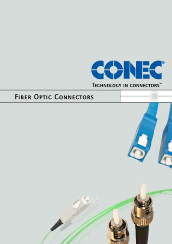
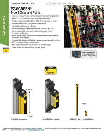
EZ-SCREEN (TYPE 4 & TYPE 2)PICO-GUARD FIBER OPTIC (TYPE 4)EZ-SCREEN MACHINE SAFETYType 4 Grids and PointsACCESSORIES Suited to a variety of access and long-range perimeter guarding applications Uses 1-, 2-, 3- or 4-beams to protect personnel and machinery Operates in ranges from 0.8 to 20 m or 15 to 70 m, depending on model Displays operating status, configuration and error codes Includes blocked beam zone indicators Features user-configurable trip or latch outputs, and Scan Code 1 or 2 Can be combined with other devices, such as mirrors and Points,for a custom configuration Resists impact, twisting and abusive environments with a durable aluminumhousing and metal endcaps Exceeds OSHA/ANSI Control Reliability requirements and is certified to cULusNIPF, and certified to Type 4 and Category 4 Offers optional lens shields and enclosures for added durability Easy to hookup and flexible machine interface optionspage500Interface multiple deviceswith the SC22-3 SafetyController. See page 526onlineAUTOCAD, STEP,IGES & PDF55.0 mmFull ViewL52.0 mmEZ-SCREEN Grid SystemsEZ-SCREEN Point SystemsEZ-SCREEN GridEZ-SCREEN PointCourtesy of Steven Engineering, Inc.-230 Ryan Way, South San Francisco, CA 94080-6370-Main Office: (650) 588-9200-Outside Local Area: (800) 258-9200-www.stevenengineering.com494More information online at bannerengineering.com
EZ-SCREEN Grid & Point Systems, 24V Length (L)OutputEmitterSGE3-533Q8E0.8 - 20 mPair †SGP3-533Q88ESGR3-533Q8E1251 mm1066 mm3-BEAM533mmModelsReceiverSGXLE3-533Q8E15 - 70 mPhotoelectricsSensorsFiber OpticSensorsSpecial PurposeSensorsMeasurement &Inspection SensorsVisionWirelessSGXLP3-533Q88ELighting &IndicatorsSafetyLight ScreensSGE4-300Q8E0.8 - 20 m900 mmSGR4-300Q8E1084 mm4-BEAM300mm15 - 70 mSGXLE4-300Q8ESGXLP4-300Q88E0.8 - 20 mSGE3-400Q8ESGP3-400Q88E800 mmSGR3-400Q8E984 mm3-BEAM400mm15 - 70 m2 PNP OSSD(Trip/Latchselectable)8-pin Euro QD0.8 - 20 mSGXLE3-400Q8ESGXLP3-400Q88ESafetyLaser ScannersFiber OpticSafety SystemsSafety Controllers &ModulesSafety Two-HandControl ModulesSafety InterlockSwitchesEmergency Stop &Stop R2-584Q8E768 mm584 mm2-BEAM584mmSGP4-300Q88E15 - 70 mSGXLE2-584Q8ESGXLP2-584Q88E0.8 - 20 mSGE2-500Q8ESGP2-500Q88EEZ-SCREEN500 mmSGR2-500Q8E684 mm2-BEAM500mm15 - 70 mSGXLE2-500Q8ESGXLP2-500Q88E0.8 - 20 mSPE1Q8ESPP1Q88ETYPE 414 or 30 mmTYPE 4Low Profile14 or 25 mmTYPE 230 mmGridS & PointsPICO-GUARDN/A1-BEAM1-BEAMSPR1Q8E149 mm15 - 70 mSPXLE1Q8ESPXLP1Q88EA model with a QD requires a mating cordset (see page 500). For emitters and receivers with a wiring terminal chamber, remove the Q8E or Q88E from the model number (example, SGE4-300). For an emitter with a 5-pin Mini QD and TEST function,replace Q8E with Q5 on emitter model numbers (example, SGE4-300Q5) and Q88E with Q85 on pair model numbers (example, SGP4-300Q85).For emitters with a 3-pin Mini QD, replace Q8E with Q3 (example, SGE4-300Q3); and for receivers with an 8-pin Mini QD, replace Q8E with Q8 on model numbers (example, SGR4-300Q8);or for a pair replace Q88E with Q83 (example, SGP4-300Q83).†A pair includes an emitter and receiver (example, SGP4-300Q88E). Emitters (example, SGE4-300Q8E) and receivers (example, SGR4-300Q8E) are also sold separately.Courtesy of Steven Engineering, Inc.-230 Ryan Way, South San Francisco, CA 94080-6370-Main Office: (650) 588-9200-Outside Local Area: (800) 258-9200-www.stevenengineering.comMore information online at bannerengineering.com495
EZ-SCREEN (TYPE 4 & TYPE 2)PICO-GUARD FIBER OPTIC (TYPE 4)EZ-SCREEN Grid KitsMACHINE SAFETYYou can purchase a kit that contains an emitter and receiver of equal length and beam spacing; brackets; and optionalinterfacing solution and quick-disconnect cordsets. Detailed information about individual kit components is as follows.ACCESSORIESpage500 Emitter and ReceiversPage 495 Interfacing Options501 Cordsets500 Brackets500To Order:1. Choose model range, number of beams and beam spacing.2. Choose the connection: Integral M12/Euro-Style QD or intergalMini-Style QD3. Choose an optional interfacing solution, such as an IM-T-9A or -11interfacing model.See www.bannerengineering.com for complete information and a currentlisting of accessories and options for kitting components. Call factory withquestions regarding accessories.4. Choose one cordset for each sensor or two cordsets for a pair.M12/Euro QD models (example, SGK4-300Q88E) requiremating 8-pin M12/Euro QD cordsets, such as:- QDE cordset with flying leads- DEE2R double-ended cordset- CSB series splitter cordsetMini QD models (example, SGK4-300Q83) requiremating cordsets, such as:- QDS cordset with flying leadsKit Model KeyModel StyleKit No. of BeamsS GModel StyleSG Safety GridSGXL Safety Grid LongRangeK4BeamConnectionSpacing3 0 0KitK KitNo. of Beams2 two beams3 three beams4 four beamsBeam Spacing300 mm400 mm500 mm533 mm584 mmReceiver & Emitter QD OptionsBlank Receiver and emitter with wiring terminal chamberQ85 Receiver with integral 8-pin Mini-style QDEmitter with integral 5-pin Mini-style QD with TestQ83 Receiver with integral 8-pin Mini-style QDEmitter with integral 3-pin Mini-style QDQ88E Receiver and emitter with integral 8-pin M12/Euro QDQ 8 8EInterfacingOptionsQD CordsetLength Options1R E 2 5QD Cordset Length ExamplesRE15 4.6 m, 2 eachRE25 7.6 m, 2 eachR15E25 4.6 m (Receiver) & 7.6 m (Emitter)R25E15 7.6 m (Receiver) & 4.6 m (Emitter)DD1 0.3 DEE2R-81D, 2 eachC1D15 CSB-M1281M1281 (Receiver)DEE2R-815D (8-pin Emitter)C8D25 CSB-M1288M1281 (Receiver)DEE2R-825D (8-pin Emitter)CU25D25 CSB-UNT825M1281 (Receiver)DEE2R-825D (8-pin Emitter)Interfacing Examples1 IM-T-9A Interface Module, 1 each (3 NO)2 IM-T-11A Interface Module, 1 each (2 NO/1 NC)3 11-BG00-31-D-024 Contactors (10A), 2 each4 BF1801L-024 Contactors (18A), 2 each5 EZAC-R9-QE8 AC Interface Box (3 NO), 1 each6 E ZAC-R11-QE8 AC Interface Box (2 NO/1 NC), 1 eachNOTE: See notes under model number table. Not all combinations are listed below. Contact Banner Engineering Corp. for additional informationand/or verification of valid kit model numbers.Courtesy of Steven Engineering, Inc.-230 Ryan Way, South San Francisco, CA 94080-6370-Main Office: (650) 588-9200-Outside Local Area: (800) 258-9200-www.stevenengineering.com496More information online at bannerengineering.com
EZ-SCREEN Point KitsYou can purchase a kit that contains an emitter and receiver of equal length; brackets; and optional interfacingsolution and quick-disconnect cordsets. Detailed information about individual kit components is as follows. Emitter and ReceiversPage 495 Interfacing Options501 Cordsets500 Brackets500PhotoelectricsSensorsFiber OpticSensorsSpecial PurposeSensorsMeasurement &Inspection SensorsVisionWirelessLighting &IndicatorsSafetyLight ScreensSafetyLaser ScannersTo Order:1. Choose model and range.2. Choose the connection: Integral M12/Euro-Style QD or intergalMini-Style QD3. Choose an optional interfacing solution, such as an IM-T-9A or -11interfacing model.See www.bannerengineering.com for complete information and a current listingof accessories and options for kitting components. Call factory with questionsregarding accessories.Fiber OpticSafety Systems4. Choose one cordset for each sensor or two cordsets for a pair.M12/Euro QD models (example, SPK1-Q88E) requiremating 8-pin M12/Euro QD cordsets, such as:- QDE cordset with flying leads- DEE2R double-ended cordset- CSB series splitter cordsetMini QD models (example, SPK1-Q83) requiremating cordsets, such as:- QDS cordset with flying leadsSafety Controllers &ModulesSafety Two-HandControl ModulesSafety InterlockSwitchesEmergency Stop &Stop ControlACCESSORIESpage500EZ-SCREENKit Model KeyModel StyleKitNo. of BeamsConnectorSPModel StyleSP Safety PointSPXL Safety PointLong RangeK1KitK KitNo. of Beams1 one beamReceiver & Emitter QD OptionsBlank Receiver and emitter with wiring terminal chamberQ85 Receiver with integral 8-pin Mini-style QDEmitter with integral 5-pin Mini-style QD with TestQ83 Receiver with integral 8-pin Mini-style QDEmitter with integral 3-pin Mini-style QDQ88E Receiver and emitter with integral 8-pin M12/Euro QDNOTE: See notes under model table. Not all combinations arelisted below. Contact Banner Engineering Corp. for additionalinformation and/or verification of valid kit model numbers.Q88EInterfacingOptionsQD CordsetLength Options1RE25TYPE 414 or 30 mmTYPE 4Low Profile14 or 25 mmTYPE 230 mmGridS & PointsPICO-GUARDQD Cordset Length ExamplesRE15 4.6 m, 2 eachRE25 7.6 m, 2 eachR15E25 4.6 m (Receiver) & 7.6 m (Emitter)R25E15 7.6 m (Receiver) & 4.6 m (Emitter)DD1 0.3 DEE2R-81D, 2 eachC1D15 CSB-M1281M1281 (Receiver)DEE2R-815D (8-pin Emitter)C8D25 CSB-M1288M1281 (Receiver)DEE2R-825D (8-pin Emitter)CU25D25 CSB-UNT825M1281 (Receiver)DEE2R-825D (8-pin Emitter)Interfacing Examples1 IM-T-9A Interface Module, 1 each (3 NO)2 IM-T-11A Interface Module, 1 each (2 NO/NC)3 11-BG00-31-D-024 Contactors (10A), 2 each4 BF1801L-024 Contactors (18A), 2 each5 EZAC-R9-QE8 AC Interface Box (3 NO), 1 each6 E ZAC-R11-QE8 AC Interface Box (2 NO/1 NC), 1 eachCourtesy of Steven Engineering, Inc.-230 Ryan Way, South San Francisco, CA 94080-6370-Main Office: (650) 588-9200-Outside Local Area: (800) 258-9200-www.stevenengineering.comMore information online at bannerengineering.com497
EZ-SCREEN (TYPE 4 & TYPE 2)PICO-GUARD FIBER OPTIC (TYPE 4)MACHINE SAFETYEZ-SCREEN Grid & Point SpecificationsSupply Voltage (V in)24V dc 15%, 10% max. rippleSupply CurrentEmitter: 150 mA max.Receiver: 500 mA max., exclusive of OSSD1 and OSSD2 loads (up to an additional 0.5A each)Short Circuit ProtectionAll inputs and outputs are protected from short circuits to 24V dc or dc common (except Emitter AUX power connections)Response Time24 milliseconds or less from interruption of light grid beam to safety outputs going to OFF-stateEDM Input 24V dc signals from external device contacts can be monitored (single-channel, dual-channel or no monitoring) via EDM1 andEDM2 terminals in the receiver. Monitored devices must respond within 200 milliseconds of an output change.Reset InputThe Reset input must be high (10 to 30V dc at 30 mA) for 0.25 to 2 seconds and then low (less than 3V dc) to reset the receiver.Remote Test Input(optional- available only on certainmodels)Test mode is activated either by applying a low signal (less than 3V dc) to emitter TEST1 terminal for a minimum of 50 milliseconds,or by opening a switch connected between TEST1 and TEST2 terminals for a minimum of 50 milliseconds. Beam scanning stops tosimulate a blocked condition. A high signal (10 to 30V dc, 35 mA inrush, 10 mA max.) at TEST1 terminal deactivates Test mode andallows the emitter to operate normally. TEST1 and TEST2 are factory jumpered on models with wiring chamber.Safety OutputsTwo diverse-redundant solid-state 24V dc, 0.5 A max. sourcing OSSD (Output Signal Switching Device) safety outputs.(Use optional interface modules for ac or larger dc loads.) Capable of the Banner “Safety Handshake.”ON-State voltage: Vin-1.5V dcOFF-State voltage: 1.2V dc max.Max. load resistance: 1000 ΩMax. load capacitance: 0.1 µFOSSD test pulse width: 250 microsecondsOSSD test pulse period: 6 millisecondsControls and AdjustmentsEmitter: Scan code selection: 2-position switch (code 1 or 2). Factory default position is 1.Receiver: Scan code selection: 2-position switch (code 1 or 2). Factory default position is 1.Trip/latch output selection: redundant switches. Factory default position is L (latch)EDM/MPCE monitor selection: redundant switches select between 1- or 2-channel monitoring.Factory default position is 2.Emitter/Receiver Operating RangeShort-range models: 0.8 m to 20 mLong-range models: 15 m to 70 mRange decreases with use of mirrors and/or lens shields.Beam SpacingModel SG.4-300: 300 mmModel SG.2-500: 500 mmModel SG.2-584: 584.2 mmBeam Diameter25 mmAmbient Light Immunity 10,000 lux at 5 angle of incidenceStrobe Light ImmunityTotally immune to one Federal Signal Corp. “Fireball” model FB2PST strobeEmitter ElementsInfrared LEDs, 880 nm at peak emissionEffective Aperture Angle (EAA)Meets Type 4 requirements per IEC 61496-2Short-range models: 2.5 @ 3 mModel SG.3-400: 400 mmModel SG.3-533: 533.4 mmLong-range models: 2.5 @ 15 mEnclosureMaterials: Extruded aluminum housings with yellow polyester powder finish and well-sealed, rugged molded PBT end caps,acrylic lens coverRating: NEMA 4, 13; IP65Operating ConditionsTemperature: 0 to 50 CShock and VibrationEZ-SCREEN systems have passed vibration and shock tests according to IEC 61496-1/-2. This includes vibration (10 cycles) of10-55 Hz at 0.35 mm single amplitude (0.70 mm peak-to-peak) and shock of 10 g for 16 milliseconds (6,000 cycles).Relative humidity: 95% (non-condensing)Moreon nextpageCourtesy of Steven Engineering, Inc.-230 Ryan Way, South San Francisco, CA 94080-6370-Main Office: (650) 588-9200-Outside Local Area: (800) 258-9200-www.stevenengineering.com498More information online at bannerengineering.com
EZ-SCREEN Grid & Point SpecificationsStatus Indicators(cont’d)7-Segment Diagnostic Indicators, Both Emitter and ReceiverDash (–) System is OKError Codes See product manuals (p/n 68410 or 68413) for code definitions and recommended actionScan code setting Appears during power-up or after scan code is changed.(C1 or C2) (Temporary indication; normal display resumes within a few seconds.)Emitter: One bi-color (red/green) Status indicatorGreen steady RUN modeGreen single flashing TEST modeRed single flashing LockoutOFF No power to sensorReceiver: Two System Status indicators, plus one bi-color (red/green) Beam Status indicator for each beamYellow Reset IndicatorON steady RUN modeDouble flashing Waiting for manual reset after power-upSingle flashing Waiting for manual latch resetOFF No power to sensor or system is not ready for operationBi-Color (Red/Green) Status IndicatorGreen steady Outputs ONRed steady RUN mode, outputs OFFRed single flashing LockoutOFF No power to sensor or system is not ready for operationBi-Color (Red/Green) Beam Status IndicatorsGreen steady Clear beam, strong signalGreen flickering Clear beam, weak signalRed steady Beam blockedOFF No power to sensor or no scanningMounting HardwareEmitter and receiver each are supplied with a pair of swivel end mounting brackets. Mounting brackets are 8-gauge cold-rolledsteel, black zinc finish.Cables and ConnectionsCables are user-supplied. Wiring terminals accommodate one 22 to 16 ga. wire or two wires up to 18 ga.; Pg 13.5 wiringchamber access port capacity varies, depending on cable gland or strain relief fitting used. Supplied cable gland is for a cablediameter of 6 to 12 mm.Design StandardsDesigned to comply with Type 4 per IEC 61496-1, -2; Type 4 per UL 61496-1/-2; Category 4 per ISO 13849-1 (EN 954-1)PhotoelectricsSensorsFiber OpticSensorsSpecial PurposeSensorsMeasurement &Inspection SensorsVisionWirelessLighting &IndicatorsSafetyLight ScreensSafetyLaser ScannersFiber OpticSafety SystemsSafety Controllers &ModulesSafety Two-HandControl ModulesSafety InterlockSwitchesEmergency Stop &Stop ControlEZ-SCREENTYPE 414 or 30 mmTYPE 4Low Profile14 or 25 mmTYPE 230 mmGridS & PointsPICO-GUARDCertificationsWiring DiagramsWD011, WD012, WD013, WD014, WD015, WD016, WD017, WD018, WD019 (pp. 781-786)Courtesy of Steven Engineering, Inc.-230 Ryan Way, South San Francisco, CA 94080-6370-Main Office: (650) 588-9200-Outside Local Area: (800) 258-9200-www.stevenengineering.comMore information online at bannerengineering.com499
EZ-SCREEN (TYPE 4 & TYPE 2)PICO-GUARD FIBER OPTIC (TYPE 4)MACHINE SAFETYCordsetsEuro QDEuro QD SplitterEuro QD–Double-EndedMini QDSee page 690See page 693See page 691See page 700Length8-Pin4.57 Pin0.31 mDEE2R-81D3-Pin4.75 mQDS-315C5-Pin8-PinQDS-515CQDS-815C7.62 mQDE-825D0.30 mCSB-M1281M12810.91 mDEE2R-83D7.62 mQDS-325CQDS-525CQDS-825C15.3 mQDE-850D2.50 mCSB-M1288M12812.44 mDEE2R-88D15.2 mQDS-350CQDS-550CQDS-850C22.9 mQDE-875D4.60 mCSB-M12815M12814.57 mDEE2R-815D22.9 mQDS-375C–30.5 mQDE-8100D7.60 mCSB-M12825M12817.62 mDEE2R-825D30.5 mQDS-3100C–7.60 mCSB-UNT825M128115.2 mDEE2R-850D22.9 mDEE2R-875D30.5 mDEE2R-8100DAdditional cordset information available.See page 679.QDS-875C–* For connection to safety BUS gateway/node a “smart” self-monitoredsafety module, safety controller or safety PLC see page 691.BracketsGrids & Points–Type 4pg. 628pg. 630EZA-MBK-1*pg. 631EZA-MBK-3Points–Type 4pg. 629EZA-MBK-9pg. 630EZA-MBK-2**pg. 630EZA-MBK-4EZA-MBK-5Additional bracket information available.See page 620.* Standard brackets included with emitter/receiver.** One EZA-MBK-2 adapter bracket kit required per sensor when mounting to MSA series stands.NOTE: See page 501 for interfacing solutions.Replacement PartsModelDescriptionEZA-AP-1Access port plug with o-ringEZA-CP-13Pg13.5 plug with o-ringEZA-ECE-1Emitter wiring chamber end cap (with gasket, captive screws, 3 plugs with o-rings, terminal block)EZA-ECR-1Receiver wiring chamber end cap (with gasket, captive screws, 3 plugs with o-rings, terminal block)EZA-SW-1Spanner wrench for Grid and PointEZA-TBE-1Emitter terminal blockEZA-TBR-1Receiver terminal blockMGA-K-1Replacement key for switch MGA-KS0-1MGA-KS0-1Panel-mount keyed normally open reset switchSMA-MBK-1SSM Series Mirror Bracket KitSTP-3Specified test piece, 45 mm dia.Note: See Installation manual p/n 112852 for complete list of replacement parts and accessories.STANDSMIRRORSPAGE 722PAGE 726LENS SHIELDSPAGE 732INTERFACEENCLOSURESPAGE 501PAGE 728Courtesy of Steven Engineering, Inc.-230 Ryan Way, South San Francisco, CA 94080-6370-Main Office: (650) 588-9200-Outside Local Area: (800) 258-9200-www.stevenengineering.com500More information online at bannerengineering.com
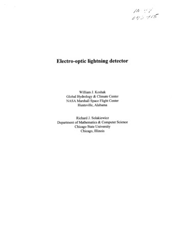
WD011AccessoriesEZ-SCREEN System (Type 4)EmitterReferenceReceiver with 2 Solid-State OSSDs, 2 FSDs and 2-Channel EDMHookupsWiring Diagrams 24V dcGlossary0V dcInternational RepsPage 469Models 24V dc0V dcEZ-SCREENReceiver E Z-SCREEN Grid & Point withterminal chamber hookup (Models with M12/Euro QD,see WD001)EmitterPE 1dc Com 2EZ-SCREEN 24V dc 3PE 1(Not Used) 4dc Com 2RESET 5 24V dc 3Open to testTEST2 4orTEST1 5EDM21) TEST inputbe 7 mustjumpered if not used. OSSD1Typically a Normally 8Open switch heldclosed.OSSD29See Section 3.7.4 forinformation on TESTSingle-Channelinput and hookup.Safety Stop Circuit(Not Used) 6 24V dc 7Auxiliary powerconnectionsdc Com 8ResetEDM1 6PE 9FSD2*FSD1*Dual-ChannelSafety Stop Circuit* Installation of trand FSD2 is recNOTE: Do not exceed OSSD maximum load capacitance specification.Wiring diagrams arefor information only.See appropriatemanuals for all specific warnings,cautions and information for use.Wiring diagrams arefor information only.See appropriatemanuals for all specific warnings,cautions and information for use.!!* Arc Suppressors.See manual for specific warnings.WD012EZ-SCREEN System (Type 4)1-Channel EDM of IM-T-9A Interface Module 24V dc0V dc2-Channel EDM of IM-T-9A Interface Module 24V dc0V dcEZ-SCREENReceiverEZ-SCREENReceiverPE 1dc Com 2 24V dc 3 24V dc 3(Not Used) 4(Not Used) 4Page 469ModelsRESET 5 E Z-SCREEN Grid & Point withterminal chamber hookup (Models with M12/Euro QD,see WD003-WD006) RESET 5ResetEDM1 6EDM1 6EDM2 7EDM2 7 OSSD1 8 OSSD2 9IM-T-9AIM-T-9AS4S3 K2S1 S2 Y113 23 33 Y2K1 S1S4S2S3 K2MachineControlY2Y323243334* Arc See manualspecific2) See forSection3.7.3 warnings.forinformation on EDMinput and hookup.S2Y3Y4MPCE2 *Feedback (optional)Y3 S3 S4S1Y1141) See Section 3.5 for moreinformation on Resetinput and hookup.Suppressors. Y213Y4 14 24 34K1Y1Y4IM-T-9AResetOSSD1 8OSSD2 9IM-T-9ATerminal LocationsPE 1dc Com 2!MPCE1 *MachineControlWiring diagrams are* Installation of transientforsuppressorsinformationacrossonly.the coils of MPCE1 and MPCE2 isSee appropriaterecommended (see Warning).manuals for all specific warnings,cautions and information for use.131423243334Feedback (optional)1) See Section 3.5 for moreinformation on Resetinput and hookup.Suppressors.* Arc 2) See3.7.3forSee manualforSectionspecificwarnings.information on EDMinput and hookup.MPCE2 *!MPCE1 *Wiring diagrams arefor information only.* Installation of transientsuppressorsacrossSeeappropriatethe coilsmanualsof MPCE1forandis warnings,allMPCE2specificrecommended (see Warning).cautions and information for use.Moreon nextpageCourtesy of Steven Engineering, Inc.-230 Ryan Way, South San Francisco, CA 94080-6370-Main Office: (650) 588-9200-Outside Local Area: (800) 258-9200-www.stevenengineering.comMore information online at bannerengineering.com781
WIRING DIAGRAMSHOOKUPSREFERENCE CHARTSGLOSSARYINTERNATIONAL REPSWD013EZ-SCREEN AC Interface BoxREFERENCEEZAC-R9-QE8 – Hard-Wired with 3 NO and EDMP42-ch. 1-ch.EDMX1X2Page 736X3ModelsX4Connections(Hand Wired)132143234245336347451P5 23LEZAC-R9-QE8N100 - 230V ac(Line) P53(Neutral) P52(Gnd) P511/2 NPT threadsfor outputs2P3 38P2P1 EZAC-R9-QE811MachineControlMPCE1K1K2*1/2 NPT threadsfor AC inputs8-pin femaleEuro-style QDto emitter/receiver13142324MPCE23334*2-Channel EDM HookupX12-ch. 1-ch.(EDM1)Monitoring ContactsMPCE1X2X3(EDM2)X12-ch. 1-ch.(EDM1)MPCE2X41-Channel EDM HookupMonitoring ContactsMPCE1X2MPCE2X3(EDM2)X4X12-ch. 1-ch.(EDM1)No EDMX2X3(EDM2)* Arc Suppressors. See manual for specific warnings.X4Wiring diagrams arefor information only.See appropriatemanuals for all specific warnings,cautions and information for use.!Moreon nextpageCourtesy of Steven Engineering, Inc.-230 Ryan Way, South San Francisco, CA 94080-6370-Main Office: (650) 588-9200-Outside Local Area: (800) 258-9200-www.stevenengineering.com782More information online at bannerengineering.com
WD014AccessoriesEZ-SCREEN AC Interface BoxReferenceEZAC-R11-QE8 – Hard-Wired with 2 NO, 1 NC and EDMHookupsWiring DiagramsGlossaryInternational RepsPage 736Models EZAC-R11-QE8Connections(Hand Wired)1/2 NPT threadsfor outputs1/2 NPT threadsfor AC inputs8-pin femaleEuro-style QDto emitter/receiverWiring diagrams arefor information only.See appropriatemanuals for all specific warnings,cautions and information for use.!* Arc Suppressors. See manual for specific warnings.Moreon nextpageCourtesy of Steven Engineering, Inc.-230 Ryan Way, South San Francisco, CA 94080-6370-Main Office: (650) 588-9200-Outside Local Area: (800) 258-9200-www.stevenengineering.comMore information online at bannerengineering.com783
WIRING DIAGRAMSHOOKUPSREFERENCE CHARTSGLOSSARYINTERNATIONAL REPSWD015EZ-SCREEN System (Type 4)REFERENCEEZAC-R15A-QE8-Q583-Mini-Style QD with 1 NO, 1 SPDT and 1-Channel EDMLEZAC-R15A-QE8-QS832(Neutral) P5Page 736Models(Gnd) P5 EZAC-R15A-QE8-QS832BuNBnL113-Pin Mini-Style Power ConnectorMale Face ViewGreen/YellowwireBrownwire33(Line) P5N100 - 230V acPinGn/Ye7BluewireMating Cordset: /PE2BrownLine3BlueNeutral8-Pin Mini-Style Output ConnectorMale Face ViewGn/YeGreen/YellowConnections(8-Pin Mini)K15K22324431328Bn8-pin femaleEuro-style QDto emitter/receiverMating Cordset: QDS-8.C*N.C. Aux (see Warning)BuX13(EDM1) X22LampN.O.Or 24V dc N.O.2Orange/Black 24V dc (EDM)3OrangeEDM4WhiteN.O. (to load)5BlackN.O. (to load)6BlueCommon7Green/YellowGnd/PE8VioletN.C. Aux.Monitoring ContactsX3Wiring diagrams arefor information only.See appropriatemanuals for all specific warnings,cautions and information for use.!(EDM2) X4†WhiteVioletMPCE2N.O. (to load)ViBlueBlackOrangeN.O.Wh63-pin maleMini-stylefor AC inputsN.O. (to load)Orange/Black*114138-pin maleMini-stylefor outputsBkBrownMPCE1Arc Suppressors. See manual for specific warnings.WD016EZ-SCREEN AC Interface BoxEZAC-R8N-QE8-QS53 – Mini-Style QD with 1 NO, 1 NC and Power MonitoringLEZAC-R8N-QE8-QS53(Neutral) P523(Line) P532(Gnd) P511Page 736Models EZAC-R8N-QE8-QS533Connections(5-Pin Mini)K15K2135-pin maleMini-stylefor outputsN3-Pin Mini-Style Power ConnectorMale Face View100 - 230V ac14231Green/YellowwireBuNBnLGn/YeMPCE1 MPCE2BrownwireMating Cordset: /YeWhN.O. (1b)5-Pin Mini-Style Output ConnectorMale Face ViewMPCE1BlackBlue*BkN.O. (1a)WhiteBrownGreen/YellowMating Cordset: QDS-5.C2431Bluewire24BuN.C. (2b)MPCE2*BnN.C. (2a)PinColorFunction1BlackN.O. (1a)2BlueN.C. (2a)3Green/YellowGnd/PE4BrownN.C. (2b)5WhiteN.O. (1b)X13-pin maleMini-stylefor AC inputs8-pin femaleEuro-style QDto emitter/receiver(EDM1) X2X3(EDM2) X4Wiring diagrams arefor information only.See appropriatemanuals for all specific warnings,cautions and information for use.!Moreon nextpageCourtesy of Steven Engineering, Inc.-230 Ryan Way, South San Francisco, CA 94080-6370-Main Office: (650) 588-9200-Outside Local Area: (800) 258-9200-www.stevenengineering.com†784Arc Suppressors. See manual for specific warnings.More information online at bannerengineering.com
WD017AccessoriesEZ-SCREEN AC Interface BoxReferenceEZAC-R10N-QE8-QS53 – Mini-Style QD with 2 NO and Power MonitoringHookupsWiring DiagramsLEZAC-R10N-QE8-QS53Page 736Models23(Line) P53211Green/YellowwireBrownwireBuBnNMPCE1 MPCE2MonitoringContactsMachineControlK15-pin maleMini-stylefor outputs5K2131412324231324WhN.O. (1b)BkN.O. alBuN.O. (2b)MPCE1Blue8-pin femaleEuro-style QDto onal Reps5-Pin Mini-Style Output ConnectorMale Face ViewGn/YeMating Cordset: QDS-5.CMPCE2*PinColorFunction1BlackN.O. (1a)2BlueN.C. (2a)3Green/YellowGnd/PE4BrownN.C. (2b)5WhiteN.O. (1b)N.O. (2a)X1(EDM1) X2Wiring diagrams arefor information only.See appropriatemanuals for all specific warnings,cautions and information for use.X3!(EDM2) X4†Color1BlackConnections(5-Pin Mini)BluewireGlossaryMating Cordset: QDS-3.CPinLGn/Ye33-pin maleMini-stylefor AC inputs3-Pin Mini-Style Power ConnectorMale Face View100 - 230V ac(Neutral) P5(Gnd) P5 EZAC-R10N-QE8-QS53NArc Suppressors. See manual for specific warnings.WD018EZ-SCREEN AC Interface BoxEZAC-E-QE. – Hard-Wired Emitters with or without TestPage 736Models EZAC-E-QE8 EZAC-E-QE5EZAC-E-QE8 orEZAC-E-QE5(Line) LL(Neutral) NNConnections90-230V ac5-Pin Euro(Gnd)TEST functionavailable onlyfor modelEZAC-E-QE55-pin1/2 NPT threadsEuro-style QDAC inputsto emitter{TESTTEST #1TEST #2Terminal strip on box inside cover; see Figure 38-Pin EuroWiring diagrams arefor information only.See appropriatemanuals for all specific warnings,cautions and information for use.!Moreon nextpageCourtesy of Steven Engineering, Inc.-230 Ryan Way, South San Francisco, CA 94080-6370-Main Office: (650) 588-9200-Outside Local Area: (800) 258-9200-www.stevenengineering.com8-pin1/2 NPT threadsAC inputs Euro-style QDto emitterMore information online at bannerengineering.com785
WIRING DIAGRAMSHOOKUPSREFERENCE CHARTSGLOSSARYINTERNATIONAL REPSWD019EZ-SCREEN AC Interface BoxREFERENCEEZAC-E-QE8-QS3 – Mini-Style QD EmitterEZAC-E-QE5-QS5 – Mini-Style QD Emitter with TestEZAC-E-QE5-QS5EZAC-E-QE8-QS3Page 736Models(Neutral) N3(Gnd)1 EZAC-E-QE8-QS3 EZAC-E-QE5-QS5Brown2(Line) L90-230V acBlueN(Neutral) N2(Gnd)3TEST #11TEST #25Green/YellowBrown4(Line) LLL90-230V acBlueNGreen/YellowTESTBlackWhiteConnections(3-Pin Mini)5-Pin Mini-Style Output ConnectorMale Face View3-Pin Mini-Style Power ConnectorMale Face BluewireMating Cordset: QDS-5.CPinColorFunctionColorFunction1BlackN.O. (1a)1Green/YellowGnd/PE2BlueN.C. nN.C. (2b)5WhiteN.O. (1b)Mating Cordset: QDS-3.C3-pin maleMini-styleAC inputsPin8-pinEuro-style QDto emitter(5-Pin Mini)WhiteBrownWiring diagrams arefor information only.See appropriatemanuals for all specific warnings,cautions and information for use.Wiring diagrams arefor information only.See appropriatemanuals for all specific warnings,cautions and information for use.!!5-pin maleMini-styleAC inputs5-pinEuro-style QDto emitterWD020AG4 Laser ScannerAG4 to FSD1 & FSD2 24V dcAG4Fuse1.6A10V dcRestart 2(Reset)Page 398 24V dcModels AG4X10V dcBlueViolet3Brown4OrangeFP1*Alarm 1 5(Auxiliary 1) **6FP2*7FP3*8FP4*9 4Alarm 2 15(Auxiliary 2) **Warning: Monitoring FSDsFSD’s must be monitored for properoperation. 1-channel EDM can only beused when the scanner is configuredfor manual reset. See manual for moreinformation.Courtesy of Steven Engineering, Inc.-230 Ryan Way, South San786* Figure shows Field Pair #1 selected.See manual for further information onField Pair Switchover** See manual for further information onthe non-safety Alarm/Auxiliary outputs.Warning: Monitoring FSDsFSDs must be monitored for properoperation. 1-channel EDM can only be usedwhen the AG4-4E is configured for manualFrancisco,CA 94080-6370-Mainreset. See manual for more information.More information online at bannerengineering.comSingle-ChannelSafety StopCircuitDual-ChannelSafety StopCircuitNOTE: Do not exceed OSSD maximum loadcapacitance specification.Wiring diagrams arefor information only.See appropriatemanuals for all specific warnings,cautions and information for use.!Moreon nextpageOffice: (650) 588-9200-Outside Local Area: (800) 258-9200-www.stevenengineering.com
MACHINE SAFETY EZ-SCREEN (TYPE 4 & TYPE 2) PICO-GUARD FIBER OPTIC (TYPE 4) 498 More information online at bannerengineering.com EZ-SCREEN Grid & Point Specifications Supply Voltage (V in) 24V dc 15%, 10% max. ripple Supply Current Emitter: 150 mA max. Receiver: 500 mA max., exclusive o