Transcription
Match-Balance Series4300SC BalancerService ManualForm 5047-1
4300 Service ManualTABLE OF IntroductionSpecificationsSystems explanationsMicrocontroller PCB functionEncoder functionBrake systemShaft and bearingsTransducersTouch panelSpin cycle explanationSelf diagnostics (F-code explanations)F0 Recalculate and display weight amount from last spinF1 Calibrate balancer for span factor and encoder offsetF2 Round off modeF3 Non-round off modeF4 Ounces modeF5 Grams modeF7 Convert wheel diameter to millimetersF8 Weight placement angle size selection modeF12 Calibrate distance gaugeF15/16 Programable threshold for gram modeF20 Display shaft imbalanceF21 Shaft imbalance diagnosticsF30 Test the displayF31 Test the keyboardF40 Display power supply voltageF42 Display left amplifier gain and offsetF43 Display right amplifier gain and offsetF50 Display encoder positionF51 Display total encoder countF53 Display shaft speedF54 Calibrate encoderF60 Display program revision levelF90 Match BalanceOther self diagnostic codesDirection errorCal errorSystematic troubleshootingCheck AC powerCheck DC powerCheck computer and touch panel functionsSpin cycle testWeight position testWeight amount testSymptom TroubleshootingWeight chasingDynamic Weight Chasing2
4300 Service ManualTABLE OF 0.110.210.310.410.510.610.7SubjectMeasure runout of bell housingTransducer output diagnosticsTire vibration after balanceTools required for 4300 serviceDisassembly and assembly of the 4300Weight tray removalEncoder removalTransducer removalRemoving the shaft and bearingsMotor - Drive AssemblySuspension system repairWheel Guard Assembly3
4300 Service ManualINTRODUCTION1.0Introduction The 4300 was introduced to fill a world wide market need. Many shops having spacerestrictions will find the 4300 Balancer space efficient, extremely accurate and portable.The 4300 Balancer features:- Microcontroller Technology- Ease of Operation- Self Calibration- Nine Balancing Modes- Operation in Grams or Ounces- Large wheel capacity- 117/230 VAC power operation- Built in diagnostics- Low cost maintenance- Ease of repair- Multiple balancing applications with many optional mounting adapters available.The 4300 Balancer is designed to handle today’s and tomorrow’s wheel balancing needs.2.0SPECIFICATIONS:Types of Balance: Static, Dynamic, and Match BalancingAccuracy: 0.1 oz. (2.8g)Rim Width: 3"-19" (76-483mm)Rim Diameter: 8"-24" (203-610mm)Tire Diameter: 40" (1112mm)Tire Weight: 154 lbs. (70kg)Shipping Weight 305 lbs. (134kg)Shipping Volume 38.8 cu.ft. (1.1 cu.M.)This Manual Explains the following features:Key PadMicrocontroller PCBEncoder SystemShaft and BearingsBrakeTroubleshooting ProceduresTools Required4
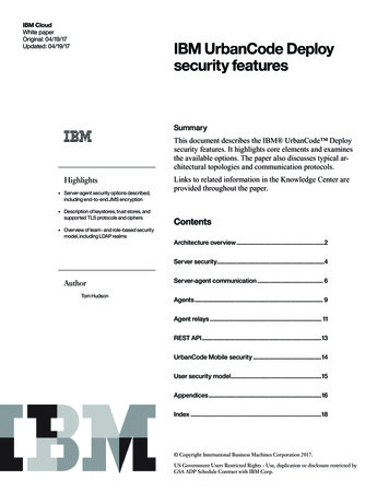
4300 Service Manual3.04300 SYSTEM(S) EXPLANATIONSMICROCONTROLLER PRINTED CIRCUIT BOARDLED Display8 bit Latch for capturingof address dataPROM: Holds all programinformation8x8 SRAM used to storecurrent spin informationDecoder for Encoderinput7 Segment LED Driver usedto drive all LED displays 5volt regulator (Digital)Fuse .5amp 250VACMicrocontroller: Controls allWeight amount and weightposition calculations and theaddressing of calibrationfactors. 5volt regulator (analog)-5volt regulator(analog)Right Offset AdjustmentAudio Transducer: Used toindicate completion offunctionLeft Offset adjustmentRight Gain ControlLeft Gain ControlEEPROM Used for storingcalibration factorsFirst stage filter ampfor transducer signal.1 to 4 signal amp fortransducer signal.10 to 4 Encoder Used forkeyboard inputFgure 1J2 Keyboard Connector3.1Microcontroller PCB Functions- Receives Analog Data from Crystal pickups, determining weight amount calculations.- Receives Digital data from Encoder System for determining weight position and shaft rotation speed.Processes Analog and Digital Data through summing circuits.- Stores input data in Ram and challenges calibration factors stored in EEPROM.- Receives keyboard input and accesses ROM for program routine.- Provides output through the LED readout, color position LEDs and piezo speaker.- Provides diagnostic codes and readings stored in ROM.- Allows manual calibration of the gain and offset adjustments for the pickup amplifier.- Regulates voltage and provides fused protection for all digital circuits.- Controls the motor rotation and braking functions.3.2Encoder- Phase 1 and 2 are responsible for locating the position of theimbalance.- Home reference is used to sense shaft movement andprovide this input to the Microcontroller.- Stabilizer arm is used to ensure the encoder does not rotate.- Uses 100 windows which is multiplied 4 times by the computerto give a reading of 400 (0 to 399) or a resolution of .9 degrees.Figure 25
4300 Service Manual3.3 Brake system: Used to stop the tire's rotationduring any part of it's spin cycle. The Brake systemis an electric-magnetic induction system using themotor a bridge rectifier and some control electronics.When a stop command or a brake command isentered by the computer, a DC voltage is generatedby the bridge rectifier. This DC current is thenlimited by a braking resistor, routed through a relayand applied to the motor. An AC motor when fedwith DC current will tend to "Buck" any rotation.This bucking will stop the rotation of the shaft. Shaftrotation is sensed by the encoder circuit, as the shaftstops the computer disconnects the DC brake. ThisDC brake is also used for the "Sticky-at-Top" feature.Bearingsassembly.3.5 Transducers: Are used to provide imbalanceinformation to the Microcontroller. The input information is a voltage which varies in amplitude depending on the amount of force being applied.The Microcontroller will begin calculating weight amountreadings once the proper transducer input is provided.The transducers sense theamount of force being appliedwhile spinning. This information of a repetitive staticimbalance coupled with the Transducer locationshaft speed information beFigure 5ing provided by the encoder will provide the necessary information needed by the computer to calculatethe weight imbalance as well as the imbalance position.ShaftPCBFigure 43.4 Shaft and Bearings: Are designed to operatein a noise free environment. The shaft is balanced towithin 0.03 ounces at the time of manufacturing. Thebearings are Ball bearings which are shielded notsealed. Sealed bearings induce noise in the systemand would not allow the bearings to operate smoothly.A grease coating is applied to the bearings, shaft andbearing housing to help eliminate noises which couldinterfere with the operation of the balancer.Locktite should not be used to hold the bearings inplace.The shaft and bearings are available only as anTransducerinputShaftFigure 66
4300 Service Manual3.6 Touch panel: Used for the entry of all commands to the microcontroller. It consists of a metalplate for the mounting of the printed circuit board anda vinyl overlay with an eleven conductor ribboncable. Twisting or crimping the ribbon cable willdamage the conductors. Striking the touch panelwith anything other than a finger may damage it.Clean the touch panel with a dampened cloth of mildammonia or use a lanolin based hand cleaner withoutgrit. Don't use harsh chemicals to clean the touchpanel.Figure 74.0Spin cycle explanation4300 BalancerSpin cycle explanation140 RPMEncoder senses stablespeedMotor Accelerateswheel toproperRPMEncoder & transducerinput becomes stable.Computer looks forequal transducer output during 2 rotations.Position and weightreadings are taken for10 rotations. LOC 1-8is displayed.Brake circuit is applied. Shaftstops.0 RPM0 RPMWeight amount displayed indicates endof spin cycleTime7
4300 Service Manual4300 Self diagnostic "F" Codes5.0The 4300 incorporates self diagnostics to assist the user and technician in troubleshooting, calibration and repair. Refer to the following for explanations of each available code.5.1F0 - RE-CALCULATE AND DISPLAY WEIGHT AMOUNT FROM LAST SPIN.Data from the last spin in current memory is used with any new parameters or set-ups todisplay new weight amounts. Current memory is maintained until the next spin cycle or until the unitis turned off.5.2F1 - BALANCER CALIBRATION(BASIC END-USER CALIBRATION)Press “F1 and ENTER”A: If EEPROM has not been initialized (this is the first time the board has been calibrated),then the balancer will first ask for calibration of the distance gauge as follows:123456Placedistancegauge here“CAL DIS” will be displayed.Press “ENTER”.Initialization calibration distance value (140) will be displayed.Measure to left face of the bell flange with the distance gauge.Enter this number via the keyboard.Perform steps B.1 through B.7.B: If EEPROM had already been initialized, then the balancer will godirectly to this procedure to set calibration factor for span and encoder(end user calibration):Figure 81 “CAL SLU” and "ROT 360" will be displayed alternately.2 Install calibration slug onto left face of bell adapter. Rotate the bell atleast one full revolution3 Press "ENTER", Place the calibration slug at the 6 o’clock or bottomdead center (BDC) position. Press “ENTER”. “SPN SPN” will bedisplayed as the shaft spins.4 Unit will display “CAL —-” during readings, brake, and then display“SLU OFF”.5 Remove calibration slug.6 Press enter. "SPN SPN” is displayed during spin cycle.7 Unit will brake, then display “CAL G”.Unit is now calibrated.5.3Cal Slug at"BDC" Figure 9F2 - ROUND-OFF MODE (WEIGHT AMOUNT DISPLAY)Weight amounts are rounded off to the nearest 0.25 ounce (5 gram) increment. Imbalances of 0.30 ounces or less (8.5 gramsor less) will round to zero. This is the turn-on (or default) mode.5.4F3 - NON-ROUND-OFF MODE (WEIGHT AMOUNT DISPLAY)Weight amounts are displayed in 0.05 ounce (1 gram) increments. This setting is in volatile memory, and reverts to “F2”when the unit is turned on.8
4300 Service Manual5.5F4 - OUNCES MODESets weight amount display to ounces. This setting is in non-volatile memory. When the balancer is turned off and on, this modeof operation will be maintained.5.6F5 - GRAMS MODESets weight amount display to grams. This setting is in non-volatile memory. When the balancer is turned off and on, this modeof operation will be maintained.5.7F7 - CONVERT WHEEL DIAMETER TO MILLIMETERS MODEAllows direct entry of metric wheel diameters (i.e. 390 mm) when balancing this type of wheel. Selecting F7 toggles between“CON ON” (dia in mm) and “CON OFF” (dia in inches).Press any key to exit this set-up.This setting is in volatile memory. When the balancer is turned off and back on, the setting reverts to “CON OFF” (dia in inches).5.8F8 - WEIGHT PLACEMENT ANGLE SIZE SELECTION MODEThe entry of this code causes the green light to be displayed for either one encoder count or two Selecting “F8” toggles betweenthe following modes:1 .When the “FIN ON” message is displayed, the balancer will then be in the fine angle resolution mode (narrowwindow).The resolution for the wheel weight position display is set at 0.90 degrees (one encoder count).2. When the “FIN OFF” message is displayed, the balancer will then be in the wide angle resolution mode(wide window). The resolution for the wheel weight position display is set at 1.80 degrees (two encoder counts).This display mode entry will be recorded in non-volatile memory. When the balancer is turned off and on, this mode of operationwill be maintained. The recommended mode is the FIN OFF for the majority of users.5.10“CAL DIS” will be displayed.Press “ENTER” and the old factor will be displayed. Place the distancegauge against the left face of the Shaft Adapter (bell). Read the distancegauge, and enter the new reading into the computer through thekeyboard. The computer will automatically exit this routine when thelast digit has been entered.This data entry will be recorded in non-volatile memory.Even though the balancer is turned off and on, this information will bemaintained.5.11READ NEWVALUES HEREF12 - CALIBRATE DISTANCE GAUGEíç PLACE GAUGE TIPHEREF20 - DISPLAY SHAFT IMBALANCEThe entry of this code causes the computer to display the shaft imbalance value which was recorded in non-volatile memory duringthe last shaft imbalance diagnostic procedure (F21). For this information to be meaningful, the following parameters must beentered: (DIST 62, WIDTH 5.5, DIA 13.0)This information will remain the same until the F21 diagnostic procedure is run again.5.13F30 - TEST THE DISPLAYThe entry of this code causes the computer to turn on all 7 segments of each display block for 2 seconds.Allows you to verify that all 7 segments of each LED is functioning. (All 7 segment displays show 8’s).All characters will begin to scroll across the display in sequence.This test also verifies the computer understands input commands and has the ability to provide correct output.Press “CANCEL” to exit this routine.5.14F31 - TEST THE KEYBOARDThe entry of this code causes the computer to display each key as it is pressed.With “CANCEL” being the last entry to be made, you can now press each key and verify the proper response is present on thedisplay.Press “CANCEL” to exit this routine.9
4300 Service Manual5.16F42 - DISPLAY LEFT AMPLIFIER GAIN AND OFFSETThis display is used to check and calibrate the left channel amplifier gain and off set.Note: These values are only meaningful when using the standard calibration slug.Locate the left gain and offset adjustment potentiometers through the access plugs or on the microcontroller PCB. See figurebelow for POT location pictorial. The POT locations are labeled on the back side of the printed circuit board. Adjust using apotentiometer adjustment screwdriver.Calibrate gain and offset as follows;Observing readings.The left display should show a gain reading centered on 1.58 /- 0.02 (volts)Gain reading, adjust left gainpot (R7) for 1.58 /- 0.02Offset reading adjust pot (R23)for 2.50 /- 0.01Adjust left gain potentiometer until the proper readings are obtained .RIGHT OFFSETThe right display should show the value of the amplifier offset voltageLEFT OFFSETcentered on 2.50 /- 0.01 (volts) Adjust left offset potentiometer untilRIGHT GAINthe proper readings are obtained .LEFT GAINNOTE - The gain adjustment will have some effect on the offsetvoltage. Make sure both displays are within specification.Access-hole plugsPress “CANCEL” to exit this routine.5.17 F43- DISPLAY RIGHT AMPLIFIER GAINAND OFFSETThis display is used to check and calibrate the right channel amplifiergain and offsetNote: These values are only meaningful when using the standardcalibration slug.Locate the right gain and offset adjustment potentiometers through theaccess plugs or on the microcontroller PCB. See figure below for POTlocation pictorial. The POT locations are labeled on the back side of theprinted circuit board. Adjust using a potentiometer adjustment screwdriver.Gain reading, adjust right gainpot (R12) for 1.64 /- 0.02Offset reading, adjust pot (R17)for 2.50 /- 0.01Calibrate gain and offset as follows;Press enter to spin. Observing readings.The right display should show a gain reading centered on 1.64 /- 0.02 (volts)Adjust right gain potentiometer until the proper readings are obtained . See figure 1, page 5 for pot location.The right display should show the value of the amplifier offset voltage centered on 2.50 /- 0.01 (volts)Adjust right offset potentiometer until the proper readings are obtained .NOTE - The gain adjustment will have some effect on the offset voltage. Make sure both displays are within specification.Press “CANCEL” to exit this routine.10
4300 Service Manual5.18F40 - DISPLAY POWER SUPPLY VOLTAGEEnter F40 and press enter, the display will read BRD VLT, meaning board voltage. The regulator voltage delivered by the powersource to the pcb (in volts) will be shown on the display.The reading should be approximately 6.5 to 15.0 volts. Refer to the troubleshooting section of this manual for more details. Thistest is valid for whatever the AC line input voltage options.Press “CANCEL” to exit this routine.5.19F50 - DISPLAY ENCODER POSITIONNumbers between “0” and “399” will be displayed on the right display, indicating the current encoder pulse.Dashes will be displayed on the left display, indicating phase “1” (first dash), phase “2” (second dash), and home reference (thirddash) of the encoder.Press “CANCEL” to exit this routine.5.20F51 - DISPLAY TOTAL ENCODER COUNTS IN ONE REVOLUTIONDisplay should read “399” when the wheel is turning.Press “CANCEL” to exit this routine.5.21F53 - DISPLAY SHAFT SPEED IN RPMSpin the shaft and the RPM will be displayed, a reading of 140 /- 10% is normal. Press “CANCEL” to exit this routine.5.22F54 - CALIBRATE ENCODERCalibrates the encoder’s zero count.Rotate the bell adapter one complete revolution and then press “ENTER”.”ENC OFF” will be displayed.Press ”ENTER” the encoder position will be displayed.Install the calibration slug, and rotate the shaft so the slug is directly at the 6 o’clock position.Press “ENTER” to cause the computer to record the present position as the correct encoder zero position stored in non-volatilememory and exit the routine, or press “CANCEL” to exit this routine without changing the encoder calibration. F50 should bechecked after the running the F54 calibration to verify correct position.5.23F60 - DISPLAY PROGRAM REVISION LEVELLeft hand display will show “43”, and right hand display will show revision level (i.e. “2.24”).Press “CANCEL” to exit this routine.6.0OTHER SELF DIAGNOSTIC CODES6.4CAL ER : Will flash should a error occur during the calibration procedure or should the system detect a problemwhen accessing the EEPROM for its calibration factors.6.2SHT UNB: Will flash after a calibration attempt whenever the shaft is unacceptably unbalanced. First review thecalibration procedure to assure that the correct steps are being followed. It is common for this message to appear because of acalibration sequence has not been adhered to.6.3RPG/LPG LO: This is a message that appears whenever the pcb amplifier gains are set too low or whenever thereis some type of malfunction with one of the pickups. RPG stands for "Right Pickup Gain"; LPG stands for "Left Pickup Gain".11
4300 Service Manual4300 systematic troubleshootingBasic troubleshooting of the 4300: is simplified using a systematic check of the various systems. Thismanual will assume the following;1. The neccesary hand tools are available (See tool list page 19)2. A basic understanding of systems functions.3. The use of this manual in its entirety.Identify the symptomNo displayNo keyboard entryNo spin cycleNo position indicationNo weight amount displayRequires multiple spins to balance wheelVibration on vehicle after balanceNo brake functions7.0Systematic troubleshooting: is a recommended procedure for repairing the balancer. Follow thesesteps when repairing the 4300.7.1Check AC power:AC power is used to power the transformer/power supply which converts 120/220 volts AC to DCpower6.5 volts - 15 volts depending on the output of the adapter. DO NOT assume the poweroutlet is good. Verify the AC output from the wall outlet by volt meter, substitution of a knowngood AC powered device, or the use of a polarity tester.YesIs there an LED display?Press F-40. Is the readingbetween 6.5-15.0?NoInspect switch andconnections.Repair as required.NoIs 6.5- 15 volts of DC powerpresent at Conector J1 pins 6&7?YesYesDC power is OK.Replace fuse F-1.YesIs 6.5- 15 volts of DC powerpresent at plug J1.Repair wires between J6 and J1.NoReplace Microcontroller PCB ifLED display isn't present.Replace power supply assembly.12
4300 Service Manual7.2Check DC power: (Refer to the schematic Figure 20 of this manual).7.3Check computer functions: the Microcontroller self tests itself every time power is cycled. If theCPU has found a problem in any of its address, data, or control circuits it will cease proccessing functionsand the sonic beeper will begin to sound. A stuck key on the touch panel would also cause this symptom.An easy way to test the microcontroller is to run test F-30.YesAre all characters being displayed during test F-30?Microcontroller processingcircuits are OK.NoProcede to testing the touchpanelTesting the touch panel (Refer to figure 21)YesCan you enter the command F-31and do all the keys respond?NoJumper pins 4 & 11 of the J2connector (power off).Touch panel is OK.Yes(power on) Is there a display of"6.13" on the display?Replace Microcontroller PCB.Replace Touchpanel.7.4Spin cycle test:NoNoNoWill " SPN" display whenENTER button is pressed?Replace microcontroller PCB.Go to weight amount test (7.5).Spin cycle is functioning correctly.Is "SPN" display when the shaftis rotated?YesNoYesWith tire mounted will balancerdisplay "--- ---" while being spunup to speed by hand?Go to weight postion test (7.5).when the wheelYes Is "SPN"hasdisplayedstopped rotating?YesYesDoes the balancer display"--- ---"constantly while being spun up tospeed?YesNoNoAre weight amounts displayedwhen the wheel has stoppedrotating?13
4300 Service Manual7.5Weight position test: Before beginning the following tests; mount a calibration slug on the backside of the shaft adapter. Turn the balancer on and spin the shaft using the "location 7" balancing mode.NoAre all the position LEDs Lit?NoReplace Microcontroller PCB.NoNoYesYesYesIs the left green LED on with thecalibration slug at 6 o'clock.YesPerform F-54 encoder calibration.Perform F-50. Is the display reading"000 ---" with the cal-slug at 6o'clock?Perform F-51. Does the displayread a number other than "399"when the shaft is rotated 1 fullturn?YesYesWeight position is OK.Repair the encoder mounting or setscrew. If these are not loosereplace the encoder.Measure for 4 to 5 volts at J1 pin5. Is it there?Measure J1 pins 2,3,4 withO'scope set at 5volts/div and20ms/div. While rotating the shaftlook for a 5 volt DC square wave.Is it there?Replace microcontroller PCB.YesNoReplace Microcontroller PCB.NoMeasure J5 pins 1,3,4 usingO'scope as descibed in last step.Are signals present?Repair wiring harness betweenencoder and J1 connector. 6.6-15 VDCNoReplace encoder.J33 To: 110381pcb14.5 voltsFigure 1014
4300 Service Manual7.6Weight amount test: Before beginning the following tests; mount a calibration slug on the balanceradapter plate. Turn the balancer on. Insure the balancer is in the Location 1 balancing mode except whereindicated by flow chart. Any repairs or mechanical calibrations will require complete "End User" calibration(F-1) before returning the 4300 to operation.Perform F-1 calibration.Does the 4300 calibrate?YesInstall Cal slugNoSpin the balancer. Does it readread 5.50 Ozs. (155g) in the leftwindow? (location 7)(F2mode)YesTorque the transducers to 30 inchpounds.YesNoLooking at the left window duringF-42 or F-43. Does the gainincrease when the balancer isspun?Perform F-42 and F-43 calibraton.(Refer to "F" codes for calibration)Will it calibrate?YesNoRemove calibration slugPress "F3 enter"Weight amount is working correctly.Refer to symptom charts for otherweight amount problems.When the balancer is spun, is theleft window display more than 0.10during F-42,43?YesReplace left or right transducer asapplicable. Calibrate and retest.Weight amount is working correctly.Refer to Symptom troubleshootingfor other weight amount problems.8.0NoNoRefer to Symptom troubleshootingprocedures(8.1Weight Chasing).Symptom troubleshootingSymptom troubleshooting assumes all systematic troubleshooting techniques have been used and that thevarious systems in the balancer are in working order.8.1Additional weight needed to balance tire. (Weight Chasing)Static weight chase.Using a balanced wheel assembly, enter the tire's parameters.Place the cal slug on the balancer and using location 7, spin the balancer.If the balancer reads other than 5.50 ounces, check the following;1.Shaft imbalance (F-20)2.Bell housing runout. (see 8.2 and 8.3)3.Transducer gain and offset (F-42, F-43)15
4300 Service ManualDynamic weight chaseRemove the calibration slug.Using "location 1"add a 3 ounce test weight to the inside plane of the wheel.Spin the balancer. If the balancer reads other than 3 ounces check the following;1. Bell housing runout.2. Transducer gain and offset.3. Mounting adapters4. Transducer linearity. (the ability of the transducer to produce consistent output)5. Distance gauge calibration or physical damage to the distance gauge.If a reading of 3 ounces is obtained , move the weight to the outside plane. If the weight reads other than3 ounces check the following;1. Bell housing runout.2. Transducer gain and offset.3. Mounting adapters4. Transducer linearity. (the ability of the transducer to produce consistent output)5. Distance gauge calibration or physical damage to gauge.Figure 12Runout should be measured when the balancer requires more than one weight per tireside to balance the wheel.Bell housing runout not to exceed0.002 of an inch.8.3Measuring Bell face runout16
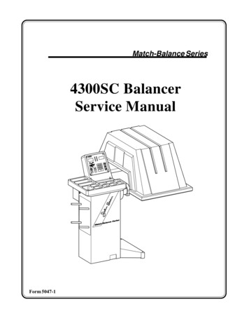
4300 Service Manual8.4Transducer Output: UsingLocation mode 7 and F-42 for the lefttransducer and right transducer, checkthe transducer linear output in the following manner;Use a balanced wheel5oz4oz.3oz.1) Spin the balancer until the greenLED position indicator is lit.Output should be 0.00 to 0.10 with abalanced wheel.2) Add a one ounce weight to the insideplane. Refer to the chart and then to thereading.2oz.1oz.0 oz.X 010020 030 040 050Gain displayed in left windowDetermine transducer linear output3) Continue to add weight using only1 weight in the same wheel position.Readings should be very close /- 0.10to those values shown on the chart.5oz4) Remove the right and left transducerconnections from the main PCB.Connect the right transducer plug to theleft transducer connector on the MainPCB.Perform the steps 1 to 3.Again the readings should compare tothe chart. Numeric values may be varybut linear output should remain constant.4oz.3oz.2oz.1oz.0 oz.X 010 020 030 040 050Gain displayed in left window right transducer.If the transducer will not give a linearoutput replace it. Torque the new transducer in place and re-test.5oz5) Be sure to calibrate (F-1) the balancer when you have completed thisprocedure.3oz.4oz.2oz.Use the blank chart to record your actual 1oz.readings for the left and right transduc0 oz.ers.X 010 020 030 040 050Gain displayed in left window for left transducer.17
4300 Service Manual8.5Tire vibration after the balance: Generally speaking this condition will occur in a wheelthroughout all speed ranges if the balancer is not working properly.If the condition only exists during given speed range look for:Tire runout (radial and axial),Bent rimsWheels which are not hub centric. (Rims that are not centered by the center hole) and require the useof an optional mounting method.Damaged bearing races or bent axles.If the balancer has passed all systematic troubleshooting procedures and it appears to be functioningcorrectly, check the following:1. Follow the procedures given for the F-20 and F-21 (shaft imbalance test)2. Check cones for play when mounted to the shaft.Cone tolerance is .003 inches of up and down movement on the shaft.3. Check the encoder's Phase 1 and Phase 2 signal to ensure they are at 90 degrees to each other.(See figure 2 and troubleshooting guide for weight position)4. Check the torque of the suspension system bolts.If these suggestions do not solve your problem.RememberFMC is striving to be OUR CUSTOMERS MOST VALUED EQUIPMENT SUPPLIER.If you require additional assistance;Phone our technical assistance desk at:1-800 FMC-TEAM inside the continental United States or1 - (501) 327-4433 for all overseas customers.Our FAX number is (501)-450-1585Please direct all technical questions to the attention of technical assistance.18
4300 Service Manual9.0Tools required to service the 4300Tools Required to service the 4300WrenchesOther Tools5/16" or 8mm wrench or nut driver1/2" or 13mm Wrench9/16" or 14mm wrench5/8" wrench3/4" or 17mm wrenchInch pound torque wrenchFoot pound torque wrench6 inch in1/16" increments or 50mm ruler#2 Phillips or cross tip screwdriverDigital volt / ohm meterPotentiometer adjustment screwdriverAllen Wrenches1/8" Allen wrench5/32" Allen wrench3/16" Allen wrench5/16" or 8mm Allen wrench12mm Allen wrenchSuppliesLoctite #222 and #609Silicone based grease (NAPA Balkamp #765-1351)Putty for fine wheel balancing.**A tire/wheel balanced to within 0.10 oz (1gr.) on the inside and outside or 0.20 oz.statically is required for the troubleshooting procedures.19
4300 Service Manual10.0Disassembly of the 4300(1) Remove 4 screws(2) Remove 4 screws(3) Remove cover(*) wiring connections to PCB.10.1 Remove the weight trayand Microcontroller PCBRemove the top cover of the 4300 byremoving the Touchpanel first. Be careful when pulling the panel back andwatch for the wires which are attachedto the PCB.(*)Disconnect the wires by gently raisingthe connector clip and pulling back onthe wire's socket. DO NOT PULL ONTHE WIRES OR ATTEMPT PULLING UP ON THE CONNECTOR.Squeeze the touchpanel's connector sideclips and gently pull back to disconnectthe flat ribbon cable.Refer to the drawing and remove theupper cover in the numbered order.Assembly is the reverse order.Figure 1310.2 Removing the EncoderRefer to the drawing and remove the encoder in the numberedorder. Assembly is the reverse of disassembly. Care should betaken to insure the encoder's slotted shaft is correctly inserted inthe shaft opening. The encoder should not wobble when the shaftis turned.Once installation of the encoder is complete and power is restoredto the balancer, you will need to refer to the Encoder calibrationsection of this manual to complete the installation procedure.Follow the numbered sequence in the drawing for removal of thetra
4300 Service Manual 3.3 Brake system: Used to stop the tire's rotation during any part of it's spin cycle. The Brake system is an electric-magnetic induction system using the motor a bridge rectifier and some control electronics. When a stop command or a brake command is entered by the computer