Transcription
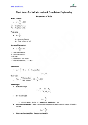
www.gradeup.coShort Notes for Soil Mechanics & Foundation EngineeringProperties of SoilsWater contentW w W 100WSWW Weight of powerWS Weight of solidsVoid ratio e VvVsVv Volume of voidsV Total volume of soilDegree of SaturationV S w 100VvVw Volume of waterVv Volume of voids0 S 100for perfectly dry soil : S Ofor Fully saturated soil : S 100%Air Content ac Va 1 s Va Volume of airVvSr ac 1% Air Void %na VVolume of air 100 a 100Total volumeVUnit Weight Bulk unit weight Ws WwW V Vs Vw VaDry Unit Weight d o Dry unit weight is used as a measure of denseness of soilSaturated unit weight: It is the ratio of total weight of fully saturated soil sample to its totalvolume. sat WsVWsatVSubmerged unit weight or Buoyant unit weight1
www.gradeup.co ' sat w sat unit wt. of saturated soil unit wt. of water Unit wt. of solids: s WsVsSpecific GravityTrue/Absolute Special Gravity, G Specific gravity of soil solids (G) is the ratio of the weight of a given volume of solids to theweight of an equivalent volume of water at 4 .G Ws sVs . w wApparent or mass specific gravity (Gm):Gm where, is bulk unit wt. of soil sat for saturated soil mass d for dry soil massGm G or d or satW V . w wRelative density (ID) To compare degree of denseness of two soils.1Compressibilitye e% I D max 100emax emin11 d% I D d min 10011 d min d maxI D Shear strength Relative Compaction Indicate: Degree of denseness of cohesive cohesionless soilRc D DmaxRelative Density Indicate: Degree of denseness of natural cohesionless soilSome Important Relationships Relation between d , d (ii) Vs 1 wVW(iii) Ws 1 e1 w2
www.gradeup.co Relation between e and nn e1 eore n1 n Relation between e, w, G and S: Se w. GBulk unit weight ( ) in terms of G, e, w and w , G, e, Sr, w (G eS r ) w1 eG (1 w) w{Srxe wG}(1 e)Saturated unit weight ( sat.) in terms of G, e & w . wSr 1 sat 1 e Dry unit weight ( d ) in terms of G, e and w G wG w(1 a )G w 1 e 1 wG1 wGSSubmerged unit weight ( ') in terms of G, e and w G e Sr 0 d G 1 sat w ' . w 1 e Relation between degree of saturation (s) w and GS W w1(1 W ) GCalibration of Hydrometer Effective depth is calculated as1 VH e H1 h H2 Aj where, H1 distance (cm) between any hydrometer reading and neck.h length of hydrometer bulbVH volume of hydrometer bulb3
www.gradeup.coPlasticity Index (Ip): It is the range of moisture content over which a soil exhibits plasticity.Ip WL - WpWL water content at LLWp water content at PLIp (%)01 to 55 to 1010 to 2020 to 40 40Soil DescriptionNon plasticSlight plasticLow plasticMedium plasticHighly plasticVery highly plasticRelative Consistency or Consistency – index (Ic):W WNIC LIp For WN WL I C 0 For WN WP I C 1 Liquidity Index (IL)IL WN WPIPFor a soil in plastic state IL varies from 0 to quidVery softsoftmediumstiffstiffVery stiffOR HardHard ORvery hardIC 00-0.250.25-0.50.50-0.750.75-1.00IL 10.75-1.000.50-0.750.25-0.500.0-0.25 1 0 1 0Flow Index (If)If W1 W2log10( N 2 / N1 )Toughness Index (It)IT For most of the soils: 0 IT 34IPIF
www.gradeup.co When IT 1, the soil is friable (easily crushed) at the plastic limit.Shrinkage Ratio (SR)V1 V2 100VdSR w1 w2V1 Volume of soil mass at water content w1%.V2 volume of soil mass at water content w2%.Vd volume of dry soil mass V1 Vd 100 Vd SR (W1 Ws )If w1 & w2 are expressed as ratio,SR PropertiesPlasticityBetterFoundationMaterial uponRemouldingCompressibilityRate of loss inshear strengthwith increase inwater contentStrength ofPlastic LimitRelationship (V1 V2 ) / Vd(V V ) / wBut , w1 w2 1 2W1 W2WsW 1 SR s . dVd w wGoverningParametersPlasticity IndexConsistencyIndex Liquid LimitFlow Index ToughnessIndexCompaction of SoilOptimum moisture content( d ) max imum ( d ) max imum Maximum dry density Density of soilwoptimum Optimum moisture content5 1 woptimum
www.gradeup.coComparison of Standard & Modified Proctor TestInference G wfor, rd max' S 1, ha 0 correspond to 100% saturation or zero air void line.wG1 S(a na )G w d 1 wG d Ratio of total energy given in heavy compaction test to that given in light compaction test 4.9 g (5 25) 450 4.52.6 g (3 25) 310Compaction Equipments1.Type ofEquipmentSuitabilityfor soil typeNature ofprojectRammers orTampersAll soilsIn confinedareas such asfills behindretainingwalls,basementwalls etc.Trench tictyred rollers3.Crushedrocks,gravelssandsSand,gravels silts,clayey soilsBase, subbase andembankmentcompactionfor highways,air fields etc.Earth dams.Core of earthdams.Clayey soilsEmbankmentfor oil storagetanks etc.6
www.gradeup.co4.Sheep footRollersSandsVibratoryRollers5.Compaction TestsStandard proctor testModified proctor test(Light compactiontest)(Heavy compactiontest) Volume of mould942ccNo. of layers -3No. of blows perlayer - 25Height of free fall 304.8 mm (12inches)Wt. of hammer 2.495 kg (5.5 /b) Volume of mould942 ccNo. of layers -5No. of blows perlayer -25Height of free fall 457.2 mm (18inches)Wt. of hammer 4.54 kg (10 /b)Indian standard lightcompactionIndian standard heavycompactionV – Volume of mould1000 cc Volume of mould1000 ccH – Height of free fall310 mm Height of free fall450 mmW – Wt. of hammer2.6 kg Wt. of hammer 4.9kgN – No. of layers 3 No. of layers 5N – Blows per layer 25 Blows per layer 25Stress Distribution in The SoilBoussinesq's TheoryVertical stress at point 'P'. ( Z )7
www.gradeup.co 3Q 1 Z 2 z 2 r 21 z 2 Z kB .5/2 where, Q Point load in newton Qz25/2 3 1 kB 2 r 2 1 2 z 3kB max 0.47752 ' Z ' below the point load at depth z, z 0.4775.QZ2Westergaard's Theory Q 1 z 2 z 2r 21 2 zQ z kW .Z2kw max 0.3183 3/2Boussinesq's Result z max 0.0888Qr2 z max 0.1332Q222Westergaard's Results Vertical Stresss due to Live Loads 2q ' 1 z z X21 2 z8 2
www.gradeup.cowhere, z Vertical stress of any point having coordinate (x, z) Vertical Stress due to Strip Loading z where, z Vertical stress at point 'p' Z q 2q Xsin 2 B2 [ sin ]Vertical stress below uniform load acting on a circular area. Z q(1 cos3 )where, cos zr z22Newmark's Chart Method Influence of each area 1 0.005Total no. of sectoral area Z 0.005qN A where, NA Total number of sectorial area of Newmark's chart.Equivalent Load Method Z Z1 Z2 Z3 . where, Z1 k B1Q1z2 Z k B2 .2Q22.z2Trapezoidal Method q ( B L)( B 2 z )( L 2 z )q ( B L) z ( B 2 z )( L 2 z )q ( B L) z ( B 4 z )( L 4 z ) z at depth ' z ' Shear Strength of SoilShear Strength9
www.gradeup.co c 4 max imum2where, max. Angle between resultant stress and normal stress oncritical plane. Friction angle of soil c 4 2 for clay 0 c 4 tan (iii) C tan , for C- soil. C , for C-soil (clays). 1 3 tan 2 (45 ) 2C tan(45 ),2 1 3 tan 2 (45 ) , for -soil. 1 2C , for C-soil.2 for C- soil.2Mohr Coulomb's Theory s C ' n tan ' C' Effective cohesion n Effective normal stressand ' Effective friction angleDrained conditionEffective stressanalysis and postconstruction stabilityis checked.Undrainedcondition withpositive pole waterpressureTotal stress analysisand stability should bechecked immediatelyafter construction.Undrainedcondition withEffective stressanalysis and long term10
www.gradeup.conegative porewater pressurestability should bechecked.Direct Shear Test s C ' n tan ' Results of Direct Shear Test 1 3 d ( d ) failure ( 1 3 ) failure S C n tan 3 Cell pressure or all-round confining pressure d Deviator stress A Area of failureA (1 v )A 0where, A0 Area of beginning(1 L ) PA v Volumetric strain v 0 forU U testwhere, V Volume of water escaped out v V 4 VforC DtestVD 2 L Initial Volume Axial strainUnconfined Compression Test qu ( 1 ) f where, qu unconfined compressive strength.Here, 3 0 ( 1 ) f 2C tan 45 , forC soil2 ( 1 ) f 2C, forC soil.q S C u , for clay's or c-soil.211
www.gradeup.co For clays as sand/coarse grained soil/can't sland in equipment with no lateral pressure.Used to rapidly assess clay consistency in field.To get sensitivity values of clay.Vane Shear TestLab SizeField SizeHeight ofvane (H)20 mm10 to 20 cmDia of vane(D)12 mm5 to 10 cmThickness ofvane (t)0.5 to 0.1 mm2 to 3 cmShear StrengthS T H D D2 2 6 When top and bottom of vanes both take part in shearing. S T H D D2 2 12 When only bottom of vanes take part in shearing. St (qu )undisturbed(qu )remoldedwhere sf SensitivityPore Pressure Parameter U c U cB c 3 ooo0 B 1B 0, for dry soil.B 1, for saturated soil.A A.B where A Pore pressure parameter U d A d U d Change in pore pressure due to deviator stress. d Change in deviator stress U Change in pore pressure12
www.gradeup.co U U c U d U B[ 3 A( 1 3 )]Deep FoundationBearing capacity of piles Analytical MethodQup Qeb QsfQup qb Ab qs AsQup Ultimate load on pileQeb End bearing capacityQsf Skin frictionqb End bearing resistance of unit area.qs Skin friction resistance of unit area.Ab Braking areaAs Surface area qb qS C , Adhesion factor C Ca Unit adhesion between pile and soil. C Average Cohesion over depth of pile.QQsafe up where, Fs Factor of safety.FsQQQsafe eb sfF1F2 9C ,C Unit Cohesion at base of pile for claysDynamic Approach Engineering News Records FormulaWHS CQWHQap up 6(S C )Qup Qup Ultimate load on pileQap Allowable load on pileW Weight of hammer in kg.H Height of fall of hammer in cm.S Final set (Average penetration of pile per blow of hammer for last five blows in cm)C Constant 2.5 cm for drop hammer 0.25 cm for steam hammer (single acting or double acting) Hiley Formula (I.S. Formula)Qap h . b .WHS 13C2
www.gradeup.coQap QupFsFs Factor of safety 3 h Efficiency of hammer b Efficiency of blow. h 0.75to0.85 for single acting steam hammer h 0.75to0.80 for double acting steam hammer h 1 for drop hammer.Energy of hammer after impact b Energy of hammer just before impactW e2 P b when w e.pW P2 W e2 P W e2 P b . when w e.p W P W P w Weight of hammer in kg.p Weight of pile pile cape Coefficient of restitutions 0.25 for wooden pile and cast iron hammer 0.4 for concrete pile and cast iron hammer 0.55 for steel piles and cast iron hammerS Final set or penetrations per blowC Total elastic compression of pile, pile cap and soilH Height of fall of hammer.Under-Reamed PileAn 'under-reamed' pile is one with an enlarged base or a bulb; As1 bL1 qs1 CAs2 bu L2 qs2 C 1. 1.Qup qb Ab qs1 As1 qs2 As214
www.gradeup.co For Cohesive soilQnf Perimeter.L1 C for Cohesive soil.Qnf Total negative skin frictionsFs Qup QnfApplied loadwhere, Fs Factor of safety.For cohesion less soils1Qnf P x force per unit surface length of pile P K Dn2 .tan 21Qnf PDn2 K .tan . (friction force μH)2where unit weight of soil.Group Action of Pile Group Efficiency ( g ) g Qugn.QupoFor sandy soil g 1oooFor clay soil g 1 and g 1Minimum number of pile for group 3.Qug qb Ab qs As where qb 9C for clays A B2 qs C A 4 B.Ls boFor Square Group Qug .Qup Qug Sr When Piles are Embended on a Uniform ClayQugFOSSgwhere, Qug Allowable load on pile group.SiS g H Cc H 0log10 0 and1 e0 0 Q 0 ( B z )2In case of SandSr Sg2 4 B 2.7 where, B Size of pile group in meter.Si B 3.6 15
www.gradeup.coSheet Pile WallsSheet Pile Walls Embedded in Sands d(H d ) Pa33 without factor of safety.Pp d(H d ) Pa . with factor of safety.Fos 3311Pp k p d 2Pp k p ( H d ) 222Pp .Sheet Pile Walls Embedded in Clays Active earth pressure at depth H.Pp q 2C Passive earth pressure at depth 'H'.Pp 2C Resultant earth pressure of depth H. is(Pp – Pa)Pp Pa 4c q Resultant earth pressure at base i.e. at depth (H d) is (Pp – Pa)Pp Pa (4c q) Resultant earth pressure of base i.e. of depth (H d) is (Pp – Pa)Pp Pa (4c q)Shallow Foundation & Bearing CapacityBearing Capacity16
www.gradeup.co The load carrying capacity of foundation soil or rock which enables it to bear and transmitloads from a structure.Gross Pressure Intensity It is the total pressure at the base of the footing due to the weight of the super structure,self weight of the footing and weight of the earth fill.Net safe bearing capacityq qns nu where qns Net safe bearing capacityFsFs Factor of safetySafe bearing capacityqs qns where, qs Safe bearing capacity.Method to determine bearing capacity Rankines Method ( - soil) 2qu D f tan 4 45 2 or q D 1 sin uf 1 sin Bells Theory (C - ) qu CNc D f Nq where, Nc and Nq are bearing capacity factors.Fellinious Method: (C-soil)qult W .I r CRb.I 0qult 5.5CPrandtl Method: (C - )1qu CN c D f N q BN For strip footing2For C-soil N c 5.14, Nq 1, N 0Terzaghi Method (C - ) For strip footing1qu CN c D f N q BN 2 For square footing For rectangular footingqu 1.3CNc Df Nq 0.4 BN quD f NqBCNCL10.2B1BN2L1 0.317
www.gradeup.co For circular footingqu 1.3CNc Df Nq 0.3 DN Skemptons Method (c-soil)qnu CN c IfDfB 0i.e. of the surface.Then NC 5 For strip footingNC 6.0 For square and circular footing.where Df Depth of fo
Short Notes for Soil Mechanics & Foundation Engineering Properties of Soils Water content W 100 S W w W W W Weight of power W S Weight of solids Void ratio v s V e V V v Volume of voids V Total volume of soil Degree of Saturation w 100 v V S V V w Volume of water V v Volume of voids 0 S 100 for perfectly dry soil : S O for Fully saturated soil : S 100% .
