Transcription
Computer Aided Design of Aircraft SeatsRicardo Jorge Martins MesquitaInstituto Superior TécnicoLisboa, Portugal, November 2013ricardo.mesquita@ist.utl.ptAbstractIn the present work we studied the modeling and computer simulation of the structure of anairplane seat very similar to the structure used in the current economy class seats. The majorobjective of this study was to acquire sensitivity to the results of Static and Dynamic Simulationby certification specifications of European Aviation Legislation in use (Amend.9 CS - 25),through the development and interpretation of computer simulations.The revision in terms of existing legislation reveals great interest of itself, given the lack oforganized information, serving those that wanting to develop a product or service in the aviationindustry.The procedures performed and subsequent results obtained in the context of this thesis servesto prepare the necessary basis for the future development of a new structure for aircraft seatsthrough computational methods, as well as a preview of the results of the respective physicalcertification.By the computer simulations performed could perceive the dynamics of a type crash test whenapplied to the structure in question, obtaining locate potential areas of weakness of the structureand discriminate those that entering in plastic deformation.KEY - WORDS: Aeronautical Legislation, Simulation for Certification, CAD, Aircraft SeatsWith this thought and making use of thepotential of the software available today it ispossible to develop an almost virtualprototyping. In parallel with the developmentprocess of the CAD model are held everycomputer simulations that are necessary toestablish the future performance of the productin the real world.1. IntroductionCurrently the industry is going through a phaseof its most troubled history, with globalizationhave opened up new horizons for thedevelopment and sale of new products, butequally increased competition betweencompanies around the world. Into account thisfact with development centers should stand inmind that throughout the development of anew product the success factor is to reconcilethe best possible way the trinomial time - cost quality, by other words do well and quickly andbe the first.Thus when developing the first physicalprototype adjustments needed to launch inproduction the final product are very few, thusreducing the costs involved in the process andlead time .1
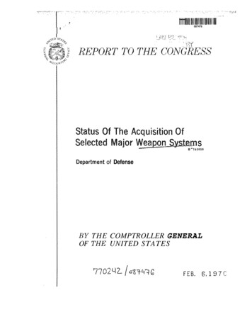
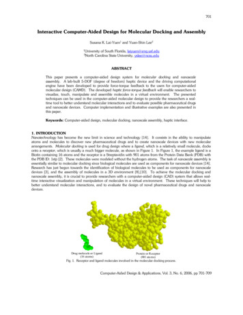
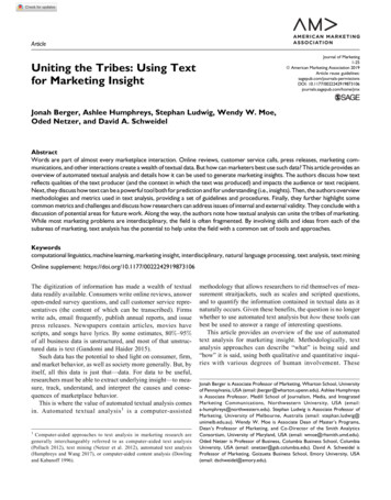
The theme of this work enters in the aeronauticworld, with the attempt to develop an aircraftseat. However, before developing a new seatconcept is essential understand how thecurrent works and its weaknesses. Over theCAD reproduction of the seat became clear thedifficulty and delay modeling, also showedsome difficulty in the acquisition of sensitivity inthe simulation of the structure.Given the difficulty felt in the perception of allthese concepts we chose to create a flowchart,which are outlined in the needs that an entityneed to possess or to obtain certification in aparticular article and approval to proceed tothe installation an aircraft.Through the cooperation between IST andTAP- SA, was possible to access a real modelof an aircraft seat used in the past by theairline, to make the dismantling and play realscale their structural key components usingCAD software. After playback, the assembly ofthe model was validated, and then developedseveral simulations with an finite elementsoftware, which aimed to test whether themodel in question was in accordance with therequirements of Aeronautical Certificationcurrently in effect (CS-25 Amendt.9).2. Introduction to LegislationFigure 2-1 Flowchart of the Certification ProcessIn all sectors of services and products, to letyou know what is expected and feel safe, thatniche needs to respond to standards andfollow certain protocols. With the globalizationthe aviation has become a key for the carriageof goods or passengers. The world hasbecome smaller and in recent years has beentowards an escalation in air traffic and isexpected to increase the capacity air available.Although it was stated as a means of transportsafer, but taking into account the inherentdangers associated with this mode oftransportation was expected introducinglegislation that serves as a ruler and square ofthe principles governing the design and use ofaircraft.In the European Certification Specifications(CS - Certification Specification) published bythe Agency match the technical standards arenot binding, which however, compliance withthese is a necessary condition for obtainingcertification. [1]As regulations change over time, sometimesdue to the detection of problems orsuggestions for improvements, it should benoted that not all aircraft are in service complywith the design regulations for the year due.The regulations are revised and released asan Amendment (Amendment Number).In paragraph 25.561 of EASA CS-25 arestipulated instructions of static loading tests.They argue that the respective chairs andfittings shall not deform significantly before theapplication of the following inertial forcesacting independently of the surroundingstructure: [2]At the level of European airspace the entityresponsible for aviation is the EuropeanAgency for Aviation Safety Agency (EASA). Itsmission is to promote the highest commonstandards of safety and environmentalprotection in civil aviation sector, along with theFederalAviationAdministrationareresponsible for the certification of the twolargest makers of passenger aircraft in theworld, Airbus and Boeing.i. Up, 3.0 G;ii. Forward, 9.0 G;iii. Lateral, 4.0 G;iv. Down 6.0 G;2
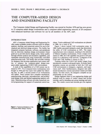
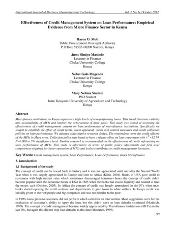
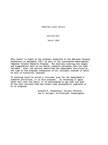
v. Backward, 1.5 G.paper. Develops an historical review as way toshow the evolution of the chairs over the timeas well as the current state of the art.At the end of the chapter expounds on all theprocedures that have been developed sincethe initial contact with the physical structure ofthe chair by plane to the development of aCAD model that allows the reliableperformance of a whole set of computersimulations.Paragraph 25,562 develops the followingrequirements in the development of the twodynamic tests, comprising positioning the chairshould be described in relation to themovement, the speed during the collision anddeceleration forces to achieve minimum. In thefirst test the dynamic forces are applied mainlyin the vertical direction and in the second testdownward forces predominate in thelongitudinal forward.The first scheduled air service came toJanuary 1, 1914, with the invention and use ofthe seaplane carrying a single passenger overthe Tampa Bay, St. Petersburg, Florida. Theworld's first airplane passenger appeared in1919 with 26 seats Lawson Airliner, wascomposed of two rows of seats designedbased wicker woven arranged throughout thecabin together with its huge windows celluloid,see Figure 3-4. [3]Figure 3-1The oldest aircraft seatIn 1930 with the softening of prices of purealuminium, the Aluminium Company ofAmerican (Alcoa) introduced the world's firstseat constructed from aluminium, eliminatingthe problems of warping, combustibility andinfestations associated with wood models. Forexample, three years equipped its Boeing 247with two rows of such seats.Figure 2-2 Certification Test Requirements3. Scope of the Concept ModelStudyFigure 3-2 First seat developed in aluminium and itscommercial application at Boeing3.1. Historical Review3.2. State-of-the-art: Economy ClassIn the aeronautical world exists a varied rangeof models of chairs, ranging in size, shape,comfort, totally dependent on the context inwhich they operate. Throughout this chapterwe present the main distinguishing factorsbetween various concepts in an attempt tolocate the chair model that is addressed in thisBefore make a comprehensive presentation ofsome of the most innovative concepts of seatsin use or under development, will show upcertain keywords that should be in mind on thedevelopment of new conceptions. As a note ofdifferentiation, the blocks at green are features3
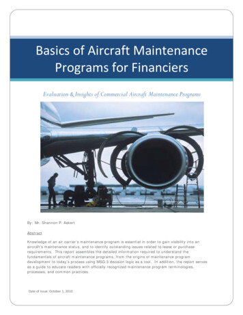
to take into account the perspective of theairline, while others are related to theperspective of the user.3.3. Presentation of the ModelSome parts of the original structure in thepresent work was based as a starting point forthe development of a new concept areexemplified in the figure 3-6. The approachconsisted in dismantling one piece at all themain components of the structure which couldinfluence absorption and the driving efforts,while important physical testing for certification.Figure 3-3 Relevant keywords in the evaluation of newconcepts3.2.1. Recaro - BL3520Figure 3-6 Photos to Model Study, obtained in TAP 3.3.1. CAD ModelingIn general, in geometric terms can split theuniverse of structural components into twogroups, one with respect to components withdefined geometric shapes and other geometricshapes not defined. We understand that thecomponents defined geometric shapes thatcan be defined geometrically by points, linesand circles, geometric shapes are not definedas those in which it is impossible to extract anytangible measure for later playback CAD.Figure 3-4 Presentation of the Recaro BL3520 [4]It takes only four keywords for a simple way todescribe this new set of Recaro seats:Habitability Maximized, Improved Comfort,Cost Reduction and Design Catchy.3.2.2. Aereas Seat ProjectFigure 3-5 Presentation of the Aereas Seat Project[42,43]This new idea is collaboration between GeinerAerospace, the Kobleder Knittec andLukedesign.Encompassingdesign,development and construction of a new seatthat sets new standards in terms of comfort,weight, design and materials costs using latestand innovative.Figure 3-7 A component of the real modelFor the construction of most the componentson the assembly of the three-dimensionalmodel was used CAD software AutodeskInventor Professional 2013 . In the figuresbelow shows the method explained above forthe construction of component 20 usingseveral benchmarks for the preparation ofsketch of the outside and cavity of thecomponent.4
Figure 3-10 Final Model of Sheet Support CoastsFigure 3-8 The construction of one componentThere were, however, other components thatare presented as a challenge, due to the nonspecificity of their contour shapes. Unlike theprevious component and the other examined,there were two requiring the use of anothersurface modeling software Alias Automotive2013 Autodesk .Figure 3-11 The Final Model4. Materials used in thestructureLike all equipment used in the aircraft industry,the criteria for selection of materials for thestructure of the seating system mainly consistsof six assumptions: high mechanical strength,significant extensions to avoid brittle fracture,good corrosion resistance, low density toreduce weight, machinability and formability,and last but not least the question of price.Figure 3-9 Reference PlansA key point lies in the dimensional adjustmentof views used. Given that the shootingdistance may vary, we used a referencevolume to ensure that the three views weresynchronized with each other, and representthe original dimensions of the physical model.Figure 4-1 Mounting Assembly Seat Frame for StaticTesting5
For the components of high-tensile steelpresent in the structure methodology of choicewas then also based on the availability BOMsimulation software adopted. Thus we usedthe 4130 steel with a temper heat treatment at425 C, leaving a yield of approximately 1190MPa.Finally with regard to ferrous metals, there isset the type of material used for example in thedesign of the print seat, or the type of stainlesssteel used. Unlike the vast majority of the othermaterials used in the seat, this component isnot made from aluminium alloys, requiringstrength, fatigue resistance and conformationrequirements that are only achievable with theapplication of ferrous metals. For the samereasons that the earlier the choice fell on 302cold rolled steel.Figure4-2 Correspondence Table Material Type vs ColorThe majority of the components present in thestructure are composed by aluminium alloys.With respect to the set of machinedcomponents, it is noted that a large part of thematerial 'raw' is waste, it is then preferable toselect an alloy of lower cost, but at the sametime guaranteeing all the requirements ofresistance, appearance and maintenance. Thechoice fell to the alloy 2024-T6, so it wasdecided initially by one whose thermaltreatment gave him added strength.For choose of polymeric material the firsthighlight that we need to have is someproperties and specifications that the materialmust possess in order to play a full role in theenvironment in which it operates:For the set of stampings preference for thechoice of alloy 6061-T651 is due to thesuitability for these shows the manufacturingprocess of stamping. As in the previous case itwas decided to heat treatment as to conferimproved mechanical properties. MechanicalResistancetoImpact(dimensional stability under tension,compression) Fracture Toughness Vibration and Shock Absorption Low Coefficient of FrictionIn terms of wear resistance andflammability properties ABS displaysgood, hence the choice.We grouped in the subset of all componentsextruded components that are possible toobtain by aluminium profile (extruded),although they can be subsequently subjectedto light machining operations. For this type ofcomponents was chosen choice of alloy 7075T651.5. Study ModelsThe method of selecting the type of springsteel to fit for this type of component was updue almost exclusively to the options that areavailable simulation software. The only steel ofthis type available was 1080. The choice fellon the laminate 1080 in the state as it was thisthat possessed better mechanical properties interms of strength.Are developed one model to make thesimulation of static certification and another toperform the simulation of the dynamiccertification. In the first case it was decided tobuild a seat frame of two places, whileremaining faithful to the original model, wherethe load was applied to the structure through apunctual distribution of forces. For the secondcase it was decided to simplify the model sincethe computational effort involved is indeed farsuperior when compared to the previous test,adopting a structure from one place only. Inthe second trial used a simplified model of adummy for the application of efforts in the seatframe. The model was in a sitting position andThen the approach is high-strength steels usedin aerospace components obtained throughthe forging process. The criterion of separationbetween this type of steel and the other relatesto the value assigned to the yield stress, whichis the first about 1200 MPa.6
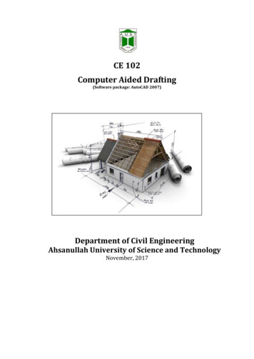
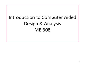
their movements were constrained by the useof a safety belt fixed to the support structure.to deform well. In the Figure 5-1 (green) showsthe overall constraint applied at four points ofthe base of the structure simulating a fixationof the floor of the plane, and the pattern ofdistribution of the nodal load vectors (in blue).Figure 5-3 shows, by way of example, a statictest in the upward direction.5.1. Model Structure for StaticTesting5.2. Model Structure for DynamicTestingFigure 5.1 Loading and ConstraintsFigure 5-4 Representation of the Model Seat Framewith DummyFigure 5-5 Test for Dynamic Seat Certification [7]Figure 5-2 Zones of Contact between SurfacesIn Figure 5-4, the right side (rose) to highlightthe areas that have been defined as o-SurfaceContact)therebyinterpenetration between meshes. All contactsurfaces between the dummy and the structureof the chair have been customized (FrictionlessContact) as elements slip between the legsand trunk of the dummy (Frictionless Slide),and all surfaces of the chair support that willcome into collision with the static block. In theleft (green) shows the constraints applied tothe chair structure allowing only the rectilinearmovement towards and collision block(Orange) vectors representing the initialvelocity imposed to the assembly.Figure 5-3 Test for Static Seat Certification [7]On the Figure 5-2 to enhance the surface(rose), which is defined as possible contactsurfaces between components, thus avoidingthe interpenetration of meshes, since with thisloading plate of the seat will tend to deforminto contact with the tube support and forcing it7
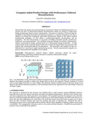
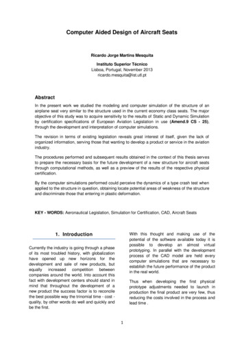
sustaining the passenger tried to makesweeping changes in the state of stress acrossmultiple nodes, transversely and longitudinallyrespect to the direction of application of load.6. Presentation and Discussionof Results6.1. Results of Static TestsAn Static Certification Essay according to CS25.561 6 G's vertically downwards uses asreference an occupant of 77 kg's: 𝟏𝟖𝟐 𝑵 𝟐𝟓 𝒗𝒆𝒕𝒐𝒓𝒆𝒔 4550 𝑁 𝑝𝑜𝑟 𝑎𝑠𝑠𝑒𝑛𝑡𝑜 77 𝐾𝑔 ′ 𝑠 9.81 𝑚 𝑠 2 𝟔 𝑮′ 𝒔 4532𝑁Figure 6-3 Sensitivity of the tension along the legstructureFigure 6-1 Graph Curve Applied LoadFigure 6-4 Sensitivity of the progression of tension inthe structureAnalysing the graph of the evolution of thevoltage set points marked along the seat frame(Figure 6-4), and also taking into account whatis comprised in the previous paragraph inrelation to the cross-state voltage componentcan be assume the critical path transmissionefforts over the structure of the seat for thestatic test is one which is represented by thedashed line representation in the left side ofFigure 6-4.Figure 6-2 State of Stress in the structure at time0.0128sFigure 6-2 depicts the tension state of theentire structure, during the time of maximumforce at time 0.0128 seconds differencesbetween the two figures resides in the fact thatin the left figure of the seat plates are notrepresented, and the range of graphicalrepresentation of the voltage is between 0-250MPa. The structural material with lower yieldstressthisthroughoutthestructurecorresponds to the 6061-T651 with 262 MPa,thus observing the image on the right of Figure7-2 it can be seen that the plastic deformationis virtually non-existent, except for some pointswhere it is natural outweighs unrealistically.7. Dynamic Test ResultsAs the whole structure is mainly calculatedbased on several components of aluminiumalloys, will be to limit the spectrum of stressdistribution to the yield stress of the alloy withthe highest yield point, the alloy Al 7075 with avoltage yield of 500 MPa.In order to understand how efforts aretransmitted along the leg structure, understoodin this case as a critical component in terms of8
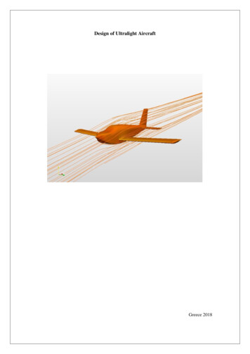
Figure 7-3 Representation of the Safety Factor, andPlastic Deformation ZonesFigure 7-1 State of Tension in the Structure on lastinstant of timeReferring to Figure 7-3, the right imagerepresents the various zones which haveundergone plastic deformation, however, byanalysing the distribution of the safety factorregarding the tensile strength of variousmaterials can conclude that there are at leastfive components who are at risk of collapse,and surface tension very close to the tensilestrength.In figure 7.1 we can see the state of tension ofthe whole structure to the last time point inwhich it was possible to get results. Justlooking for structural components made fromaluminium, it can be seen that there are twocomponents (marked with two arrows) ofgreatest importance to maintain the integrity ofthe structure, being critical components to beanalysed. Given that the yield strength of thismaterial is 500 MPa, then these componentsare on the threshold of plastic deformation.8. ConclusionsIt was necessary to make some simplificationsin three-dimensional models developed withCAD software, and models of finite elementanalysis in order to manage to obtain validresults in an attempt to develop thecertification process of the structure throughcomputational simulations. Based on theinfluence of these simplifications, the results donot allow the exclusion of physical tests forcertification purposes. However, the model ofwork throughout the thesis allows to develop apreliminary analysis will approximate s of the concept, and thus reducingthe number of physical tests required until finalcertification.Figure 7-2 Sensitivity of the progression of the tensionin critical componentLooking in more detail the evolution voltage tovarious nodes throughout the criticalcomponent, it appears that four of the nodesrepresented already reached the point ofmaximum tension and maintaining this uniformuntil the end of simulation. Thus it can beinferred that the time interval was sufficient tosimulate the structure is subject to itsmaximum deflection.Regarding computer simulations performed,we can conclude that the structure does notundergoplasticdeformationmodelledremarkable to compromise the physicalintegrity and safety of the passengers due tothe collapse of same after an emergencylanding, according to the requirements ofStatic Testing and Certification dynamic(according to CS 25.561 and CS 25,562).After completion of this study looks a possiblefuture work. To improve the current framewhile maintaining the mechanical strength on9
the certification tests, reducing the number ofcomponents and optimizing the same, therebyreducing the weight of the structure. At thesame time attention should revert to the user,trying to adjust the seat position of each userunder the optimal conditions of temperatureand humidity body. In short keywords and howguidelines for the project, should try to mount aconcept that is simultaneously: lightweight,simple,customizable,attractive, environmentallyfriendly, comfortable, adjustable and finallyrelatively index.php/Aircraft Certification and Production Standards[2] Certification Specifications for LargeAeroplanes, CS-25; Book 1 – AirworthinessCode; Emergency Landing Conditions, CS25.561[3] Information found “The evolution of theAirline Seat” in web, at 5/From-Wicker-to-Wow#slide 1[4] Information found in web, at 12-02-13:http://www.recaro-as.com/bl3520.html[5] – Image found in web, at ?attachment id 189[6] – Image found in web, at innovationen/aerasseat-project/[7] Images found in web pages/en/news/etso-c127aauthorisation-test.php10
Computer Aided Design of Aircraft Seats Ricardo Jorge Martins Mesquita Instituto Superior Técnico Lisboa, Portugal, November 2013 ricardo.mesquita@ist.utl.pt Abstract In the present work we studied the modeling and computer simulation of the structure of an airplane seat very similar