Transcription
Dell Latitude D630 Service ManualBefore You BeginUsing CardsMedia Bay DevicesHard DriveHinge CoverKeyboardMemoryDisplay AssemblyInternal Card With Bluetooth Wireless TechnologyCommunications CardsCoin-Cell BatteryPalm RestModemProcessor Thermal-Cooling AssemblyProcessorPC Card ReaderSpeakerSystem BoardFanFlashing the BIOSNotes, Notices, and CautionsNOTE: A NOTE indicates important information that helps you make better use of your computer.NOTICE: A NOTICE indicates either potential damage to hardware or loss of data and tells you how to avoid the problem.CAUTION: A CAUTION indicates a potential for property damage, personal injury, or death.Information in this document is subject to change without notice. 2007 Dell Inc. All rights reserved.Reproduction in any manner whatsoever without the written permission of Dell Inc. is strictly forbidden.Trademarks used in this text: Dell, the DELL logo, and Latitude are trademarks of Dell Inc.; Microsoft, Windows, and Windows Vista are either trademarks or registered trademarks ofMicrosoft Corporation; Bluetooth is a registered trademark owned by Bluetooth SIG, Inc. and is used by Dell under license.Other trademarks and trade names may be used in this document to refer to either the entities claiming the marks and names or their products. Dell Inc. disclaims anyproprietary interest in trademarks and trade names other than its own.September 2009Rev. A01
Back to Contents PageBefore You BeginDell Latitude D630 Service ManualRecommended ToolsTurning Off Your ComputerBefore Working Inside Your ComputerThis section provides procedures for removing and installing the components in your computer. Unless otherwise noted, each procedure assumes that thefollowing conditions exist:lYou have performed the steps in Turning Off Your Computer.lYou have read the safety information in the Dell Product Information Guide.lA component can be replaced or—if purchased separately—installed by performing the removal procedure in reverse order.Recommended ToolsThe procedures in this document may require the following tools:lSmall flat-blade screwdriverlPhillips screwdriverlSmall plastic scribel5-mm hex nut driverlFlash BIOS update program CDlProcessor extraction toolTurning Off Your ComputerNOTICE: To avoid losing data, save and close all open files and exit all open programs before you turn off your computer.1.Shut down the operating system:a.Save and close all open files and exit all open programs.b. In the Microsoft Windows XP operating system, click Start Shut Down Shut down. In Microsoft Windows Vista , click the Windows Vista Start buttoncorner of the Start menu as shown below, and then click Shut Down.in the lower-left corner of the desktop, click the arrow in the lower-rightThe computer turns off after the operating system shutdown process is complete.2.Ensure that the computer and all attached devices are turned off. If your computer and attached devices did not automatically turn off when you shutdown your operating system, press and hold the power button for about 4 seconds to turn them off.Before Working Inside Your ComputerUse the following safety guidelines to help protect your computer from potential damage and to help ensure your own personal safety.CAUTION: Before you begin any of the procedures in this section, follow the safety instructions in the Product Information Guide.CAUTION: Handle components and cards with care. Do not touch the components or contacts on a card. Hold a card by its edges or by its metalmounting bracket. Hold a component such as a processor by its edges, not by its pins.CAUTION: To avoid electrostatic discharge, ground yourself by using a wrist grounding strap or by periodically touching an unpainted metalsurface, such as a connector on the back of the computer.CAUTION: Many repairs may only be done by a certified service technician. You should only perform troubleshooting and simple repairs asauthorized in your product documentation, or as directed by the online or telephone service and support team. Damage due to servicing that is notauthorized by Dell is not covered by your warranty. Read and follow the safety instructions that came with the product.
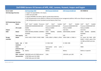
NOTICE: Handle components and cards with care. Do not touch the components or contacts on a card. Hold a card by its edges or by its metalmounting bracket. Hold a component, such as a processor, by its edges, not by its pins.NOTICE: When disconnecting a cable, pull on the cable's connector or on its pull-tab, not on the cable itself. Some cables have connectors withlocking tabs; before disconnecting this type of cable, press inward on the locking tabs to release the connector. When connecting or disconnectinga cable, ensure that the connectors are correctly oriented and aligned to avoid damage to the connector and/or the connector's pins.NOTICE: To avoid damaging the computer, perform the following steps before you begin working inside the computer.1.Ensure that the work surface is flat and clean to prevent the computer cover from being scratched.NOTICE: To avoid losing data, save and close any open files and exit any open programs before you turn off your computer.2.Save and close any open files, exit any open programs, then shut down the operating system and turn off all attached devices: In the Microsoft Windows Vista operating system, click Start, click the arrowicon, and then click Shut Down.In the Microsoft Windows XP operating system, click Start Shut Down Shut down.The computer turns off after the operating system shutdown process finishes.NOTE: Ensure that the computer is off and not in a power management mode. If you cannot shut down the computer using the operating system,press and hold the power button for 4 seconds.3.Disconnect your computer and all attached devices from their electrical outlets.NOTICE: To disconnect a network cable, first unplug the cable from your computer, and then unplug it from the network device.4.Disconnect all external cables from the computer.5.Close the display and turn the computer upside down on a flat work surface.6.Remove the battery:1a.Slide the two battery-bay latch releases on the bottom of the computer toward the sides of the computer until they are engaged.b.Grasp the battery by the battery tab, and then slide the battery horizontally toward the front of the computer.c.Lift the battery from the battery bay.battery2battery-bay latch releases (2)3battery tab7.Turn the computer over and press the power button to ground the system board.8.Remove the PC Card or ExpressCard, if installed, from the PC Card slot (see Removing a PC Card or Blank).9.Remove the smart card, if installed, from the smart card slot (see Removing a Smart Card).Back to Contents Page
Back to Contents PageFlashing the BIOSDell Latitude D630 Service ManualFlashing the BIOS From a CDFlashing the BIOS From the Hard DriveIf a BIOS-update program CD is provided with the new system board, flash the BIOS from the CD. If you do not have a BIOS-update program CD, flash theBIOS from the hard drive.Flashing the BIOS From a CD1.Ensure that the AC adapter is plugged in and that the main battery is installed properly.NOTE: If you use a BIOS-update program CD to flash the BIOS, set up the computer to boot from a CD before inserting the CD.2.Insert the BIOS-update program CD, and restart the computer.Follow the instructions that appear on the screen. The computer continues to boot and updates the new BIOS. When the flash update is complete, thecomputer automatically reboots.3.Press F2 during POST to enter the system setup program.4.Press Alt and F to reset the computer defaults.5.Press Esc , select Save changes and reboot, and press Enter to save configuration changes.6.Remove the flash BIOS-update program CD from the drive and restart the computer.Flashing the BIOS From the Hard Drive1.Ensure that the AC adapter is plugged in, the main battery is properly installed, and a network cable is attached.2.Turn on the computer.3.Locate the latest BIOS update file for your computer at support.dell.com.4.Click Download Now to download the file.5.If the Export Compliance Disclaimer window appears, click Yes, I Accept this Agreement.The File Download window appears.6.Click Save this program to disk and then click OK.The Save In window appears.7.Click the down arrow to view the Save In menu, select Desktop, and then click Save.The file downloads to your desktop.8.Click Close if the Download Complete window appears.The file icon appears on your desktop and is titled the same as the downloaded BIOS update file.9.Double-click the file icon on the desktop and follow the instructions on the screen.Back to Contents Page
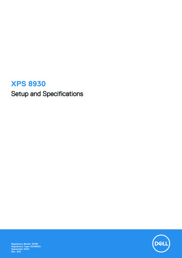
Back to Contents PageInternal Card With Bluetooth Wireless TechnologyDell Latitude D630 Service ManualCAUTION: Before you begin any of the procedures in this section, follow the safety instructions in the Product Information Guide.CAUTION: To avoid electrostatic discharge, ground yourself by using a wrist grounding strap or by periodically touching an unpainted metalsurface, such as a connector on the back of the computer.NOTICE: To avoid damaging the system board, you must remove the main battery before you begin working inside the computer (see BeforeWorking Inside Your Computer).If you ordered an internal card with Bluetooth wireless technology with your computer, it is already installed.To replace the internal card with Bluetooth wireless technology:1.Follow the procedures in Before You Begin.2.Remove the hinge cover (see Hinge Cover).NOTICE: Be careful when removing the card to avoid damaging the card, card cable, or surrounding components.3.Remove the card cable from its routing guide.1connector wire2plastic scribe4metal securing tab5front plastic securing-tab3back plastic securing-tab4.While grasping the card cable with one hand, press slightly downward on the back plastic securing-tab with a plastic scribe to release the cable end ofthe card.5.Continue to grasp the card cable with one hand while prying the card out from underneath the metal tab with the other hand.1cable2card connector4metal tab5plastic scribe3card
6.Lift the card from the compartment, ensuring that you do not pull on the card cable with excessive force.7.Disconnect the card from the cable and remove the card from the computer.8.Connect the new card to the cable.9.Rotate and slide the card under the metal securing tab.10.Replace the hinge cover (see Hinge Cover).Back to Contents Page
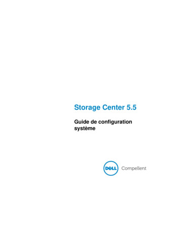
Back to Contents PagePC Card ReaderDell Latitude D630 Service ManualCAUTION: Before you begin any of the procedures in this section, follow the safety instructions in the Product Information Guide.CAUTION: To avoid electrostatic discharge, ground yourself by using a wrist grounding strap or by periodically touching an unpainted metalsurface, such as a connector on the back of the computer.1.Follow the instructions in Before You Begin.2.Remove any installed media bay device (see Media Bay Devices).3.Remove the hinge cover (see Hinge Cover).4.Remove the keyboard (see Removing the Keyboard).5.Remove the palm rest (see Palm Rest).6.Remove the four M2 x 3-mm screws that secure the PC Card reader to the computer.1PC Card reader2M2 x 3-mm screws (4)3pull-tabNOTICE: To avoid damaging the PC Card reader connector, do not rotate or rock the connector as you remove it. Use firm and even pressure tolift the pull-tab vertically.7.Use the pull-tab to disconnect the PC Card reader connector from the system board.Back to Contents Page
Back to Contents PageCoin-Cell BatteryDell Latitude D630 Service ManualCAUTION: Before you begin any of the procedures in this section, follow the safety instructions in the Product Information Guide.CAUTION: To avoid electrostatic discharge, ground yourself by using a wrist grounding strap or by periodically touching an unpainted metalsurface, such as a connector on the back of the computer.NOTICE: To avoid damaging the system board, you must remove the main battery before you begin working inside the computer (see BeforeWorking Inside Your Computer).To replace the coin-cell battery:1.Follow the procedures in Before You Begin.2.Remove the hinge cover (see Hinge Cover).3.Remove the keyboard (see Removing the Keyboard).1battery cable connector2coin-cell battery3plastic mylar4.Remove the battery cable connector from the connector on the system board.5.Being careful not to break the plastic, slightly raise the corner of the plastic mylar above the battery.6.While holding the plastic mylar slightly up, grasp the battery and pull it out of the battery compartment.7.Place the new battery under the plastic mylar in the battery compartment.8.Connect the battery cable connector to the connector on the system board.9.Replace the keyboard (see Replacing the Keyboard).10.Replace the hinge cover (see Hinge Cover).Back to Contents Page
Back to Contents PageProcessorDell Latitude D630 Service ManualRemoving the ProcessorInstalling the ProcessorRemoving the ProcessorCAUTION: Before you begin any of the procedures in this section, follow the safety instructions in the Product Information Guide.CAUTION: To avoid electrostatic discharge, ground yourself by using a wrist grounding strap or by periodically touching an unpainted metalsurface, such as a connector on the back of the computer.NOTICE: To prevent intermittent contact between the ZIF-socket cam screw and the processor when removing or replacing the processor, pressto apply slight pressure to the center of the processor while turning the cam screw.NOTICE: To avoid damage to the processor, hold the screwdriver so that it is perpendicular to the processor when turning the cam screw.1.Follow the instructions in Before You Begin.2.Remove any installed media bay device (see Media Bay Devices).3.Remove the hinge cover (see Hinge Cover).4.Remove the keyboard (see Removing the Keyboard).5.Remove the palm rest (see Palm Rest).6.Remove the processor thermal-cooling assembly (see Removing the Processor Thermal-Cooling Assembly).NOTICE: When removing the processor, pull it straight up. Be careful not to bend the pins on the processor.7.To loosen the ZIF socket, use a small, flat-blade screwdriver and rotate the ZIF-socket cam screw counterclockwise until it comes to the cam stop.The ZIF-socket cam screw secures the processor to the system board. Take note of the arrow on the ZIF-socket cam screw.1ZIF socket8.2pin-1 corner of processor3ZIF-socket cam screwRemove the processor.Installing the ProcessorCAUTION: Before you begin any of the procedures in this section, follow the safety instructions in the Product Information Guide.
CAUTION: To avoid electrostatic discharge, ground yourself by using a wrist grounding strap or by periodically touching an unpainted metalsurface, such as a connector on the back of the computer.NOTICE: Ensure that the cam lock is in the fully open position before seating the processor. Seating the processor properly in the ZIF socket doesnot require force.NOTICE: A processor that is not properly seated can result in an intermittent connection or permanent damage to the processor and ZIF socket.1.Align the pin-1 corner of the processor so that it points to the triangle on the system board, and insert the processor into the ZIF socket.When the processor is correctly seated, all four corners are aligned at the same height. If one or more corners of the processor are higher than theothers, the processor is not seated correctly.NOTICE: To prevent intermittent contact between the ZIF-socket cam screw and the processor when removing or replacing the processor, pressto apply slight pressure to the center of the processor while turning the cam screw.2.Tighten the ZIF socket by turning the cam screw clockwise to secure the processor to the system board.3.Peel the backing off the thermal cooling pad and adhere the pad to the portion of the thermal-cooling assembly that covers the processor.4.Replace the processor thermal-cooling assembly (see Processor Thermal-Cooling Assembly).5.Replace the palm rest (see Palm Rest).NOTE: If necessary, ensure that you reconnect the coin-cell battery (see Coin-Cell Battery) before you replace the keyboard.6.Replace the keyboard (see Replacing the Keyboard).7.Replace the hinge cover (see Hinge Cover).8.Replace the media bay device (see Media Bay Devices).9.Replace the battery.10.Update the BIOS using a flash BIOS-update program CD (see Flashing the BIOS).Back to Contents Page
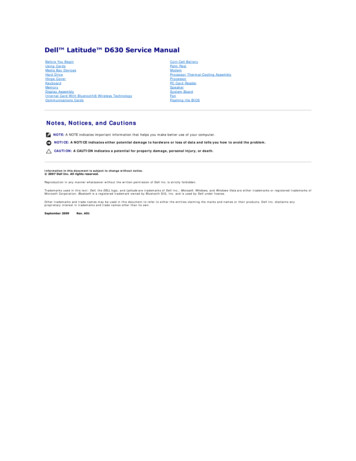
Back to Contents PageDisplay AssemblyDell Latitude D630 Service ManualRemoving the Display AssemblyRemoving the Display BezelRemoving the Display PanelRemoving the Display Panel BracketsRemoving the Display Panel CableRemoving the Display HingesRemoving the Display AssemblyCAUTION: Before you begin any of the procedures in this section, follow the safety instructions in the Product Information Guide.CAUTION: To avoid electrostatic discharge, ground yourself by using a wrist grounding strap or by periodically touching an unpainted metalsurface, such as a connector on the back of the computer.1.Follow the instructions in Before You Begin.2.Remove the hinge cover (see Hinge Cover).3.Remove the keyboard (see Removing the Keyboard).4.Review the cable routing diagram:1 WWAN/FCM cardconnector2 WWAN antenna cables3 WLAN antenna cables(black and white)4 WLAN card5 pull-tab6 display cable7 WLAN antenna cables(white and gray)8 WLAN antenna cable (gray;currently unused)NOTICE: To avoid damage to your computer, use the illustration above when replacing the display assembly to carefully reroute the cables in theappropriate cable channels. Route the gray and black antenna cables beneath the white antenna cable, and the black display cable on top of thewhite antenna cable.5.Pull straight up on the pull-tab that is attached to the display cable to disconnect the cable from the system board.6.Disconnect the antenna cables from their card(s) (see Communications Cards).7.Carefully remove the antenna cables and the display cable from their routing guides.8.Close the display.9.Turn the computer upside down with the back of the computer facing you.
10.From the back of the computer, remove the two M2.5 x 8-mm screws.11.From the bottom of the computer, remove the two M2.5 x 8-mm screws labeled "D."12.Turn the computer top-side up and open the display.1antenna cables (2)13.Lift the display assembly out of the computer base.2display cable pull-tabRemoving the Display BezelCAUTION: Before you begin any of the procedures in this section, follow the safety instructions in the Product Information Guide.CAUTION: To avoid electrostatic discharge, ground yourself by using a wrist grounding strap or by periodically touching an unpainted metalsurface, such as a connector on the back of the computer.1.Follow the instructions in Before You Begin.2.Remove the display assembly (see Display Assembly).3.Use a plastic scribe to pry the six rubber screw-covers/display-bumpers out of the screw holes on the front of the bezel.
1 screw covers/display bumpers (6)2 M2.5 x 5-mm shoulder screws (6)4 display panel5 top cover4.3 display bezelRemove the six M2.5 x 5-mm shoulder screws from the front of the bezel.NOTICE: Carefully separate the bezel from the top cover to avoid damage to the bezel.5.Starting from the inside edges of the bezel, use your fingers to pry the bezel upward and outward from the display panel. Release the sides of the bezelnext; if necessary, use a plastic scribe to release the corners of the bezel from the display panel.NOTICE: To avoid damaging the computer when replacing the display bezel, ensure that the bezel edges line up with those on the top cover, andsnap into place around the entire perimeter of the top cover.Removing the Display PanelCAUTION: Before you begin any of the procedures in this section, follow the safety instructions in the Product Information Guide.CAUTION: To avoid electrostatic discharge, ground yourself by using a wrist grounding strap or by periodically touching an unpainted metalsurface, such as a connector on the back of the computer.1.Follow the instructions in Before You Begin.2.Remove the display assembly (see Display Assembly).3.Remove the display bezel (see Removing the Display Bezel).4.Remove the three M2 x 3-mm screws from each side of the display panel.1display panel2M2 x 3-mm screws (6)4display cable5bracket tabs (4)3top coverCAUTION: To avoid damage to your display panel, handle the panel by the bracket tabs only.
5.Lift the display panel a few inches from the top cover.6.Draw the display cable pull-tab away from the top cover to release the display cable, and lift the display panel fully from the top cover.Removing the Display Panel BracketsCAUTION: Before you begin any of the procedures in this section, follow the safety instructions in the Product Information Guide.CAUTION: To avoid electrostatic discharge, ground yourself by using a wrist grounding strap or by periodically touching an unpainted metalsurface, such as a connector on the back of the computer.1.Follow the instructions in Before You Begin.2.Remove the display assembly (see Display Assembly).3.Remove the display bezel (see Removing the Display Bezel).4.Remove the display panel (see Removing the Display Panel).5.Remove the four M2 x 3-mm screws from each side of the display panel.1 displaypanel2 display panel brackets (2) (left andright of display panel)3 M2 x 3-mm screws (4 each onsides of display panel)Removing the Display Panel CableCAUTION: Before you begin any of the procedures in this section, follow the safety instructions in the Product Information Guide.CAUTION: To avoid electrostatic discharge, ground yourself by using a wrist grounding strap or by periodically touching an unpainted metalsurface, such as a connector on the back of the computer.1.Follow the instructions in Before You Begin.2.Remove the display assembly (see Display Assembly).3.Remove the display bezel (see Removing the Display Bezel).4.Remove the display panel (see Removing the Display Panel).5.Turn over the display panel and place it on a clean surface.NOTICE: To avoid damage to the computer when replacing the bottom flex cable, gently support the bottom of the inverter board with one fingeras you reseat the bottom flex-cable connector. Do not bend the inverter board.6.Gently pull the pull-tab on the bottom flex-cable connector to release the cable from the inverter board.7.Squeeze the flex-cable release levers at either side of the top flex-cable connector to release the connector.
1 top flex-cableconnector2 flex-cable release levers(2)3 back of display panel4 inverter board5 bottom flex-cableconnector6 pull-tab on bottom flex-cableconnectorRemoving the Display HingesCAUTION: Before you begin any of the procedures in this section, follow the safety instructions in the Product Information Guide.CAUTION: To avoid electrostatic discharge, ground yourself by using a wrist grounding strap or by periodically touching an unpainted metalsurface, such as a connector on the back of the computer.1.Follow the instructions in Before You Begin.2.Remove the display assembly (see Display Assembly).3.Remove the display bezel (see Removing the Display Bezel).4.Remove the display panel (see Removing the Display Panel).5.Remove the M2.5 x 5-mm screw from the right display hinge.1M2.5 x 5-mm screw4alignment pin2display hinges (2)(left and right)3top cover6.Lift the right display hinge off the two alignment pins and out of the top cover.7.Repeat step 5 and step 6 for the left display hinge.Back to Contents Page
Back to Contents PageFanDell Latitude D630 Service ManualCAUTION: Before you begin any of the procedures in this section, follow the safety instructions in the Product Information Guide.CAUTION: To avoid electrostatic discharge, ground yourself by using a wrist grounding strap or by periodically touching an unpainted metalsurface, such as a connector on the back of the computer.1.Follow the instructions in Before You Begin.2.Remove the system board (see Removing the System Board).3.Remove the M2.5 x 5-mm screw that secures the fan to the base.4.Lift the fan assembly out of the base.Back to Contents Page
Back to Contents PageHard DriveDell Latitude D630 Service ManualCAUTION: Before you begin any of the procedures in this section, follow the safety instructions in the Product Information Guide.CAUTION: Do not touch the metal housing of the hard drive if you remove the hard drive from the computer while the drive is hot.CAUTION: To avoid electrostatic discharge, ground yourself by using a wrist grounding strap or by periodically touching an unpainted metalsurface, such as a connector on the back of the computer.NOTICE: To prevent data loss, turn off your computer before removing the hard drive. Do not remove the hard drive while the computer is on orin a power management mode.NOTICE: To avoid damaging the hard drive, handle the drive with care.NOTE: Dell does not guarantee compatibility or provide support for hard drives from sources other than Dell.NOTE: You need the Operating System installation media to install the Microsoft Windows operating system. You also need the Drivers and Utilitiesmedia for your computer to install the drivers and utilities on a new hard drive.To replace the hard drive in the hard drive bay:1.1Follow the procedures in Before You Begin.hard drive screws (2)2.2hard driveTurn the computer over, and remove the two hard-drive screws.NOTICE: When the hard drive is not in the computer, store it in protective antistatic packaging.3.Slide the hard drive out of the computer.4.Remove the bezel screw and the bezel from the hard drive.5.Remove the new drive from its packaging.Save the original packaging for storing or shipping the hard drive.NOTICE: Use firm and even pressure to slide the drive into place. If you use excessive force, you may damage the connector.6.Attach the bezel to the new hard drive with the bezel screw.7.Slide the hard drive into the bay until it is fully seated.8.Replace and tighten the two hard-drive screws.9.Use your Operating System installation media to install the operating system for your computer (see your User's Guide for information).10.Use the Drivers and Utilities media to install the drivers and utilities for your computer (see your User's Guide for information).Back to Contents Page
Back to Contents PageHinge CoverDell Latitude D630 Service ManualCAUTION: Before you begin any of the procedures in this section, follow the safety instructions in the Product Information Guide.CAUTION: To avoid electrostatic discharge, ground yourself by using a wrist grounding strap or by periodically touching an unpainted metalsurface, such as a connector on the back of the computer.NOTICE: The hinge cover is fragile and can be damaged if extreme force is used. Be careful when removing the hinge cover.1.Follow the procedures in Before You Begin.2.Open the display all the way (180 degrees) so that the display rests flat on your work surface.NOTICE: To avoid damaging the hinge cover, do not lift the cover on both sides simultaneously. Removing the hinge cover in a different way thandescribed may cause the plastic to break.1hinge cover3.2plastic scribe3indentStarting on the right side of the computer, use a plastic scribe (inserted into the indent) to pry up the hinge cover. Lift the cover away from the computergoing from the right toward the left, and then lay the cover aside.NOTICE: Before installing the hinge cover, ensure that all cables are routed correctly. Improper routing of the cables can cause damage to thecables.To replace the hinge cover:1.Insert the left edge of the cover into place.2.Press from left to right until the cover snaps into place, ensuring that the hinge cover edges line up with those on the palm rest.Back to Contents Page
Back to Contents PageKeyboardDell Latitude D630 Service ManualRemoving the KeyboardReplacing the KeyboardRemoving the KeyboardCAUTION: Before you begin any of the procedures in this section, follow the safety instructions in the Product Information Guide.CAUTION: To avoid electrostatic discharge, ground yourself by using a wrist grounding strap or by periodically touching an unpainted metalsurface, such as a connector on the back of the computer.1.Follow the instructions in Before You Begin.2.Remove the hinge cover (see Hinge Cover).NOTICE: The keycaps on the keyboard are fragile, easily dislodged, and time-consuming to replace. Be careful when removing and handling thekeyboard.3.Remove the three screws at the top of the keyboard.1screws (3)2keyboard tab (5)3palm rest4pull-tab5keyboard-cable locking arm6keyboard cable connector7retaining bracketNOTE: Lift the keyboard carefully to ensure that you do not pull on the keyboard cable.4.Ease the edges of the keyboard out of the small detents on the sides, then slide the keyboard slightly forward to free the keyboard tabs from the palmrest.5.Rotate the top of the keyboard forward and away from the display, and lay it upside-down on the palm rest to gain access to the keyboard connector.6.If the keyboard cable is held in place by a locking arm next to the keyboard connector, carefully spread the retaining bracket away from the connector sothat you can pivot the keyboard-cable locking arm upward to release the cable.7.Pull up on the pull-tab to disconnect the keyboard cable connector from the keyboard connector on the system board.Replacing the KeyboardCAUTION: Before you begin any of the procedures in this section, follow the safety instructions in the Product Information Guide.CAUTION: To avoid electrostatic discharge, ground yourself by using a wrist grounding strap or by periodically touching an unpainted metalsurface, such as a connector on the back of the computer.
NOTICE: To avoid scratching the palm rest when replacing the keyboard, hook the tabs along the front edge of the keyboard into the palm rest,and then secur
The computer turns off after the operating system shutdown process finishes. 3. Disconnect your computer and all attached devices from their electrical outlets. 4. Disconnect all external cables from the computer. 5. Close the display and turn the computer upsi