Transcription
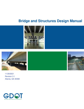
Bridge and Structures Design Manual11/29/2021Revision 3.1Atlanta, GA 30308
DisclaimerThis manual is intended to be an aid to designers working on projects for the GeorgiaDepartment of Transportation. It is not to be used as a substitute for sound engineeringpractice and will be used at one’s own risk. The Georgia Department of Transportation andthe authors of this document are not responsible for the consequences of the use andmisuse of the contents of this document.The latest version of this document is available s/BridgeandStructure/GDOT Bridge andStructures Policy Manual.pdfBasic drawings, MicroStation customization tools, design programs, and other helpfulresources can be accessed from the Office of Bridge Design and Maintenance home ges/OfficeDivisionsDetails.aspx?officeID 25Please send constructive comments to the Bridge Design LRFD Committee care of DouglasFranks: dfranks@dot.ga.gov.
AcknowledgementThe original Bridge and Structures Design Manual was created through the public-private partnershipof the Georgia Department of Transportation and the Consulting Engineering Companies of Georgia.This document was modified from the original Design Manual for inclusion of LRFD material andgeneral content by Georgia Department of Transportation personnel. The following people havedonated their time and resources to contribute to the quality of transportation engineering in Georgia:LRFD Design CommitteeY. Stanley Kim, PhD, P.E. – GDOTDouglas D. Franks, P.E. – GDOTSteven K. Gaston, P.E. – GDOTNathan Wilson, P.E. – GDOTEric Fleckenstein, P.E. – GDOTEric Huibregtse, P.E. - GDOTDesign Committee for Original DocumentPaul V. Liles, Jr., P.E. – GDOTTed Cashin, P.E. – GDOTAl Bowman, P.E. – The LPA Group IncorporatedJohn Heath, P.E. – Heath and Lineback EngineersGreg Grant, P.E. – Wolverton and AssociatesContributing Authors to Original DocumentBob Mustin, P.E. – GDOTJohn Tiernan, P.E. – GDOTJohn Durand, P.E. – Parsons BrinckerhoffPage i
Intentionally Left BlankPage ii
Bridge and Structures Design ManualRevision SummaryRevision NumberRevision DateRevision SummaryLRFD Bridge ManualOriginal7/8/13Original Release Date1.010/1/13Section 3.2.3.3 - Removed “after all necessarygrinding” from 8” overhang thickness; Removed“(LRFD 13.7.3.1.2)” from 8” overhang thicknessSection 3.5.2.1 - Changed LRFD reference fromTable 4A-1 to Table A4-1Section 4.4.2 - Modified tower bent placementdirective; Added pile fixity assumption2.06/2/14Section 3.2.2.3 - Removed CommentarySection 2.1 - Updated LRFD Specification to 6thedition, 2012; updated Georgia StandardSpecification to 2013; defined all bridges as “typical”Section 2.2.2.2 - Allowed Standard Specificationwidening of Existing Standard Specification bridgesSection 2.4 - Changed office responsible for SurveyManualSection 2.8 - Added LRFD software submittalrequirements for consultantsSection 3.1.1 - New section added - Set minimumbeam requirement for bridges with vehicular trafficSection 3.2.2.1 - Added reference to online slabdesign programSection 3.2.2.4.2 - Changed placement and spacingof temperature steel in top mat of deckSection 3.3.2.2.1 - Clarified urban area locationsSection 3.3.2.2.2 - Edited height of fenceSection 3.4.3.15.4 - New section added – limitingcoping thickness to 6”Section 3.12.2.3.1 - Check clearance between capand PSC beam when plain pads are usedSection 3.12.2.5.2 - Added new section - Directiveto minimize number of pad designs for bridgeSection 4.2.1 - Specified use of kips in lieu of tonsor pounds for foundationsSection 4.2.2.3, 4.2.2.4, 4.2.2.5 - Added maximumfactored resistances and stresses for all pile typesSection 4.2.3.4 - Restricted use of spirals incaisson; limited ties to maximum size of #6; Statedseismic detailing at fixity is not required in caissonsSection 4.4.1.2.1 - Added limits for depth to widthPage iii
Bridge and Structures Design Manualratio of intermediate caps; Changed cap widthincrement to 3”Section 4.4.1.2.2 - Modified longitudinal rebar inriser of intermediate bents to # 5Section 4.4.1.3 - Removed railroad from vehicularcollision considerationBridge Design ManualOriginal1/26/15General - Incorporated Standard Specificationguidance from GDOT Bridge and Structures DesignManual into LRFD Bridge Manual to produce aconsolidated manualSection 1.3.3 - Added requirement to submit designcalculations in PDF formatSection 1.4.3.1 - Added guidance for when a decksection is required on preliminary layoutsSection 1.6.9.2.2 - Removed direction about railroadshoring reviewSection 1.6.9.2.4 - Added reference to 8.2.10Section 3.2.4 - Revised requirement for epoxyreinforcementSection 3.2.5 - Removed requirement for groovingunder mediansSection 3.3.2.2 - Modified description of new curvedfence detailSection 3.3.2.2.1 - Clarified directive for the use ofhandrail or fence on parapetsSection 3.4.1.2.1 - Removed restriction on use of0.6” diameter strandsSection 3.4.2.6.2 - Limited coping thickness to beused for composite propertiesSection 3.4.2.7, 3.5.2.2 - Limited beam spacing to9’-0”Section 3.6.2 - Added the use of “weathering steel”Section 3.9.1.1 - Added provisions for use of steeldiaphragms for concrete beamsSection 3.15.1 - Revised Drainage ManualreferenceSection 4.2.2.2 - Modified “Factored Axial Load”noteSection 4.2.2.3 - Clarified directive on use of 50 ksiH-piles versus 36 ksi H-pilesSection 4.2.2.4 - Removed 12” PSC piles fromTableSection 4.2.2.5 - Added 20” and 24” metal shellpiles to TablePage iv
Bridge and Structures Design ManualSection 4.2.3.4 - Added 5” clear spacing asminimum for stirrups and vertical bars in caissonsSection 4.3.4 - Modified wingwall length requirementSection 4.4.1.2.4 - Increased minimum stirrupspacing to 5”Section 4.4.1.3 - Added 4” minimum stirrup spacingrequirement for columnsSection 5.1.1.1 - Revised Table to change ModularWalls to Modular Block WallsSection 5.5.5 - Limited Modular Block Wall designheight to 20 feetSection 8.1.1.1 - Modified when bridge plans requirea revision markSection 8.2.10 - Added direction about railroadshoring reviewSection 9.2.1 - Added directive to include SeismicZone and SD1 on General Notes sheet1.05/5/15Section 2.1 - Updated LRFD Specification to 7thEdition, 2014Section 2.1.3 - Removed Guide Specificationreference; contact Bridge Office for guidanceSection 2.3.3.1 - Added for vertical clearances to besatisfied for travelwaySection 3.4.1.2.4 - Added that draped strands shallnot be placed in the top 8” of beamSection 4.2.2.2 - Added guidance in reference toinformation needed in bridge plans for fieldmeasurement of driving resistance for piles forLRFD projects.Section 4.3.2, 4.4.2.1 - Added guidance that 5.10.8need not apply to side faces of bent caps less thanor equal to 2 foot high.2.07/31/15Reformatted manual to standard template2.11/25/16Section 1.3.3 – Added restriction for modifying titleblockSection 1.4.2 – expanded/clarified guidance forconsultant QA/QCSection 1.6.7 - Added guidance for re-request forbridge condition surveysSection 2.9.4.4 - clarified span limit for pile bents forAASHTO PSC beams onlySection 2.9.4.6 - Added reference to beam lengthlimitsSection 3.2.3.2.3 - changed title and added 1”difference limit for overhangSection 3.4.2.8 - Added section for beam lengthPage v
Bridge and Structures Design ManualguidanceSection 3.8 – Changed to include new precast beamtypesSection 3.10.1 - Added steel orientation guidanceSection 3.11.2 - Added steel orientation guidanceAppendix 3B – Changed beam charts for new beamlength limitsSection 4.3.2 – Waived LRFD 5.10.8 for bottom ofcapsSection 4.4.1.3 – Added 6” minimum stirrup spacingSection 4.4.2.1 – Waived LRFD 5.10.8 for bottom ofcapsSection 5.5.3.1(g) – revised coping names to matchpay itemsFig. 5.5.3.1-3 – revised to show sloping pavingFig. 9B-1 – Revised to show cross-ties for plastichinge regions2.210/26/16Chapter 2 -Modified temporary vertical clearance forfalseworkChapter 3 - Set maximum 28-day concrete strengthfor PSC beams to 10.0 ksi. Removed “with BridgeOffice Approval” clause. Rewrote top strand pullforce guidance for clarityChapter 4 - Added guidance to place top mat ofsteel in all spread footings. Added guidance to placetop mat of steel in seismic pile footingsChapter 8 - Defined lap splice requirements forwelded wire fabric2.37/11/17Section 2.2 – Added guidance for application oftruck-train loadingSection 2.9.4.1 – Updated sq. ft costsSection 2.9.4.8 – removed cost references for steelbeamsSection 2.10 – Added requirement for quantities onDesign-build projectsSection 3.4.2.5 – Added limit for stirrup clearspacing in anchorage zoneTable 3.8.1-1 – Updated span limits for cored slabsand box beamsSection 3.9.1.1 – Added need for galvanization ofsteel diaphragm and rearranged guidance for useSection 3.10.2 – Defined what is deemed a “visiblearea”Section 3.14.1.3 – Added reference for utilitiesthrough MSE wallsPage vi
Bridge and Structures Design ManualSection 3.14.1.6 – Added limits of utility pipe sizesbased on beam depthsSection 4.1.2 – Section added for stiffness approachand re-organized 4.1Section 4.2.2.4 – Modified guidance for HPC andstainless steel use in PSC pilesSection 4.2.4.3 – Guidance for allowable settlementand keying spread footingsSection 4.2.5.4 – Clarified zero uplift checkSection 4.2.7 – Added; alternate foundation typesSection 4.4.1.1 – Modified 2 column bent guidanceto 60 ftSection 4.4.1.2.1 – Removed guidance that capshould extend beyond bottom edge of beamSection 4.4.1.2 – Added additional guidance forapplying collision load to columnsSection 4.4.1.5 – Added guidance for use of generalnote for special finish for navigable water bridgesSection 5.1.3 – Section added for MSE wall designrequirementsSection 5.2.2(d) – Added referenceSection 5.3 – wall plans to be drawn to equalvertical and horizontal scales.Section 5.5.3 – Added sentence to follow section forwallsSections 5.5.3.1 and 5.5.3.2 – Re-organized to addsubsections for information2.410/13/17Cover - Added Donn Digamon to the list of activecommittee membersSection 1.6.8.1 - Reduced gross haul weightrequiring routing investigationSection 2.3.3.1 - Added vertical clearancerequirements for bridges over mixes use trailsSection 2.9.4.1 - Revised the square foot cost forPSC beams on concrete bentsSection 2.10.1 - Revised the rounding integer forpile quantitiesMove subsection 3.4.3.3 to 4.4.1.2.5Section 3.3.2.3.4 - Added directive to add note forminimum lap of 2'-2" on stirrup bars inbarriers/parapetsSection 3.4.2.8 - Added requirement for lateralstability check by EOR when beam limits areexceeded.Table 3.12.1 - Modified to eliminate usingPage vii
Bridge and Structures Design Manualunreinforced pads for Type I Mod beamsSection 3.12.2.2.2 - Revised title to read Width andLength and set minimum pad length to 9inchesSection 4.3.2 - Added requirements for end bentcheek wallsSection 4.3.4 - Deleted guidance on mismatchedwingwall lengthsSection 4.4.1.2.4 - Prohibited the use of singlelegged stirrupsSection 4.4.1.2.5 - Relocated from 3.4.3.3Section 5.3.1 - Added requirements for wall plansSection 5.3.2 - Added requirements for wall plansChapter 6 - Corrected chapter title2.52/23/18Section Fig 9.B-2 - Revised figure to match directiveChapter 22.3.3.2 - Added guidance regarding horizontalbridge clearance for future lanes.2.10.1 - Revised the integer to which pile quantitiesshall be rounded.Chapter 33.2.2.2.3 - Revised statement explaining minimumslab thickness table.3.4.1.1 - Set minimum difference between initial andfinal concrete strength for PSC beams.3.4.1.2.3 - Added requirement to fill PSC strandpattern from bottom up.3.9.1.1 - Revised steel diaphragm requirements3.9.1.3 – Added subsection on diaphragm materials,including necessary General Notes.3.12.2.3.1 - Removed option of 1/2in unreinforcedpads under Type 1 Mod beams.Chapter 44.1.2- Specified that Service Limit State should notecontrol size or design of elements.4.2.2.2 - Revised the integer to which pile quantitiesshall be rounded.4.2.4.2 – Restricted the use of stirrups as a meansto control shear in spread footing.4.2.5.2 – Restricted the use of stirrups as a mean tocontrol shear in pile footings.Chapter 55.5.3.1.9- Removed New Jersey Barrier option fromTraffic Barrier H, modified design loading, andrevised figure.Page viii
Bridge and Structures Design Manual5.5.7 – Added guidance on estimating right of wayneed behind tie back walls.2.66/7/185.5.8 – Added guidance on estimating right of wayneed behind soil nail walls.Chapter 2Section 2.3.2 – Corrected Hydraulics ManualChapter ReferenceChapter 3Section 3.9.1.3-Added guidance on payment forsteel diaphragms.Section 3.9.2.1- Revised steel cross framepreference.Section 3.12.2.2.2- Redefined minimum bearing padwidth.Section 3.12.2.4.3- Added Slippage Check tobearing design.Section 3.12.2.5.4 - Added directive to specifydesign yield strength for bolts on the plans.Section 3.14.1.3- Added guidance on payment forwater hanger steel.Section 3.15.4.4 - Revised guidance for drain pipeinstallation.Chapter 4Section 4.1.2- Defined required flood year forstream pressure calculations.Section 4.3.2- Revised minimum elevationdifference to require a cap step.Section 4.4.1.2.2- Added minimum elevationdifference for required cap step.Chapter 5Section 5.1.2.2- Changed subsection title to matchcommon nomenclature.Section 5.1.3.4- Added direction for MSE Wallexternal stability calculations.Section 5.5.3.2.5- Revised guidance on calculatingAdditional MSE Backfill.2.78/10/18Updated GDOT logo throughout2.84/19/19Chapter 11.3.5- Added subsection describing plan qualityevaluation process1.6.8 – Edited subsection title1.6.8.1- Broadened directive on haul weight limitsrequiring assistance from GDOT truck routingpersonnel.Appendix 1B - Added copies of Quality EvaluationPage ix
Bridge and Structures Design ManualFormsChapter 22.1.1 - Added the bridge design policy manual to thelist of controlling documents for design2.5.1 - Specified a required minimum assumption forthe width of temporary shoring and clarified theneed for temporary shoring pay item2.5.4 - Provided guidance about accommodatingoverhang brackets into staging layouts2.5.5 - Specified the minimum number of beams tobe used in construction stages2.5.6 - Added guidance about including pedestriansin staging plans2.8.1 - Revised name of general notes program2.9 - Drew attention to section 2.52.9.2.2- Typo correctionChapter 33.3.2.1-1 – Replaced Table of approved barriers3.3.2.2.1 – Revised barrier requirements for bridgeswith sidewalk3.3.2.2.2 – Revised barrier requirements for bridgeswithout sidewalk3.3.2.2.3 - Eliminated Kansas Corral rail as anarchitectural bridge rail option and stated MASHrequirement for alternate rail systems3.3.2.3.3 – Modified guidance on widening barriersfor fence3.3.6 - Removed requirement for temporary barrierspecial provision and prohibited use of method 2 onnew bridge decks3.3.6.2 - Modified offset requirement from edge ofdeck for method 2 temporary barrier3.4.1.2.3 - Modified reference to basic PSC beamdrawings3.8.1 - Added guidance for use of “Other PrecastConcrete Beams”3.13.1.1 - Modified requirements for pour strips toinclude all stage constructed bridges carrying traffic3.15.4.1 - Eliminated ductile iron as a drainagesystem materialAppendix 3E - Added barrier detail drawingsChapter 44.3.2 - Reorganized and subdivided section andincreased cheek width requirements for end bents4.4.2.3 - Added directive to deal with very short pilePage x
Bridge and Structures Design ManualexposuresChapter 55.5.3.2.7- Expanded guidance regardingpressurized utility encasement behind MSE walls5.5.8 - Revised requirements for permanent facingon soil nail wallsChapter 77.1 - Revised Drainage Manual Chapter Reference7.1.2 - Modified guidance on detour bridgeelevations2.95/26/20ManualUpdated cover page and background colors inmanual to comply with branding guidelines.Chapters 6, 8 and 9 contain no content changesonly branding changes were madeChapter 11.6.8 - Revised the office responsible for haul routecoordinationChapter 22.1- Added requirements for adherence to manualrevisions2.1.1- Clarified required design methods andspecifications for GDOT structures projects2.1.3- Revised required design specification for signand light supports2.1.4- Revised title and required design specificationfor noise barriers2.5.7- Added directive to avoid nonsequentialstaging2.8.2- Added requirement to use GDOT slab designprogram2.9.1.3- Added restriction on skews over water.2.9.2.4.1- Added shoulder width requirements forbridges carrying Diverging Diamond Interchanges2.9.2.5- Section renumbered2.9.4- Revised direction for using Guidelines forSelecting Bridge Type section2.10.3- Reformatted and revised to provide clarityand an example for staged constructed continuousunits.Chapter 33.2.1.2- Added guidance regarding splice lengths,and limited reinforcing steel strength.3.2.2.2.1- Added requirement to use GDOT slabPage xi
Bridge and Structures Design Manualdesign program.Table 3.2.2.2-1- Reduced the number of Slabthickness cases for design.3.2.2.3.1- Reduced maximum spacing limit for mainslab reinforcement.3.2.2.3.4- Revised guidance on determining lapsplice in slab.3.2.3- Revised guidance on the design and detailingof overhang slabs, including guidance related toMASH barriers on Standard Specification projects.3.2.5- Added directive to account for staging ingrooving quantities.3.3.2- Revised guidance on the requirements forbridge railings.3.3.3.1- Revised the minimum sidewalk width andguidance about approval of shared use paths.Table 3.4.1.1.3-1- Revised concrete stress limitsand code references3.4.2.7- Increased Maximum beam spacing forLRFD projects.3.4.2.8-Revised title to clarify that section selectionshould be controlled by span length, and modifiedtable to clarify Mod 1 beam use, and add additionalBulb Tee sections.3.4.2.9- Added guidance regarding longitudinalreinforcement check for PSC beams.3.4.2.10- Added requirement for positive camber inPSC beams.3.4.3.1- Clarified steel clearance requirements forPSC beams3.4.3.4- Deleted broken reference and added tableof PSC beam characteristic necessary for design.3.4.3.8- Resolved a conflict between the manualand the basic beam drawings regarding dowelchase dimensions.3.4.3.14.3- Clarified how additional coping shouldbe calculated.3.6.2- Reformatted section and added guidance onuse of weathering steel.3.6.5.1.1- Revised allowable plate sized for steelgirders.3.9.1.3- Added further restrictions on the use ofsteel diaphragms and provided guidance on theframe design.3.10.1- Revised guidance on detailing of edgebeams.Page xii
Bridge and Structures Design Manual3.10.2- Revised requirement for PSC embedmentinto edge beams.3.14.1.6- Revised table 3.14.1.4-1 to clarify limits onacceptable utility pipe diameters.Chapter 44.1.1 Revised to separate concrete andreinforcement guidance and provide lap spliceguidance.4.2.2.2- Added guidance on presenting driven pileinformation on plans.4.2.6.1-Revised guidance on cofferdam coordination4.2.6.2-Clarified detailing of seal concrete4.2.7- Revised guidance on presenting AlternateFoundation Type quantities.4.3.2.1-Revised guidance on end bent capdimensioning.4.4.2.1- Revised guidance on pile bent capdimensioning.Chapter 5Table 5.1.2.1-1- Updated retaining wall standardstable5.1.3.5- Added guidance on applying an impact loadto retaining wall barriers.5.5.1- Updated Standard reference5.5.2- Updated Standard reference5.5.3.1.9- Simplified guidance regarding MSEbarrier coping consideration.Chapter 77.4 -Revised title and added need to include vehiclecollision forces in the design.3.04/16/21CoverReduced the number of websites referenced toprepare for upcoming website revisionRevision SummaryThe previous Revision 2.9 “revision summary”section had the incorrect version number listed forrevisions dated 4/19/19 and 5/22/20. They havebeen corrected.Chapter 11.1.5.1-Revised BMU responsibilities1.3.5- Added statement about return of poor-qualityplans1.4.3-Revised submission process for PreliminaryPlansPage xiii
Bridge and Structures Design Manual1.4.4-Revised submission process for Final Plans1.6.4-Updated State Bridge Engineer Signatureguidance1.6.7- Put deck condition survey requests in thecontrol of BMU as part of overall condition survey1.6.9- Update plan distribution guidance forpreliminary and final plans1.6.13- Revised FHWA oversite guidance1.7.2-Deleted outdated content1.7.3-Simplified and referenced internal documentsAppendix 1A- Revised example contentChapter 22.1- Provided calendar date for application of designguidance2.1.1-Updated applicable construction specification2.9.2- Revised bridge width requirements tofunctional classification system2.9.3- Added guidance on determining bridge lengthand using MSE wall abutments2.9.4.1- Updated Square Foot Bridge Costs2.9.4.4- Revised and clarified guidance on pscspans on pile bentsChapter 33.2.2.2.2-Clarified language3.2.2.3.1- Change directive on matching top andbottom steel reinforcement on LRFD decks3.2.2.3.2-Set minimum steel spacing for bottomdistribution steel in LRFD decks3.2.2.3.6- Describes addition of #5 bar parallelingjoints on skewed bridges3.2.3.3.1- Added direction about not re-designingdistribution steel based on overhang detailing3.3.2.3.1-Revises end post detailing requirements,including minimum lengths3.6.5.2.1-Split “D” dimension guidance on rolledsteel beams from built up steel girders3.10.1-Revised plan note related to edge beam formremoval3.11.2-Removed commentary statement related toarticle 4.3.2.23.12.2.5.3- Added specific method for calculatingneed for bearing pad shims3.13.1- Added guidance to include a note on thedeck section sheet about not tying laps in the pourPage xiv
Bridge and Structures Design Manualstrip3.15.3.1-Revised and clarified guidance on usingdeck drains3.15.4.4-Revised and clarified guidance on drainpipesAppendix 3B- Updated Beam ChartsChapter 44.2.2.4-Clarified use of high-performance concreteand stainless steel in psc piles4.2.2.5-Rrefined guidance on using MS piles4.2.3.2- Removed minimum 4ft shaft requirement forinspection and established 3ft at minimum4.2.6.1- Modified submission requirements forcofferdam recommendation requests4.3.2.1-Corrected cap width increase requirementsto be consistent with other sections4.3.2.2- Modified and simplified directive on skewingend bent cap steps4.3.4- Corrected pile boxes requirements and addedvertical dimension requirement for pile boxes.4.4.1.2.4-Added requirement to terminate positivemoment cap steel on the cantilever side columns4.4.2-Provided more concise directive ondetermining fixity in pile bents.4.4.2.1- Corrected cap width increase requirementsto be consistent with other sections4.4.2.2- Made sway bracing use a condition ofdesign4.4.2.3- Clarified directives on when and how to usepaint and encasement to protect pilingChapter 55.5.3.1.1- Established guidance for embedment ofMSE abutment walls under hydraulic bridges5.5.6- Added guidance on payment quantities forsoldier pile wallsChapter 77.1.2- Increased maximum detour bridge heightlimit.7.3.1- Linked sign support design to chapter 2Chapter 88.2- Added guidance about what to do if shopdrawings are routed improperly8.2.1.1- Deleted duplicate informationPage xv
Bridge and Structures Design Manual8.2.1.6- revised referenced sections8.2.1.8- Updated record keeping concept8.2.8- Revised wall survey verification and submittalof MSE wall shop drawings8.2.10-Established shop drawing process for PSCpilesChapter 9Updated spec references3.111/29/21CoverRevised Design Manual Committee member listChapter 11.4.3.1- Clarified formatting of preliminary plansubmittal documents1.4.4.1- Clarified formatting of final plan submittaldocuments1.6.9.1- Added the Southwestern Railroad to list ofNSRR subsidiaries1.6.9.4- Revised routing procedures for shopdrawingsChapter 22.1- Updated AASHTO specification requirementsfor design2.3.4.1- Revised horizontal envelope for measuringvertical clearance2.3.4.2- Revised horizontal envelope for measuringvertical clearance and added subsidiary2.3.5- Added guidance on coordination bridges overnavigable water2.3.6- Added guidance for clearance on recreationallakes2.9.1.3- Added to skew angle limitations andguidance2.9.2.3- Added arterials over 50mph to the widthtable2.9.2.4-Corrected typo in freeway width table2.9.4.11-Revised language regarding scissorbridges and added deck requirement2.10.2 Tables- Revised to remove commas fromquantities2.10.3 Table- Revised to remove commas fromquantitiesChapter 33.1.2- Clarified guidance on fixing superstructurePage xvi
Bridge and Structures Design Manual3.2.1.2.2-Revised lap splice table3.3.2.2.2- Fixed typo in first sentence. Should be42”3.4.1.1.3-Updated LRFD reference3.4.1.2.4- Added requirement for hold down locationand containment of strands3.4.1.2.5-Reworded top strand require top strandrequirements for clarity3.4.1.2.6- Added guidance on debonding strands3.4.1.3- Added stirrup size limitation3.4.2.3- Updated LRFD reference3.4.2.4- Updated LRFD references and deletedsimplified method from list3.4.2.5-Clarified bar spacing requirements inanchorage and added requirement for transition ofspacing beyond anchorage.3.4.2.10- Added specificity about measuring positivebeam camber3.4.3.14.2-Added FIBs and others to minimumcoping requirement3.4.4- Added new section on Florida I-Beams3.7.6- Updated LRFD Reference3.8.1- Fixed typo. Second paragraph, first sentenceshould end with the word overlay3.11.1- Added requirement for detailing endwalls forclearance3.13.2.-Revised joint section to set preformedsilicone as preferred joint material3.14.1.3- Revised limitation on installing utilities inexterior baysAppendix 3E- Revised sidewalk and parapetdrawing to show 6’-6” sidewalkChapter 44.1.1.1d- Updated LRFD reference4.1.1.2- Added Standard Spec lap splice direction4.2.2.2- Clarified that pile quantities should berounded UP4.2.4.2- Added clarification on temp reinforcement inburied footings4.2.5.1- Revised footing dimensioning and elevationreporting requirements4.2.5.2- Added clarification on temp reinforcement inburied footings4.3.2.1-Deleted repeat information about temp andPage xvii
Bridge and Structures Design Manualshrinkage steel4.3.2.4- Added guidance on location of cheek wallson end bents4.4.1.1- Added guidance on consideration of wallpiers4.4.1.3- Revised dimensioning requirements forcolumns and expanded comments on roundcolumns4.4.3- Added wall pier detailing sectionChapter 5General- Revised “In-House” to “Pre-Construction”as the description of plans prepared by GDOT andconsultant staff5.5.2- Added quantities calculation guidance for RCCantilever walls5.5.7- Added required BFPR from tie back faceChapter 77.2- Revised/ removed LRFD guidance documentsChapter 88.1.2.2.2- Revised LRFD reference8.2- Revised show drawing routing to always go toCPM8.2.6- Deleted directive to submit drawings toDesign Policy Office8.2.11- Added Steel Diaphragm processingguidance8.2.12- Renumbered due to added contentChapter 99.2.1- Provided additional seismic zone division fordetailing purposes9.2.3- Provided more prescriptive detailing guidanceAppendix 9B- Revised Cross Section and Stirrupdetailing figuresPage xviii
Bridge and Structures Design ManualList of Effective ChaptersDocumentRevision NumberRevision DateList of Effective Chapters3.111/29/21Table of Contents3.111/29/21Chapter 1. Administration3.111/29/21Chapter 2. General Design3.111/29/21Chapter 3. Superstructure3.111/29/21Chapter 4. Substructure3.111/29/21Chapter 5. Retaining Walls3.111/29/21Chapter 6. Culverts2.25/26/20Chapter 7. Miscellaneous Structures3.111/29/21Chapter 8. Final Plan Revisions, Shops Drawings and Asbuilts3.111/29/21Chapter 9. Seismic Design Guidelines3.111/29/21Rev. 3.111/29/21List of Effective ChaptersPage xix
Bridge and Structures Design ManualIntentionally Left BlankRev. 3.111/29/21List of Effective ChaptersPage xx
Bridge and Structures Design ManualTable of ContentsRevision Summary . iList of Effective Chapters .xviiTable of Contents . xxiAdministration - Contents . 1-i1.1Bridge Office Organization .1-11.1.1General .1-11.1.2State Bridge Engineer .1-11.1.3Assistant State Bridge Engineers .1-11.1.4Bridge Design Unit .1-11.1.5Bridge Maintenance Unit .1-11.2Other Offices and Agencies with Bridge-Related Responsibilities .1-21.2.1Office of Construction .1-21.2.2Geotechnical Bureau .1-21.2.3Office of Engineering Services .1-21.2.4Federal Highway Administration (FHWA) .
Bridge and Structures Design Manual Page iii Revision Summary Revision Number Revision Date Revision Summary LRFD Bridge Manual Original 7/8/13 Original Release Date 1.0 10/1/13 Section 3.2.3.3 - Removed “after al

