Transcription
An Overview of Audio System Grounding & Interfacing9/4/2012An Overview of Audio SystemGrounding and InterfacingbyBill Whitlock, PresidentJensen Transformers, Inc.Life Fellow, Audio Engineering SocietyLife Senior Member, Institute of Electrical & Electronic EngineersProducts mentioned in this educational material are used only as examples and no endorsement is intended. Producttrademarks are the property of their respective owners. Permission for copying and distribution of this document, or excerptsthereof, is hereby granted, provided no charge of any kind is made for access and proper attribution is made. Entire content 2012 Bill Whitlock, Jensen Transformers, Inc.Bill Whitlock, 9/4/2012Overview of Audio System Grounding & Interfacing1An audio system is rarely a plug-and-play affair. Noises often plague thesystem even if everything is done according to conventional wisdom. Did theelectrician screw up? Is the AC power dirty? Is the equipment to blame? Arethe cables poorly shielded? This presentation will discuss the "secret" forcesthat drive ground loops, how they contaminate our signals, and new tools tomake troubleshooting faster and easier. Among the topics will be equipmentdesign errors that can make life miserable for installers and users, howmanufacturers manipulate "specs" to deceive, how new test standards andinstruments can make manufacturers honest, why expensive cables probablywon't help, and things your electrician can do to reduce or eliminate problems.Bill Whitlock1
An Overview of Audio System Grounding & Interfacing9/4/2012About Bill WhitlockBill began designing analog electronics for console-maker Quad-Eight in 1972 and subsequentlyheld chief engineer positions at Laserium and Capitol Records/EMI prior to joining JensenTransformers in 1989. He’s become a widely-recognized expert on power, grounding, and signalinterfacing through his seminars and lectures at trade shows and universities, including MIT in2007. He’s a member of InfoComm Academy’s adjunct faculty, a CEDIA certified instructor, andNSCA students voted him Technical Instructor of the Year in 2009 and 2010.His landmark paper on balanced interfaces appears in the June 1995 AES Journal, which hassince become the best selling issue ever printed. Other writing includes columns for S&VC andLive Sound magazines, three chapters for Glen Ballou’s Handbook for Sound Engineers, anddozens of magazine articles and Jensen application notes.His four patents include the InGenius balanced input IC made by THAT Corporation and theExactPower waveform-correcting AC voltage regulator. He’s a Life Fellow of the AudioEngineering Society and a Life Senior Member of the Institute of Electrical and ElectronicEngineers. He currently does product development and customer tech support for Jensen but isavailable for consulting and lecturing as time permits.Bill Whitlock, 9/4/2012Overview of Audio System Grounding & Interfacing2I firmly believe that the technical concepts in this class are best taught using analogiesand intuition rather than complex mathematics. In my opinion, the audio business,especially the audiophile portion, is simply awash in bullshit and bad advice!Therefore, the remedial part of my task is to debunk myths perpetuated as “tradition”among practitioners and as unintentional but often self-serving misinformation frommanufacturers. You’ll find I loathe the lies, half-truths, and distortions ofmarketing . particularly when they’re used to exploit ignorance ordesperation.Bill Whitlock2
An Overview of Audio System Grounding & Interfacing9/4/2012Thanks to Our Sponsors!Bill Whitlock, 9/4/2012Bill WhitlockOverview of Audio System Grounding & Interfacing33
An Overview of Audio System Grounding & Interfacing9/4/2012Dedicated to Neil Muncy, Nov 1938 – Aug 2012I first met Neil in 1994 at a local AES event in Los Angeles.He seemed to identify me right away as some one whoshared his passion and he quickly persuaded me, in spite ofmy intense fear of public speaking, to "get out there and tellthose folks what you know about balanced interfaces."In retrospect, he was one of the most influential people in my careersince he essentially kick-started my writing and lecturing. We had manylively discussions about the grounding and interfacing that spurred bothof us to dig deeper and deeper. He was always kind, generous, andrespectful, even when we disagreed. I have so much to thank him for. Ifeel very lucky to have spent several days in his Toronto home inNovember 2011, enjoying conversation, movies, and a party where Iserved as his robotic hands in the kitchen. He was a fine, warmheartedman that I'll always miss.Bill Whitlock, 9/4/2012Bill WhitlockOverview of Audio System Grounding & Interfacing44
An Overview of Audio System Grounding & Interfacing9/4/2012Myth and Misinformation Do cables really “pick up” noise from the air like aradio? Equipment manufacturers often don’t know groundloops from FROOT LOOPS . and it’s what they don’ttell you that can plague your systems! Basic rules of physics are routinely overlooked, ignored,or forgotten Overheard at a cocktail party:“What do you do for a living?”“I design and install sound systems.”“What's so hard about that . you just plug the stuff together, right?”Bill Whitlock, 9/4/2012Overview of Audio System Grounding & Interfacing5My 20 years of customer technical support work at Jensen has given mereason to call numerous equipment makers for technical information on theirproducts. Sometimes, “they don’t know a ground loop from a Froot Loop” is anunderstatement! A lecture to EE students at MIT in 2007 also confirmed thattypical engineers graduate with very little understanding of the vagaries ofgrounding systems and interfaces!Bill Whitlock5
An Overview of Audio System Grounding & Interfacing9/4/2012Physics PoliceRule!Courtesy of CoilcraftBill Whitlock, 9/4/2012Overview of Audio System Grounding & Interfacing6The immutable laws of physics rule everything electric and magnetic . period!Bill Whitlock6
An Overview of Audio System Grounding & Interfacing9/4/2012What We’ll Explain What problem noise is and how it’s measured How noise actually couples into signal paths Why some so-called "cures" have little or no effectWhy premises AC power must be wired per CodeHow subtle changes to premises AC power wiring can makedramatic differences in system noiseHow troubleshooting can pinpoint problemsHow to safely cure problems without compromising audio/videoperformanceBill Whitlock, 9/4/2012Overview of Audio System Grounding & Interfacing7Much of the information taught in this course is not even mentioned in modern collegecourses in Electrical Engineering. My lectures at MIT a few years ago reinforced thisobservation. Perhaps it’s why noise issues have become so common in all kinds ofelectronic systems! Ultimately, the issues are always analog – but, sadly, analogexpertise seems much less “glamorous” than digital to today’s students.Bill Whitlock7
An Overview of Audio System Grounding & Interfacing9/4/2012Topic Outline 3 – Introduction Basic Circuit Theory, Terminology, Laws of Physics, and Myths19 – AC Power and Grounding Safety v Earth Ground, Magnetic Coupling, Leakage Current, and Voltage Drops42 – Signal Interfaces and Noise Coupling Balanced v Unbalanced, Equipment Issues, Cable Properties and “Floobydust”99 – Troubleshooting Basic Approach, Using Clues, “Dummy,” “Hummer,” and Clamp-On Meter Tests122 – Solutions Isolators for Audio-Video-CATV-DBS-Data, Transitions, and Power Treatments212 – Suggested ReadingBill Whitlock, 9/4/2012Bill WhitlockOverview of Audio System Grounding & Interfacing88
An Overview of Audio System Grounding & Interfacing9/4/2012Noise - Think Outside the Box In its broadest definition, noise is any undesired signalAnalog signals accumulate noise as they flow through systemequipment and cablesOnce noise is added, it's essentially impossible to remove it withoutaltering or degrading the original signalTherefore, noise must be prevented along the entire signal pathSignal INTERFACES are generally the danger zone, rather thanthe equipment itselfBill Whitlock, 9/4/2012Overview of Audio System Grounding & Interfacing9I’m not quite as pessimistic as the quote here, but one can’t be too diligent if trulyprofessional performance is the goal.Bill Whitlock9
An Overview of Audio System Grounding & Interfacing9/4/2012Perspective on Noise Measurements Our ears perceive 10 dB reductions as “half as loud” and 2 or 3 dBreductions as “just noticeable” Dynamic range is the ratio, generally expressed in dB, of maximumundistorted signal to residual “noise floor” levels In audio, a dynamic range up to 120 dB may be required for highperformance systems in typical homes In video, a signal-to-noise ratio of 50 dB is a threshold beyondwhich even expert viewers perceive no improvement Audio hum or buzz (stationary noise), is much more noticeable andirritating than the hiss (random noise) inherent in all electronics Likewise, the video hum bar is a “stationary” noiseExcess random noise is a gain structure issue (not discussed in this class)Bill Whitlock, 9/4/2012Overview of Audio System Grounding & Interfacing10Here, the term “stationary” refers to the spectrum of the noise. Hum and buzz havespectral content that consist of one or more frequencies that do not move – they’restationary. The spectrum of hiss or white noise consists of countless frequencies thatare “random” in nature. An excellent 1988 AES paper by Louis Fielder of DolbyLaboratories is the source of the 120 dB figure. Our ear-brain combination is veryadept at separating repetitive noises like buzz from other familiar sounds that may besubstantially louder in terms of sound pressure level (SPL).Bill Whitlock10
An Overview of Audio System Grounding & Interfacing9/4/2012Just Say “Know” to Noise Sadly, applying a few simple rules or installing a “magic” device justanywhere in the signal path can’t guarantee a noise-free system Learning how interfaces and grounding systems work makes findingand fixing problems logical, if not always easy Dumb luck often results in acceptably quiet systems despitehaphazard wiring and poorly-designed gear! You may find temporary relief, but the problem is still there .Bill Whitlock, 9/4/2012Overview of Audio System Grounding & Interfacing11The question is not whether you can coax the system to work right today, it’s whetheryou’ve followed sensible practices that will allow it to continue to work right whensomething new is added to the system . or the premises!Bill Whitlock11
An Overview of Audio System Grounding & Interfacing9/4/2012Basic Circuits and Ohm’s Law Current will only flow in a complete circuit (or circle) Represented by the letter I in equations and measured in AmperesVoltage is the electro-motive force, EMF, that “pushes” the current Represented by the letter E in equations and measured in VoltsResistance is the opposition to current flow (like pinching the hose) Represented by the letter R in equations and measured in OhmsOhm’s Law tells us that E I x R (and re-arranged equivalents)CURRENT ALWAYS FLOWS BACK TO THE VOLTAGE SOURCETHAT PUSHED IT!Bill Whitlock, 9/4/2012Overview of Audio System Grounding & Interfacing12I hope that, for most of you, this is nothing but a few brief reminders of the BasicCircuit Theory 101 class that you took some time ago!Bill Whitlock12
An Overview of Audio System Grounding & Interfacing9/4/2012Impedance The total apparent resistance of a circuit that includes capacitanceand/or inductance Represented by Z in equations and measured in OhmsIt’s the functional equivalent of resistance for AC circuitsUnlike resistance, impedance may change with frequency The impedance of a capacitor decreases with increasing frequency,becoming an open circuit at DC and a short circuit at very high frequency Capacitors are measured in Farads and store energy in electric fields The impedance of an inductor increases with increasing frequency,becoming a short circuit at DC and an open circuit at very high frequencyInductors are measured in Henries and store energy in magnetic fieldsBill Whitlock, 9/4/2012Overview of Audio System Grounding & Interfacing13Basic inductive and capacitive reactance principles: with increasing frequency, theimpedance of a capacitor decreases while the impedance of an inductor increases.Bill Whitlock13
An Overview of Audio System Grounding & Interfacing9/4/2012Impedance of Wires Even STRAIGHT WIRES have RESISTANCE and INDUCTANCE Inductance is directly proportional to length, but essentiallyunaffected by diameter or gauge Resistance, significant only at DC and low frequencies, is directlyproportional to length and inversely proportional to diametersquared. It’s 0.015 S for our 10-foot #12 AWG example 4.8 µH for our 10-foot example (straight wire)Increases substantially at bends or loopsTypically dominates impedance at frequencies over a few hundred HzInductance is a result of the magnetic field that surrounds anyconductor that carries currentBill Whitlock, 9/4/2012Overview of Audio System Grounding & Interfacing14A wire is modeled as a resistance and an inductance in series. At low frequencies itsimpedance is dominated by resistance but, above a transition frequency, the inductivereactance dominates. For heavy-gauge wire, this transition occurs at a few hundredHz. For lighter-gauge wire, the transition is commonly in the 2 kHz to 10 kHz region.When we discuss ground wiring for lightning protection, we will again mention theincreased inductance (and impedance) at bends in the wire.Bill Whitlock14
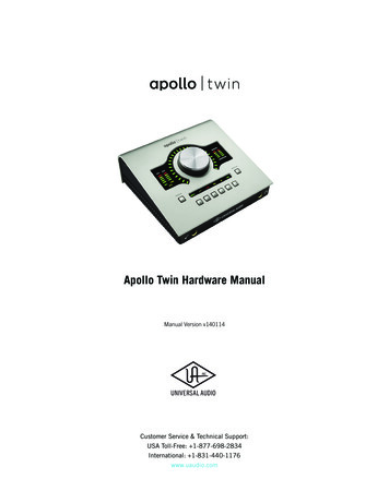
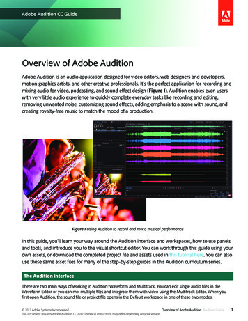
An Overview of Audio System Grounding & Interfacing9/4/2012Example of Wire Impedance vs FrequencyInductance Causes Impedance toRise with Frequency½” Solid RodBill Whitlock, 9/4/2012Overview of Audio System Grounding & Interfacing15At higher frequencies, where inductance dominates, using thicker wire has virtually noeffect on impedance. At 1 MHz, replacing the #12 wire with a ½” solid copper rod haslittle effect (as noted in the plot).Bill Whitlock15
An Overview of Audio System Grounding & Interfacing9/4/2012AC Magnetic Fields and Magnetic InductionFluctuating fieldsurrounds every wirecarrying AC currentBill Whitlock, 9/4/2012Field induces AC voltage inany nearby conductor(transformer principle)Overview of Audio System Grounding & Interfacing16The principle of magnetic induction per Michael Faraday. He is one of my heroesbecause, although he was scorned by the “math snobs” of his day for not publishingcomplex mathematical expressions of his findings, he made truly fundamentaldiscoveries about the relationship between electricity and magnetism.Bill Whitlock16
An Overview of Audio System Grounding & Interfacing9/4/2012What Does “Ground” Mean Also known as “Earth” in the rest of the worldUtility Power: an actual electrical connection to SOILElectronics: a common return path for various circuits, whether or A FANTASY invented by engineers to simplify their worknot actually connected to soil The “uni-potential” fantasy assumes all ground symbols inschematics are at exactly the same voltageTruth: Real-world conductors have resistance, causing small voltage dropsTruth: Ground circuits most often serve, either intentionally or accidentally,more than one purposeMeaning has become vague, ambiguous, and often quite fancifulBill Whitlock, 9/4/2012Overview of Audio System Grounding & Interfacing17The use of ground symbols in schematic diagrams (actually just a convenience foravoiding more lines in the drawing) lulls us into thinking that they’re all at the samepotential. That’s the essence of the fantasy . but far from the truth. Until roomtemperature super-conductors become a common reality, “grounds” are connected bywires, PCB traces, or sheets of metal – all of which have both resistance andinductance. So much for the fantasy!Bill Whitlock17
An Overview of Audio System Grounding & Interfacing9/4/2012Misguided Strategies Reduce unwanted ground voltage differences by “shorting them out”with massive wires or bus-bars Reduce noise experimentally by finding a “better” or “quieter”ground Skillfully route noise to an earth ground, where it disappearsforever! Is an earth ground for electronic systems really necessary? Thinkabout aircraft electronics .Bill Whitlock, 9/4/2012Overview of Audio System Grounding & Interfacing18Random experimentation with grounding connections is the worst possible way tosolve the problems. Not only is little learned in the process, but the experiment can belengthy . usually ending only when someone says “I can live with that.” The ideathat “mother earth” will simply absorb noise is often called the “sump theory” ofgrounding. And when was the last time you saw an airplane dragging around a groundwire?Bill Whitlock18
An Overview of Audio System Grounding & Interfacing9/4/2012Common Myths Earth ground is the absolute zero-volt reference Ground wires have zero impedance Fact: Many unintentional currents flow in soil and create voltage drops justas in any other resistance – soil is a relatively poor electrical conductorFact: Wires have impedance and cannot make multiple points in a systemhave an identical “zero-volt reference”Noise (voltage) exists on a single wire or at a single point Fact: Voltages can exist only between two pointsAll voltages are relative or differentialVoltmeters have two probes .Always ask “Voltage with respect to what?”Bill Whitlock, 9/4/2012Overview of Audio System Grounding & Interfacing19Note that voltmeters invariably have two probes! All voltage readings are differential. even between two “ground” points. And you don’t put one of the probes in yourpocket when you take readings.Bill Whitlock19
An Overview of Audio System Grounding & Interfacing9/4/2012Connections Creating Soil Currents Grounds at utility powerpoles and towers Buried metal pipes(water, gas, waste) Ground electrodes atbuildings Ground is tied to neutralat each location shown Voltage drop ofneutral wires appliedto soil Forms complex networkof soil currentsBill Whitlock, 9/4/2012Overview of Audio System Grounding & Interfacing20Gas and water pipes are required by National Electrical Code (hereinafter referredto as NEC) to be connected to electrical power feeding the building . making the soiland/or the pipes a pathway for currents that flow from building to building. We’ll showa slide about that toward the end of the class.Bill Whitlock20
An Overview of Audio System Grounding & Interfacing9/4/2012AC PowerDistributionNEXT SLIDECourtesy of ONCORBill Whitlock, 9/4/2012Overview of Audio System Grounding & Interfacing21Gas and water pipes are required by NEC to be connected to electrical power feedingthe building . making the soil and/or the pipes a pathway for currents that flow frombuilding to building. We’ll show a slide about that toward the end of the class.Bill Whitlock21
An Overview of Audio System Grounding & Interfacing9/4/2012Delivery of Utility AC Power4,800 V“Feeder”Transformer120 VAC240 V “Split“Split-SingleSingle-Phase”Bill Whitlock, 9/4/2012Overview of Audio System Grounding & Interfacing22Normal residential utility power in North America is properly referred to as splitsingle-phase power.Bill Whitlock22
An Overview of Audio System Grounding & Interfacing9/4/2012The 3-wire System NEC requires 120-volt AC premises power distribution using a 3wire system (since about 1960) LINE (black) and NEUTRAL (white) are intended to carry LOADcurrent, typically up to 15 or 20 A in branch circuits The “safety” GROUND normally carries no currentNEUTRAL and GROUND are bonded only at the main panelNEC PROHIBITS NEUTRAL TO GROUNDCONNECTIONS ANYWHERE ELSENEUTRAL BUSN-G BOND LINKBill Whitlock, 9/4/2012Overview of Audio System Grounding & Interfacing23When new sub-panels are installed, a frequent electrician mistake is connecting the NG bond. This will be discussed later .Bill Whitlock23
An Overview of Audio System Grounding & Interfacing9/4/2012Normal Current in Branch Circuit“LOAD”“SOURCE”** For clarity, meter and other “phase” not shownBill Whitlock, 9/4/2012Overview of Audio System Grounding & Interfacing24None of the load current flows in either safety ground or earth ground. Allload current flows back to its source, which is the utility company’stransformer! Remember, current always flows back to the voltage source,whether through an intentional or unintentional path. Electrons don’t care. they don’t read schematics!Bill Whitlock24
An Overview of Audio System Grounding & Interfacing9/4/2012Grounding for Life Safety Exposed conductive parts (including signal connectors) canbecome “energized” at 120 volts if the equipment developscertain internal defects Insulation is used in power transformers, switches, motors andother internal parts to keep the electricity where it belongs Insulation can and does fail, effectively connecting “live” powerto exposed metal – this is called a FAULT Without equipment safety grounding, people can be seriouslyshocked or electrocuted!Bill Whitlock, 9/4/2012Overview of Audio System Grounding & Interfacing25It’s extremely important to understand the intent of the safety groundsystem!Bill Whitlock25
An Overview of Audio System Grounding & Interfacing9/4/2012Fault Current Trips Breaker Grounding wire in a power cord connects equipment’s exposedmetal to safety ground via 3-prong plug Outlet safety ground returns via green wire or metallic conduit toneutral at main panel Low-impedance connection causes high fault current, which tripsbreaker quickly! Typical fault currents range from 150 A to over 1,000 ASafety grounding must return to NEUTRAL – THE EARTHGROUND CONNECTION IS IRRELEVANT!Bill Whitlock, 9/4/2012Overview of Audio System Grounding & Interfacing26The impedance of earth ground is far too high to cause enough circuit current to trip acircuit breaker.Bill Whitlock26
An Overview of Audio System Grounding & Interfacing9/4/2012FAULT Current Trips Circuit BreakerNOT INVOLVEDBill Whitlock, 9/4/2012Fault currents rangefrom 150 A to 1,000 ATrip times range fromunder 10 ms to 2.5 sOverview of Audio System Grounding & Interfacing27The quoted range of fault currents and trip times is based on a UL study (circa 20032005) of over 1,000 residential 15A and 20A outlets.Bill Whitlock27
An Overview of Audio System Grounding & Interfacing9/4/2012Earth Ground is for LIGHTNING Power lines are frequent targets of lightning Power distribution lines are grounded at intervalsBefore NEC required grounding of power lines, they often guidedlightning strikes directly into buildings!Ground rod impedance is low enough to control lightningNEC requires protection of every line that penetrates abuildingBill Whitlock, 9/4/2012Overview of Audio System Grounding & Interfacing28Lightning involves voltages in the hundreds of millions and currents ranging from5,000 to 150,000 amps (an average strike is about 20,000 amps), briefly unleashingincredible amounts of power. Neighborhood distribution power lines are typicallygrounded at least every 1,500 feet.Bill Whitlock28
An Overview of Audio System Grounding & Interfacing9/4/2012Earth Ground Rod is Useless for Fault CurrentsCircuit Breaker Will NOT Trip!YIKES!HIGH IMPEDANCEBill Whitlock, 9/4/2012Overview of Audio System Grounding & Interfacing29Its connection to earth is not what makes “safety ground” safe . its theconnection to neutral. The impedance of the soil between the ground rodscould be 25 ohms, causing less than 5 A to flow through the circuit breaker.The chassis of the defective equipment would remain at nearly 120 volts – alethal shock hazard. A few years ago, the author attended a product trainingsession for a maker of power conditioners where the “engineer” actuallyadvocated this technique to provide “quiet ground” to an audio listening room!He was subsequently barred from instructing at that trade show – after Ireminded them of their legal liability.Bill Whitlock29
An Overview of Audio System Grounding & Interfacing9/4/2012NEC Grounding Rules During lightning events, thousands of volts can be induced betweenseparate rods Can cause serious damage to any equipment that bridges themTelephone lines per NEC Article 800 Telco NIU protector and its ground connection must be as close aspracticable to point of entry Use insulated, listed wire no smaller than #14 AWG Wiring should be as straight as possible, using gentle curves rather thansharp bends, and physically protected (PVC conduit is preferred)Bond to main power grounding electrode if within 20 feetIf not, use separate 5-foot ground rod and bond to utility power groundwith #6 AWG or larger wireCATV has similar, but not identical, rules (only summarized here)Bill Whitlock, 9/4/2012Overview of Audio System Grounding & Interfacing30Soil has relatively high impedance, allowing very large voltages to develop during evena modest lightning strike to one of them. PVC conduit is preferred because steel wouldincrease the inductance of the wire within, raising its impedance. The #6 bond wirehelps protect against power lines that fall onto telephone lines (due to an autoaccident, for example) by completing a path back to the utility power neutral. Sharpbends in the wire raise its inductance, therefore making it less likely to contain thestrike energy . it may jump out of the wire at the bend and strike something (orsomeone) nearby.Bill Whitlock30
An Overview of Audio System Grounding & Interfacing9/4/2012The “Conduit Transformer” This finally explains what drives 99% of all ground loops! Load current in line and neutral produces opposing magnetic fieldssince instantaneous current flow is in opposite directions Imperfect cancellation magnetically induces voltage over thelength of the nearby safety ground conductor Strongly affected by geometry and proximity of wiresHighest voltages with randomly positioned wires in conduitLower voltages with uniform geometry of Romex Voltage is directly proportional to load current, wire length, andrate of change in current or I/ t Mechanism favors high-frequency harmonics of 60 HzFor constant current in L and N, induced voltage rises at 6 dB/octaveBill Whitlock, 9/4/2012Overview of Audio System Grounding & Interfacing31The favoring of higher harmonics of 60 Hz is why we usually hear “buzz” more oftenthan the more fundamental 60 Hz “hum” and why light dimmers have such a horriblereputation for “causing” noise problems.Bill Whitlock31
An Overview of Audio System Grounding & Interfacing9/4/2012Magnetic Fields in Romex Current in L and N are equal but flow in opposite directionsL NSafety Ground “Sees”Zero Magnetic Field atExact Midpoint(cross-section view)Instantaneous L and N currents areflowing into page and out of pageBill Whitlock, 9/4/2012Overview of Audio System Grounding & Interfacing32There is a magnetic “null zone” exactly midway between line conductorsBill Whitlock32
An Overview of Audio System Grounding & Interfacing9/4/2012The “Conduit Transformer”Wires randomly positioned in conduitproduce the worst possible results!Bill Whitlock, 9/4/2012Overview of Audio System Grounding & Interfacing33The “elephant” that’s been in the room for years but, until recently,unrecognized as THE major driving force behind ground loops! This author,and my co-author Jamie Fox, presented an AES paper on this subject in November2010.Bill Whitlock33
An Overview of Audio System Grounding & Interfacing9/4/2012How the Tests Were PerformedBill Whitlock, 9/4/2012Overview of Audio System Grounding & Interfacing34Excerpt from “Ground Loops: The Rest of the Story” by Bill Whitlock and Jamie Fox, apaper presented 5 Nov 2010 at the AES 129th convention in San Francisco. Availablefrom AES as preprint #8234.Bill Whitlock34
An Overview of Audio System Grounding & Interfacing9/4/2012ResultsBill Whitlock, 9/4/2012Overview of Audio System Grounding & Interfacing35Excerpt from AES paper Ground Loops: The Rest of the Story by Bill Whitlock andJamie Fox, presented 5 Nov 2010 at the 129th AES convention in San Francisco.Available from AES as preprint #8234.Bill Whitlock35
An Overview of Audio System Grounding & Interfacing9/4/2012AC Power is Not Just 60 Hz Many loads, especially “brute force” electronic power supplies,draw current in pulses only at the peaks of the voltage during eachcycle “Power Factor Corrected” or PFC power supplies alleviate this problem120 VAC waveform distortion is typically 2% to 6% THDHigh harmonics are created by sudden current changes Typical low-cost light dimmers have a current risetime of about 5 µs,producing strong harmonics to at least 70 kHz! The conduit transformer favors those harmonics and couples them intosafety ground wiringBill Whitlock, 9/4/2012Overview of Audio System Grounding & Interfacing36And the most notorious generator of fast current changes is . drum roll .LIGHT DIMMERS!Bill Whitlock36
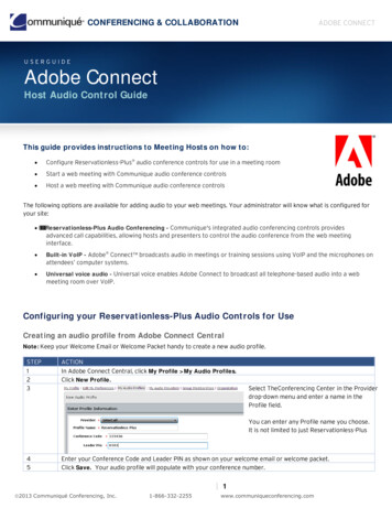
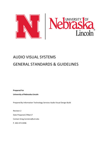
An Overview of Audio System Grounding & Interfacing9/4/2012High-Frequency Noise Sources Phase-control light dimmersFluorescent lampsElectronic power suppliesArcing switches, relays, or motorsPower-line corona dischargeCurrent at 50% brightnessAM radio power line pickupIn the frequency domain, thisrisetime creates very strongharmonics up to 70 kHz.Expanded at 5 µs/divBill Whitlock, 9/4/2012Overview of Audio System Grounding & Interfacing37Now you can see why a light dimmer is at its worst (noise wise) when set for 50%brightness – the line voltage is at maximum when it “snaps” on (taking only about 5us). This was a Lutron “Skylark” dimmer operating with its full rated load of six 100 Wincandescent bulbs. Scale in upper oscilloscope image is 4 A/div.Bill Whitlock37
An Overview of Audio System Grounding & Interfacing9/4/2012Typical Power-Line SpectrumBill Whitlock, 9/4/2012Overview of Audio System Grounding & Interfacing38An actual spec
An Overview of Audio System Grounding & Interfacing 9/4/2012 Bill Whitlock 2 Bill Whitlock, 9/4/2012 Overview of Audio System Grounding & Interfacing 2 About Bill Whitlock Bill began designing analog electronics for console-maker Quad-Eight in 1972 and subsequently held chief engineer po