Transcription
INTRODUCTION u CODES u ABBREVIATIONS u TABLE OF CONTENTSCode 3Check Electrical 7th EditionBased on the 2014 & 2011 NEC and the 2012 IRC BY DOUGLAS HANSEN & REDWOOD KARDONIllustrations & Layout: Paddy Morrissey 2014 by The Taunton Press, Inc. ISBN 978-1-62113-778-8Code Check is a registered trademark of The Taunton Press, Inc., registered in the U.S. Patent & Trademark Office.Code Check Electrical 7th Edition is a field guide to common codeissues in residential electrical installations. It is based on the 2014National Electrical Code (NEC) with cross references to the 2011NEC and the 2012 International Residential Code (IRC). Before beginningany electrical project, check with your local building department to determine thecode edition used in your area. In addition to a model code, energy codes andutility rules may also apply.Where there is no IRC column in the book, the topic might not be addressed bythe IRC. That is the case for older wiring methods and for photovoltaics. The IRCstates that items not specifically mentioned in it must comply with the NEC, evenwhen the local jurisdiction has adopted the IRC. This applies to issues such asold wiring, outside feeders, and photovoltaics, which are not covered in the IRC.For further information, articles by the Code Check team and why Ben Franklin isfeatured in the book visit: www.codecheck.comHOW TO USE CODE CHECK ELECTRICALBasic Conventions:Most lines in Code Check Electrical provide two code references. The first is the2012 IRC reference, and the second is the 2014 NEC reference. Unless the 2014NEC reference is highlighted as a change, the same rule applied in the 2011 NEC.The following example is from p.3:n Max 6 disconnects to shut off power [3601.7]{230.71}This line states that there can be no more than 6 disconnects to shut off the power,and the rule is found in 3601.7 of the IRC and 230.71 of the NEC.An “EXC” at the end of a line means that an exception—or exceptions—to the rule willfollow in the next line, as in this example from p.9:n Size per service conductor size T6 EXC [3603.4]{250.66} 6 AWG Cu largest size needed if ending at rod [T3603.1]{250.66A}This states that the grounding electrode conductor (GEC) size is based on the sizeof the service conductors, in accordance with Table 6, except that the portion of theGEC that solely serves a ground rod need never be larger than 6 AWG.Text lines ending in OR mean that an alternative rule follows in the next line, as in thisexample from p.18:n Separate 20A circuit for bath receptacles only OR [3703.4] {210.11C3} Dedicated 20A circuit to each bathroom [3703.4X] {210.11C3X}A separate 20-amp circuit must be supplied for no other purpose than the bathroomreceptacles. Alternatively, each bathroom can be supplied with its own 20-amp circuit,and then other outlets in that bathroom (such as lights) could be on the circuit.ABBREVIATIONSA amp(s), amperage, ampsAC air conditioningAC alternating currentAC armored cable, a.k.a. “BX”AFCI arc-fault circuit interrupterAHJ Authority Having JurisdictionAl aluminumAMI in accordance with manufacturer’sinstructionsAWG American Wire GaugeCO carbon monoxideCOM communication wirecu. cubic, as in cu. in.Cu copperDC direct currentEGC equipment grounding conductorEMT electrical metallic tubingENT electrical nonmetallic tubing, a.k.a.“Smurf tubing”EV electric vehicleEXC exception(s)FMC flexible metal conduitft. foot, feetGEC grounding electrode conductorGES grounding electrode systemGFCI ground-fault circuit interrupterGFPE ground-fault protection of equipmenthp horsepowerIMC intermediate metal conduitin. inch(es)IRC International Residential Codekcmil 1,000 circular mil units(conductor size – formerly MCM)L&L listed & labeled, listing & labelinglb. pound(s)LFMC liquidtight flexible metal conduitLFNC liquidtight flexible nonmetallicconduitmanu manufacturer(s)max maximumMC metal-clad cablemin minimumn/a minimumNEC National Electrical CodeNFPA National Fire ProtectionAssociationNM nonmetallic-sheathed (cable)OBC AFCI Outlet Branch Circuit AFCIOCPD overcurrent protection device(breaker or fuse)PV photovoltaicPVC rigid polyvinyl chloride conduitreq require, requiring, requirementreq’d requiredreq’s requiresRMC rigid metal conduitSCCR short circuit current ratingSE service entrance cableSFD single-family dwellingsq. square, as in sq. in.temp temperatureUF underground feeder cableUSE underground service entrancecableTR tamper-resistantV volt(s), such as a 120V circuitVA volt-ampere(s), units of apparentpowerW watt(s), units of true (useful) powerWR weather-resistantTABLE OF CONTENTSCode Changes & Using this Book with Older Codes:n HOW TO USE CODE CHECK ELECTRICAL, ABBREVIATIONS, GLOSSARY 1Significant changes are highlighted by having their code number in a different color,and the code number has a superscript reference to the table on p.31. By lookingfor these differently colored code ciations, you can quickly tell is an item applied inthe 2008 NEC, or if it was new in the 2011 NEC, or if it was new in the 2014 NEC.n SERVICES 2If there is no code change in either the 2012 IRC column or the 2014 NEC column,then that particular item also applied in the 2008 NEC. If there is a change in onlythe 2014 NEC column, then the item did not apply in the 2011 NEC. The followingexample is from p.18:n Min one receptacle each car space [n/a] {210.52G1}37This change is a rule that a garage have a minimum of one receptacle outlet per carspace. It is a new rule in the 2014 NEC, and does not apply to the 2012 IRC orthe 2011 NEC. This change is item 37 in the table on the inside back cover.Because the 2012 IRC electrical section is based on the 2011 NEC, changes in the2011 NEC can also be determined from this book, as in this example from from p.12:n Feed-through conductors OK to pass through panel ifwarning label applied that identifies power source [3907.1]13{312.8}This change requires a warning label when conductors from one panel pass throughanother panel. The means of disconnecting the circuit must be identified. It was newin the 2011 NEC, and is change number 13 in the table on the inside back cover.n WORKING SPACE, SEPARATE BLDGS., UNDERGROUND, TEMPORARY WIRING 4n LOAD CALCULATIONS 6n GROUNDING ELECTRODES, GROUNDING ELECTRODE CONDUCTORS 8n BONDING, EQUIPMENT GROUNDING CONDUCTORS, PANELS 10n PANELS, WIRE BENDING SPACE, MULTIWIRE CIRCUITS 12n AFCIS, GFCIS 14n BRANCH CIRCUITS & OUTLETS, KITCHENS 16n BRANCH CIRCUITS & OUTLETS, BOXES, BOX FILL 18n LIGHTING, SWITCHES, APPLIANCES 20n APPLIANCES. AMPACITY TABLES 22n CABLE SYSTEMS, VOLTAGE DROP 24n RACEWAYS, CONDUIT FILL 26n CONDUIT FILL, OLD WIRING, PHOTOVOLTAICS, GENERATORS 28n EV CHARGING, SWIMMING POOLS & SPAS 30n CODE CHANGES 31
GLOSSARYAccessible: Not permanently concealed or enclosed by building construction. A pieceof equipment can be considered accessible even if tools must be used or otherequipment must be removed to gain access to it.Accessible, readily: Capable of being reached quickly for operation or inspectionwithout actions such as the use of tools or ladders or the need to remove obstacles.1 (This is the first code change, described on p. 31)Approved: Acceptable to the authority having jurisdiction (AHJ). The AHJ will usuallyapprove materials that are listed and labeled.Arc-fault: An electric current propagated through air.Arc-Fault Circuit Interrupter (AFCI): A device intended to provide fire protectionby recognizing arc characteristics and de-energizing the circuit when they aredetected.Authority Having Jurisdiction (AHJ): The building official or persons authorized toact on his or her behalf.Bonded, bonding: Connected to establish continuity and conductivity.Branch circuit: The circuit conductors between the final overcurrent protectiondevice (OCPD) (breaker or fuse) protecting the circuit and the outlet or outlets. Branch circuit, general purpose: Branch circuit that supplies 2 or morereceptacles or outlets for lighting and appliances. Branch circuit, individual: Branch circuit supplying only 1 piece of equipment. Branch circuit, multiwire, residential: Branch circuit consisting of 2 hotconductors having 240V potential between them and a grounded neutralhaving 120V potential to each hot conductor F18. Branch circuit, small appliance: Branch circuit supplying portable householdappliances in kitchens and related rooms.Device: A piece of equipment that carries or controls electrical energy as its primaryfunction, such as a switch, receptacle, or circuit breaker.Equipment grounding conductor (EGC): A wire or conductive path that limits voltage on metal surfaces and provides a path for fault currents F10.Feeders: Conductors supplying panelboards other than service panels.Flexibility after installation: Anticipated movement after initial installation, such asthat caused by motor vibration or equipment repositioning.Ground: The earth.Ground fault: An unintentional connection of a current-carrying conductor to equipment, earth, or conductors that are not normally intended to carry current.Ground-Fault Circuit Interrupter (GFCI): A device to protect against shock hazardsby interrupting current when an imbalance of 6 milliamps or more is detected.Grounded conductor: A current-carrying conductor that is intentionally connected toearth (a neutral).Grounding electrode conductor (GEC): A conductor used to connect the serviceneutral or the equipment to a grounding electrode or to a point on the groundingelectrode system F5–9 .Interrupting rating: The highest current a breaker or fuse can interrupt withoutsustaining damage.Luminaire (formerly lighting fixture): A complete lighting unit including parts toconnect it to the power supply, and possibly parts to protect or distribute the lightsource. A lampholder, such as a porcelain socket, is not itself a luminaire.Neutral conductor: The conductor connected to the neutral point of a system andthat is intended to carry current under normal conditions F15–16.Outlet: The point on a wiring system at which current is taken to supply equipment. Areceptacle or a box for a luminaire (fixture) is an outlet; a switch is not an outlet.Overcurrent: Any current in excess of the rating of equipment or conductor insulation.Overcurrents are produced by overloads, ground faults, or short circuits.Overfusing: A fuse or breaker that has an overload rating greater than allowed for theconductor it is protecting.Overload: Equipment drawing current in excess of the equipment or conductor ratingand in such a manner that damage would occur if it continued for a sufficient lengthof time. Short circuits and ground faults are not overloads.Service: The conductors and equipment providing a connection to the utility F1,F15.Service drop: The overhead conductors supplied by the utility F1.Service equipment: The equipment at which the power conductors entering thebuilding can be switched off to disconnect the premises’ wiring from the utility powersource. A meter can be a part of or separate from the service equipment.Service lateral: Underground conductors from the utility to the service point F3.Short circuit: A direct connection of current-carrying conductors without the interposition of a load, resulting in high levels of current.Short Circuit Current Rating (SCCR): The amount of current that panelboards andswitchboards must be able to carry during a short circuit condition withoutsustaining damage. See “Interrupting rating.”CODES u ABBREVIATIONS u TABLE OF CONTENTS u GLOSSARY1
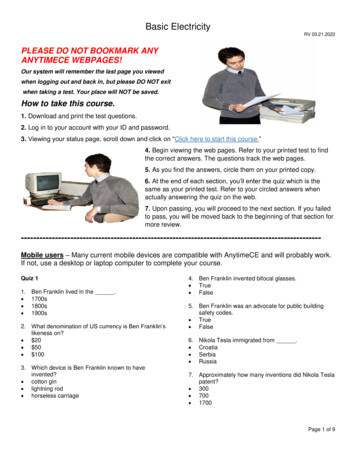
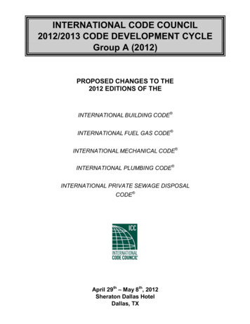
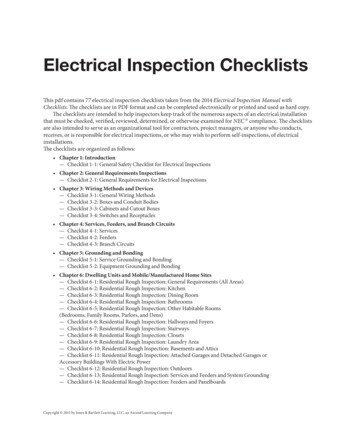
SERVICESFIG. 12Overhead Conductor Clearances18 in.EOverhead Feeder.G8 ft.A10 ft.C18 ft. orper utility.B3 ft.F3 ft.D3 ft.H1 ft.J10 ft.I12 ft.KVertical above Grade F1OVERHEAD SERVICE DROP CLEARANCESService drop conductors typically have no outer jacket for physical protection andno overload protection at their source. They are protected by isolation. The servingutility may have different rules that override the clearance specifications in the code.Check with your local jurisdiction to determine any variations from the standardclearances below. The clearances here also apply to overhead feeders.Vertical above Roof F1Service Drop12 IRC14 NECn 4-in-12 slope: min 8 ft. .A EXC [3604.2.1] 3 ft. OK if roof area guarded or isolated [3604.2.1X5]2n 4-in-12 slope: min 3 ft. .H EXC [3604.2.1X2] 18 in. OK for 4 ft. over eaves .E [3604.2.1X3]n Maintain req’d distance for 3 ft. past roof edge EXC [3604.2.1] Edge clearance above roof is not req’d where overheadconductors attach to side of building .G AX3}{230.24A}{230.24AX4}Communicationswire12 IRC14 NEC10 ft. above final grade to lowest point of drip loop [3604.2.2]Area accessible only to pedestrians: 10 ft. .I [3604.2.2]General above grade & driveways: 12 ft. .K [3604.2.2]Above roads or parking areas subjectto truck traffic: 18 ft. .B [3604.2.2]n Any direction from swimming pool water: 221/2 ft. [4203.6]{230.24B1}{230.24B1}{230.24B2}nnnnOpenings & Communication Wires F212 IRC{230.24B4}{680.8A}14 NECn Vertical above decks & balconies: 10 ft. .C [n/a]{230.9B}n From side of area above decks & balconies: 3 ft. .D [3604.1]{230.9A}n Below or to sides of openable window: 3 ft. .F [3604.1]{230.9A}n Communications wire min 12 in. to parallel power wires .J [n/a] {800.44A4}The clearances from windows & doors apply to open conductors & not to conductors contained inside a raceway or a cable with an overall outer jacket. The codesdo not have a requirement for min. clearance of open conductors above a window.Check to see if your local utility has a requirement.
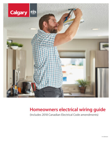
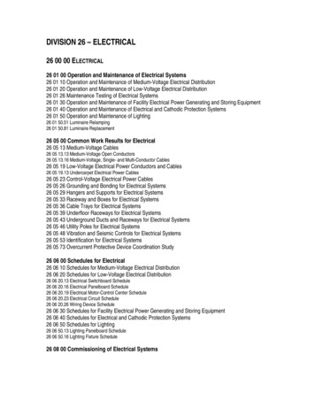
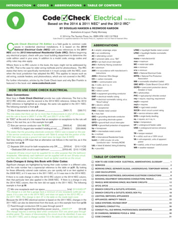
FIG. 17Multiwire CircuitsWire BendingSpace(For clarity, neutrals & EGCs not shown)BDimension T8B from panel wall to lugdetermines max conductor sizeBThe conductors from this breakerare allowed T8A size becausethey exit the side wiring space toan adjacent gutter that has T8Bspace. The adjacent gutter spaceis measured from the boundaryposts above the main lugs.ABConductors exiting wall oppositeterminals limited to T8B sizeAConductors not exiting wallopposite terminals limited to T8AsizeBTABLE 8AFIG. 18Multiwire Circuits240VCompact Al12 – 8n/a8–61½861½4–3264222½423133131/0 – 2/03½21/03½3/0 – 4/0412/04½2504½1/03/05½300 – 35052/04/06400 – 50063/02506½600 – 70084/030071. When a lug lies at an angle, the distance can be measured along the length of the wire in the directionthat the wire leaves the terminal.2. Compact stranded aluminum conductors do not have as much interstitial space as copper conductors andtherefore the table allows slightly larger sizes for these when making an “S” bend.3. The distance is measured in a straight line from the lug in a direction perpendicular to the panel wall.Neutralpoint120V60W120V.A 300W120V120V300W .B 300W0.83A14 – 100.83An/a2.5A14 – 105ARequiredSpace (in.)32.5A(AWG or kcmil)22.5A(AWG)2ACu Wire Size0.5ARequiredSpace (in.)1Utility Transformer Secondary120VS Bends – Wire enters or leavesB enclosure in wall opposite terminal(AWG or kcmil)Wire SizeStandard electrical services to 1- and 2-family dwellings originate at a utilitytransformer with two ungrounded “hot” conductors and a neutral derived from thecenter of the transformer’s secondary coil, as depicted in F18. The neutral is connected to earth and is referred to as the “grounded” conductor. The neutral limitsthe voltage on either of the hot conductors to 120V to ground. Not only is the service to the house a “3-wire” circuit, but 120V branch circuits are often installed withshared neutrals, and are then known as multiwire circuits. If the neutral is brokenor loose, voltages become erratic, as in F18 .C . TV sets, motors, and computersdon’t do well with fluctuating voltages. Signs of unstable voltage, such as incandescent bulbs growing brighter or dimmer as other loads change, could indicate aloose neutral either at a branch circuit or at the utility.MINIMUM WIRING SPACE OPPOSITE TERMINALSL Bends – Wire not throughwall opposite terminal A14 NECOpen neutralBack wall entry conductorslimited to T8A measured to frontpanel edge & T8B measured tobreaker terminal12 IRCn Hot conductors must originate from opposite poles [3501]{100}n All conductors must originate from same panel [3701.5]{210.4A}n Multiwire neutrals may not feed through devices such as receptacles(pigtail lead from neutral to splice in box) [3406.10.2]{300.13B}n All multiwire circuits req handle tie or single handle [3701.5.1]{210.4B}n All conductors of multiwire circuit must be grouped(wire ties or other means) inside panel EXC F16 [3701.5.2]{210.4D} Cable systems where grouping is obvious F16 [3701.5.2X]{210.4DX} Where conductors have numbered wire markerscorresponding to their circuit numbers [n/a] {210.4DX}15200V60W40V.C 300W.A PROPER CIRCUIT 2 unequal loads are fed by a 3-wire circuit. Theneutral carries the imbalance between the 2 loads.B OVERLOADED NEUTRAL Without voltage potential between the hotconductors, the neutral carries the sum of the loads. In a 3-conductor NMcable, the black & red wires must originate from different poles.C OPEN NEUTRAL Two unequal loads in series across 240V from thetransformer. The load with lowest resistance sees the lower voltage. Voltage at each load depends on other loads and is unstable.PANELS u WIRE BENDING SPACE u MULTIWIRE CIRCUITS13
BRANCH CIRCUITS & OUTLETS u BOXES18BRANCH CIRCUITS & OUTLETS (CONTINUED)Bathrooms (see p. 15 for GFCI req’s)12 IRCBOXES14 NECn Receptacle req’d on wall or partition within 3 ft. of each basinor in side or face of cabinet 12 in. below top of basin [3901.6] {210.52D}34n No face-up receptacle outlets on vanity countertop [3901.6]{406.5E}n Listed countertop-mounted receptacles OK [3901.6]35{210.52D}n No receptacles within or directly over tub or shower [4002.11]{406.9C}n Separate 20A circuit for bath receptacles only OR [3703.4] {210.11C3} Dedicated 20A circuit to each bathroom [3703.4X] {210.11C3X}n Max rating of fixed space heater on general lighting circuit15A circuit: 900W; 20A circuit: 1,200W [3702.5] {210.23A2}Laundry (see p. 15 for GFCI req’s)nnnnn12 IRC14 NECMin 1 20A circuit for laundry receptacles [3703.3]No other outlets on laundry receptacle circuit [3703.3]Receptacle within 6 ft. of intended appliance location [3901.5]Electric dryer min 30A circuit [T3704.2(1)]Electric dryer req’s 4-conductor branch circuit EXC [3908.7] Existing 3-wire circuits allowed to remain in use }{250.140X}Outdoors (see p. 15 for GFCI req’s)12 IRC14 NECn Receptacle readily accessible from grade req’d atfront & rear of dwelling max 61/2 ft. above grade [3901.7] {210.52E1}n Receptacle max 61/2 ft. above walking surface req’d atattached decks & balconies w/ interior access [3901.7]36 {210.52E3}n 15A & 20A nonlocking receptacles in damp or wet locationsreq’d to be listed weather-resistant type [4002.8] {406.9A&B}n Receptacles in outdoor damp location (e.g., protected porch)req weatherproof cover [4002.8]{406.8A}n Wet location 15A & 20A receptacles req in-use covers F30 [4002.9]{406.8B1}Garages & Basements (see p. 15 for GFCI req’s) 12 IRCnnnnn14 NECGarages req min one receptacle [3901.9] {210.52G1}Min one receptacle each car space [n/a] {210.52G1}37No outlets outside garage on same circuit as garage [n/a] {210.52G1}38Min one receptacle each accessory building w/ power [3901.9] {210.52G2}Min one receptacle each unfinished basement area [3901.9] {210.52G3}FIG. 30Boxes must be large enough to prevent crushing & overheating of wire anddevices. Wires must be long enough so splices & connections can be worked onclear of the box opening. Luminaires that are supported from boxes are generallydesigned for connections inside the box, rather than inside the luminaire canopy.Device boxes are threaded for 6–32 screws used to mount switches and receptacles. Lighting outlet boxes provide 8–32 (for luminaires) or 10–24 screws (forlisted paddle fan boxes).GeneralPosition in Walls & CeilingsSupport & Ratingnnnnnnnnnn12 IRCIn-use cover12 IRCLuminaireSupportDevice box3 9/32 in.Outlet coverClosedWith plug14 NECFIG. 32Device SupportAccordion cover14 NECBoxes must be supported [3906.8]{314.23}PVC & EMT not OK for box support [3906.8.5] {314.23E&F}PVC & EMT OK for conduit body support [3906.8.5] {314.23E&F}Luminaires only in boxes designed for luminaires EXC [3905.6]{314.27A} Wall sconces 6 lb. on device boxes with 2 #6 screws [3905.6X] {314.27A1X}Ceiling luminaire boxes req 50 lb. rating F32 [3905.7] {314.27A2}Ceiling luminaires 50 lb. req independent support [3905.7] {314.27A2}Wall luminaire boxes max weight marked if 50 lb. [3905.6] {314.27A1}Paddle fans req L&L paddle fan box [3905.9]{314.27C}Ceiling mounted boxes w/ spare separately switchedungrounded conductors req listing for paddle fan [3905.9]{314.27C}Smoke & CO alarms OK to support on device boxes [3905.9X] {314.27A1}FIG. 31Wet Locations14 NECn Max 1/4 in. setback from noncombustible surface F33 [3906.5]{314.20}n Boxes flush or projecting if combustible surface F33 [3906.5]{314.20}Note: the IRC req’s boxes flush or projecting, not set back, in wood-frame walls.n Listed box extenders OK to correct excess setback [3906.5]{314.20}n Plaster gap max 1/8 in. for flush cover boxes F33 [3906.6]{314.21}Damp LocationsOutdoor Covers12 IRCn Boxes req’d for each outlet, splice or pull point EXC [3905.1]{300.15} Integral enclosures, wireways, & gutters [3905.1.3] {300.15A&E}n Metal boxes must be grounded [3905.2]{314.4}n Box & conduit body covers must remain accessible [3905.11]{314.29}n Boxes must be closed w/cover, faceplate, or luminaire [3906.9]{314.25}n Cover must be attached w/ machine screws thatmatch thread gauge integral to box [n/a]{314.25}39n Wet location boxes req listing for wet locations [3905.12]{314.15}n Damp or wet location boxes must keep out water [3905.12]{314.15}n OK to drill ¼ in. drainage holes in wet location boxes [n/a]{314.15}40Example ofoverfilled18 cu. in. box,see T116-32mountingholesLuminaire mud ring8-32 mounting holesOctagonal box 8-32mounting holesPaddle fans req. 10-32 screws on L&L fan box.
the 2014 NEC column, then the item did not apply in the 2011 NEC. The following example is from p.18: n Min one receptacle each car space 37_ [n/a] n{210.52G1} This change is a rule that a garage have a minimum of one receptacle outlet per car space. It is a new rule in the 2014 NEC, and does no