Transcription
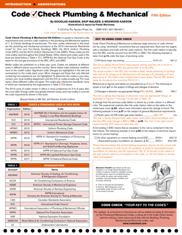
INTRODUCTION u ABBREVIATIONSCode 3Check Plumbing & Mechanical Fifth EditionBy DOUGLAS HANSEN, SKIP WALKER, & REDWOOD KARDONIllustrations & layout by Paddy Morrissey 2019 by The Taunton Press, Inc.ISBN 978-1-631186-947-1Code Check is a trademark of The Taunton Press, Inc., registered in the U.S. Patent & Trademark OfficeCode Check Plumbing & Mechanical 5th Edition is a guide to important coderequirements and common code violations in the plumbing and Mechanical systemsof 1- & 2-family dwellings & townhouses. The main codes referenced in this bookare the plumbing and mechanical provisions of the 2015 International ResidentialCode for One- and Two-Family Dwellings (IRC), the 2015 Uniform PlumbingCode (UPC), and the 2015 Uniform Mechanical Code (UMC). These codes are themost widely used throughout the United States. Other referenced codes used in thebook are listed below in Table 1 (T1). NFPA 54, the National Fuel Gas Code, is thebasis for the fuel gas provisions of the IRC, UPC, and UMC.Model codes are published on a three year cycle. Codes are adopted at differenttimes in different places around the country. Some states make extensive modifications to the model codes. Significant code changes are highlighted in the text andsummarized on the inside back cover. Minor changes and those that only affectednumbering (not substance) are not highlighted. To determine the codes in your area,contact your local building department and the ICC at codes.iccsafe.org. For mosttopics, these different codes will agree. The codes also references standards, manyof which are maintained by the organizations in Table 2 (T2) below.The 2015 cycle of codes remain in effect in most jurisdictions for 3 to 6 years afterthe cover date. Energy codes vary greatly between areas, and may modify or overrulethe code requirements shown in this book.Special thanks to Bill Tott, Jeff Hutcher, & John LaTorraTABLE 1OrganizationCODES & STANDARDS USED IN THIS BOOKEditionCodeASHRAE2016ASHRAE 62.2 Ventilation and Acceptable Indoor AirQuality in Low-Rise Residential BuildingsICC2015International Residential CodeICC2015ISPDC - International Private Sewage Disposal CodeIAPMO2015Uniform Plumbing CodeIAPMO2015Uniform Mechanical CodeNFPA2016NFPA 31 Standard for Installation of Oil-burningEquipmentNFPA2016NFPA 211 Standard for Chimneys, Fireplaces, Vents,and Solid Fuel-Burning AppliancesNFPA2015NFPA 54 National Fuel Gas CodeNFPA2017NFPA 58 Liquified Petroleum Gas CodeNFPA2017NFPA 70 National Electrical CodeTABLE 2ORGANIZATIONSAcronymNameASHRAEAmerican Society of Heating, Air Conditioning,& Refrigeration EngineersACCAAir Conditioning Contractors of AmericaASMEAmerican Society of Mechanical EngineersASSEAmerican Society of Sanitary EngineeringASTMASTM International(formerly the American Society for Testing & Materials)CSACanadian Standards AssociationICCInternational Code CouncilIAPMOInternational Association of Plumbing & Mechanical OfficialsNFPANational Fire Protection AssociationNSFNational Sanitation FoundationSMACNASheet Metal & Air Conditioning Contractors’ National AssociationULUnderwriters LaboratoriesKEY TO USING CODE CHECKCode Check Plumbing & Mechanical condenses large amounts of code information by using “shorthand” conventions that are explained here. Each text line beginswith a checkbox and ends with the code citations. The first code citation is typicallyfrom the IRC, and the second from the UPC or UMC. The following example istaken from p.14 under the topic of plumbing vents:n All fixture traps req venting 3101.2.1901.2This line is stating that all fixture traps require venting, and the rule is found insection 3101.2.1 of the IRC and section 901.2 of the UPC.The actual number in the IRC also includes a letter. Issues pertaining to buildingstart with an R, energy an N, Mechanical an M, fuel gas a G, plumbing a P, andelecrical an E. The letters were omitted here to save space. The full IRC sectionname for the above line would be P3101.2.1.References to figures and tables are preceded by an F or a T. The following example is from p.7 on the subject of fittings and changes of direction:n Changes in direction req appropriate fittings F11–14,T10 3005.1706.1This line is stating that changes of directions must use appropriate fittings, asillustrated in Figures 11 through 14 and also in Table 10.A change from the previous code edition is shown by a code citation in a differentcolor. The superscript endnote after the code citation refers to the table on theinside back cover (p.49), where more information about the change is found. Thefollowing example is from p.27 on the subject of general Mechanical requirements:n Plastic pans not OK under gas water heaters 2801.628n/aThis line is saying that gas-fired water heater catch pans cannot be plastic, andthat this IRC code change is #28 in T49 on p.49. The “n/a” in the right columnmeans that the UPC does not have this rule.A line ending in EXC means that an exception to the rule is contained in the linethat follows. The following example is from p.36 on the subject of electrical requirements for central heating:n No other equipment on central heating circuit EXC 3703.1 Associated pumps, humidifiers, air cleaners, & AC 3703.1422.12422.12XThese lines are stating that central heating equipment requires its own circuit withno other equipment on that circuit. An exception is made for associated pumps,humidifiers, air cleaners, and AC equipment. The “X” at the end of the citation inthe right column refers to an exception in the code, i.e., the full citation is section“422.12 Exception”.Benjamin Franklin was chosen as the maincharacter in our Code Check illustrations for anumber of reasons. Franklin’s insatiable curiosity,scientific genius, and civic-mindedness drovehim to study fire safety, safe exiting, publicsanitation, improved heating methods, andof course, electricity.In 1752, he brought the first bathtubto America. After designing a morecomfortable model, he took it with himon his travels to Europe.CODE CHECK “YOUR KEY TO THE CODES.”For updates & corrections to this book as well as additional tables & informationon the Plumbing & Mechanical Codes, a listing all of the Code Check books,seminar training, online resources & help with the Building, Plumbing,Mechanical and Electrical codes, visit:www.codecheck.com
TABLE OF CONTENTS2TABLE OF CONTENTSGENERAL RULES FOR ALL PIPING 4General Rules & Materials 4Pipe Support 4Pipe Protection in Framing 4TRENCHES & PIPE PROTECTION 5Piping in Concrete or Masonry 5Trenching, Backfilling, & Piping in Common Trench 5DRAINAGE 6Building Drain & Building Sewer 6Size 7Fittings & Changes of Direction 7-8CLEANOUTS 9WASTE STACKS & VENTS 10FIXTURES BELOW MANHOLE COVER OR SEWER 10-11Backwater Valves 10Fixtures below Sewer 11ON-SITE DISPOSAL SYSTEMS 11TRAPS & TAILPIECES 12-13Traps 12Fixture Tailpieces 12Trap Arms (Fixture Drains) 13VENTS 14-15Vents 14Size 14Vertical Wet Venting 15Common Vent 15Horizontal Wet Venting 15SPECIAL VENTING SYSTEMS 16Island Sinks 16Combination Waste & Vent 16VENT TERMINATION 16AIR ADMITTANCE VALVES 17WATER SUPPLY & DISTRIBUTION 17Water Supply – General 17Materials 17CROSS-CONNECTION CONTROL 18JOINTS & VALVES 19Joints & Connections 19Prohibited Joints 19Required Valves 19PRESSURE REGULATORS 18WATER SUPPLY SIZING 20-21Water Service Size 20PEX Tubing & Manifolds 20-21Trunk & Branch Sizing Methods 21GAS PIPING 22-23Metallic Pipe Joints & Fittings 22Underground 22Gas Piping in or Below Slab 22GAS PIPING (Continued) 22-23Protection & Installation 23Piping Support 23Valves, Shutoffs & Appliance Connections 23Electrical 23Drips & Sediment Traps 23CORRUGATED STAINLESS STEEL TUBING (CSST) 23CSST – Typical Manufacturer Recommendations 23Bonding 23Medium Pressure (MP) Regulators 23GAS PIPE & TUBING SIZE 24-25PROPANE (LP GAS) 25Tank Valves & Regulators 25Horizontal ASME Tanks 25Piping & Tubing Systems 25WATER HEATERS 26-27Water Heaters – General Rules 26Special Locations 26Access & Working Space 26Tankless (On Demand) Water Heaters 27Temperature & Pressure Relief Valves 27TPRV Drain Piping 27Required Pans & Drain 27BOILERS & HYDRONICS 28Steam & Hot-Water Boilers 28Dual Purpose Water Heaters 28Exposed Piping 28Hydronic Piping - General 28Embedded Piping (Radiant Heating) 28FIXTURES 29Fixtures – General 29Kitchen Sinks & Dishwashers 29KITCHEN APPLIANCES 29Ranges & Range Hoods 29BATHROOMS 30Toilets & Bidets 30Tubs & Whirlpools 30Showers 30Shower Pan & Liner 30LAUNDRY 31Clothes Washers & Laundry Sinks 31IRC Electric or UMC Electric or Gas Dryers 31IRC Gas Clothes Dryer Exhaust 31Clothes Dryer Electrical 31OIL TANKS & PIPING 32Tanks – Outside, Inside & Abandonded 32Fill & Vent Piping 32Piping & Tubing to Appliances 32OIL-FIRED APPLIANCES 32-33
COMBUSTION AIR FOR OIL-FIRED APPLIANCES 33OIL-FIRED APPLIANCE CHIMNEYS & VENTS 33Chimneys & Type L Vents 33Chimney Connectors 33VENTILATION & EXHAUST SYSTEMS 34Whole Building Ventilation 34Local Exhaust 34Additional Air Quality Requirements 34Heat Recovery Ventilators (HRV) 34Ceiling Suspended Paddle Fans 34Bathroom Exhaust & Ventilation 34GENERAL MECHANICAL SYSTEM REQUIREMENTS 35Permits & Interpretations 35Listing & Labeling 35Appliance Maintenance 35Minimum Heating Requirements 35APPLIANCE LOCATION, ACCESS & ANCHORAGE 35ELECTRIC HEAT 35Central Electric Heat 35Baseboard Heaters 35Electric Radiant Heat Systems 35Electric Duct Heaters 35Embedded Heating Cables in Concrete or Slurry Floors 35FORCED AIR FURNACES 36Location & Clearances 36Electrical Requirements 36Appliances Under Floors 36Garage 36Equipment on Roofs 36Appliances in Attics 36AIR-CONDITIONING & HEAT PUMPS 37Heat Pumps (HPs) & Air-Conditioning (AC) 37Window & Through-Wall AC Units 37EVAPORATIVE (SWAMP) COOLERS 37CONDENSATE DISPOSAL 38Drain Piping 38Primary Concensate Lines 38Secondary Containment 38Condensate Pumps 38High-Efficiency Appliances (Category IV) 38DUCTS 39Duct Installation 39SMACNA Standards 39Return Air 39Insulation in Unconditioned Space 39GAS APLIANCE COMBUSTION AIR (C.A.) 40Mechanically Supplied Combustion Air 40Openings 40Ducts 40Single-Opening & Two-Opening Methods 40Attic & Crawl-Space Sources 40Indoor Air Source 40GAS APPLIANCE VENTS 41Gas Vents – General 41Single Wall Vents 41Chimneys 41VENT CONNECTORS 41Single Wall Connectors for Category I Appliances 41Type B Double-Wall Connectors 41VENT SIZES 42Vent Size (Appliances with Draft Hoods) 42Vent Size Using GMA Vent Tables 42Examples of GAMA Vent Tables 42Multiple Appliances Vented in Common 42GAS VENT TERMINATIONS 43Vent Terminations – General 43Condensing Appliance Forced Vents (Cat. IV) 43GAS FLOOR FURNACES 44GAS WALL FURNACES 44ROOM HEATERS 45Vented Room Heaters 45Unvented Heaters 45DIRECT-VENT HEATING APPLIANCES 45Direct-Vent Gas Wall Heaters 45Direct Vent Termination 45Direct-Vent Gas Fireplaces 45GAS APPLIANCES IN FIREPLACES 45Decorative Appliances (log-sets) in Fireplaces 45Vented Decorative Gas Fireplaces 45Vented Gas Fireplace Heaters 45Log Lighters 45FREESTANDING FIREPLACE STOVES (SOLID FUEL) 46Fireplace Stoves & Solid-Fuel Room Heaters 46Connectors 46Connection to Masonry Fireplaces (Stoves & Fireplace 46CLEARANCE REDUCTION SYSTEMS 47FIREPLACES & CHIMNEYS 47Fireplace & Chimney Construction 47SDC D 0, D 1 & D 2 Reinforcement 47Flues 47Masonry Fireplaces 47Factory-Built Fireplaces & Chimneys 47Exterior Air Supply (Masonry or Factory-Built 47RECOMMENDED INSPECTIONS OF EXISTING CHIMNEYS 47INSPECTIONS 48Water Supply 48DWV Systems 48Hydronics 48Fuel Gas 48STRUCTURAL 48Pipe Protection in Framing 48Structural Modifications & Fireblocking 48Notches in Joists & Rafters 48Stud Notching & Boring 48CODE CHANGES TABLE 49TABLE OF CONTENTS3
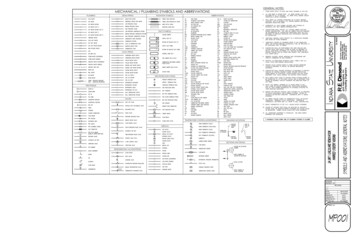
DRAINAGE (CONTINUED)Drain, waste and vent (DWV) pipe sizes are determined by the number of drainage fixture unitsthat each pipe carries. Begin by drawing an isometric diagram of all the fixtures, and assign eachthe appropriate number of drainage fixture units from T6. Start at the highest point of the systemand work down to the building drain, sizing each pipe per T8 or T9 for the number of DFUs.Drain Pipe Size15 IRC15 UPCn Size piping per DFU loads T6–T9 3005.4n Branches & building drain max load per T7 & T8 3005.4.1&2n Kitchen, bath, & laundry group DFUs can be per T9 T3004.1703.1703.2n/aTABLE 6DFUs & TRAP SIZE u IRC T3004.1 & T3201.7 UPC T702.1IRCFixtureBar SinkUPCDFUsTrap SizeDFUsTrap Size11¼11½Bathtub (w/ or w/o shower)21½21½Bidet11¼11¼Bidet (1½ in. outlet)11½21½CW Standpipe2232Dishwasher (independent drain)21½21½AFloor drain0202KS21½21½ALT21½21½BBuilding drain branches are the horizontal pipes that connect directly to the building drain. Theycan be carrying the drainage from multiple branch drains which are less likely to all be used atthe same time. Therefore, the IRC allows these drains, and the building drain and building sewer,a larger number of DFUs than for the upstream branch drains of the same pipe size. The UPCdoes not have a corresponding system other than in an engineered design approved by the AHJ.IRC MAX DFUs ON BUILDING DRAIN, BUILDING DRAINBRANCHES, & BUILDING SEWER u IRC T3005.4.2TABLE 8Slope (in. per ft.)Pipe size (in.)1 8¼½1½n/aNote ANote A2Bn/a21272½Bn/a2431A33642504180216250A. 1½ in. horizontal branches to building drains limited to 1 pumped fixture (included food waste grinder) or2 non-pumped fixtures.B. Drains 3 in. may not receive discharge from water closets.Kitchen, bath, and laundry groups can be sized using T9, which allows a smaller number ofDFUs than would be calculated if each individual fixture drain were assigned values from T6.UPC appendix C (Alternate Plumbing Systems) provides a similar system and requires approvalby the AHJ.TABLE 9KITCHEN, BATH, & LAUNDRY GROUPS u IRC T3004.1Lavatory11¼11¼GroupDescriptionDFUsSingle head shower stall21½22Full Bath1.6 GPF WC, lavy, tub w/ or w/o shower5AAdditional shower heads2Note C12Half Bath1.6 GPF WC lavy4AWater Closet (toilet) 1.6 GPF3n/a3n/aWater Closet (toilet) 1.6 GPF4n/a4n/aLaundryCW standpipe laundry tray3A. UPC: Min. 2 in. drainB. W/ or w/o DW or food waste grinder.C. The IRC bases the trap size on the flow rate. 5.7 gpm & 12.3 gpm 2 in., 25.8 gpm 3 in.11/4 in.11/2 in.2 in.21/2 in.3 in.4 Pipe sizeA. Based on ¼ in./ft. slopeSeparate DW & sink21 full bath 1 half bath7BA. Add 1 DFU if WC is 1.6 gal. per flush.B. For each additional bath beyond 1½ baths, add 1 DFU per half bath, 2 DFUs per full bath.BRANCH DRAIN MAX DFUSIRC T3005.4.1 & UPC T703.2TABLE 7KitchenMultiple Bath GroupsFittings & Changes of Direction15 IRCn Changes in direction req appropriate fittings F11–14,T10 3005.1n Use double sanitary tees or equivalent (back-to-back fixture fitting)for 2 fixture inlets at same level F11 3005.1.1n Double sanitary tee barrel min 2 sizes larger than inlets F11 n/an No horizontal-horizontal fittings within 10 pipe diametersdownstream of stack base or horizontal offset 3005.5n Sanitary tee horizontal to vertical only, not on “back” F12 3005.1DRAIN MATERIALS u DRAIN & VENT SIZE15 UPC706.1706.2706.2n/a706.17
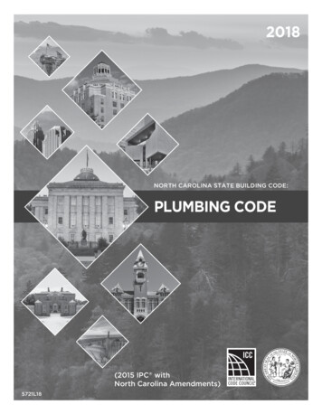
DRAINAGE FITTINGS & CONNECTIONSTABLE 10APPLICATION OF FITTINGS u IRC T3005.1 & UPC 706Fitting1 16Horizontal toVerticalVertical toHorizontalHorizontal toHorizontal4bend441 8bend4441 6bend44IRC 4 UPC ؼ bend4IRCA UPC ØIRCA UPC ØShort sweep(cast iron)44B4ALong sweep444Sanitary tee4 C,DØØWye444Combo wye &1 8 bend444A. IRC max. 2 in. diameter.B. IRC fixture drain max 2 in. diameter, fitting min. 3 in. diameter.C. Double sanitary tees not to receive discharge from pumped waste or from WCs unless min. 18 in.between WC and fitting.D. Double sanitary tees in UPC must have barrel 2 pipes sizes larger than inlets.FIG. 13DWV Fittings60 1 6WyebendDrainsEntering atSame LevelDouble san teeA back-to-back fixture fitting should be used for fixtures or trap arms entering at thesame level. The IRC allows a double sanitary tee to be used for this purpose wherethey are similar fixtures and both drains are the same size. The UPC only allows itfor branch drains entering at the same level and into a barrel that is a min of two pipesizes larger than the inlets.1 4 bend1 4 bendventIRC allows horizontal-to-horizontal 1/4bend up to 2 in. diameter.Long sweepFIG. 12Sanitary TeesNot OK onbackVIOLATION!OK only forhorizontal to verticalbend90 Application of FittingsBack-to-back fittingbend22.5 1 16Sanitary tee90 Combo45 1 8FIG. 14FIG. 118Combo or Wye & 1/8bendLong sweep
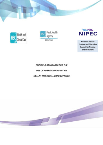
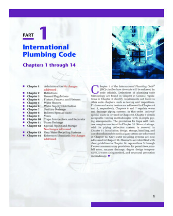
FIG. 15CLEANOUTSCleanouts are necessary for clearing drain obstructions and for inspecting the building sewerwith a sewer camera. Each code has restrictions on cleanouts in crawlspaces. The UPCrequires that underfloor cleanouts be no further than 5 ft. from the crawl access opening. TheIRC allows cleanouts in crawlspaces only where the travel path is a minimum of 24 inches high.When those conditions cannot be met, the cleanouts must be extended to the exterior.15 UPCn COs liquid & gas tight 707.3n Plugs brass or plastic w/ raised head or countersunk slot 707.1n Min plug size for 2 in. pipe 1½ in., 2½ in. or 3 in. pipe 2½ in., 4 in. pipe 3½ in. 707.10n Req’d at upper terminal of all horizontal runs F15 EXC 707.4 Horizontal runs 5 ft. (unless serving sinks or urinals) 707.4X1 Horizontal pipes 72 from vertical (1 5 bend) 707.4X2 Pipes above lowest floor of building 707.4X3 No upper terminal CO req’d if 2-way CO at junction of buildingdrain and building sewer F10 707.4X4n Req’d every 100 ft. length or fraction of developed length 707.4n Req’d for runs w/ aggregate change of direction 135 F16 707.4n Trap arm bends 90 do not req CO 707.14n Takeoff above flow line unless wye branch or end of line F17 707.5n Clearance in front of CO min 24 in. exc 2 in. pipe 18 in. OK 707.910n Underfloor CO must extend above finished floor or outsid
Code Check Plumbing & Mechanical 5th Edition is a guide to important code requirements and common code violations in the plumbing and Mechanical systems of 1- & 2-family dwellings & townhouses. The main codes referenced in this book are the plumbing and me