Transcription
Verilog HDLA guide to Digital Designand SynthesisSamir PalnitkarSunSoft Press1996
PART 1 BASIC VERILOG TOPICS1Overview of Digital Design with Verilog HDL2Hierarchical Modeling Concepts3Basic Concepts4Modules and Ports5Gate-Level Modeling6Dataflow Modeling7Behavioral Modeling8Tasks and Functions9Useful Modeling TechniquesPART 2 Advance Verilog Topics10 Timing and Delays11 Switch- Level Modeling12 User-Defined Primitives13 Programming Language Interface14 Logic Synthesis with Verilog HDLPART3 APPENDICESAStrength Modeling and Advanced Net DefinitionsBList of PLI RountinesCList of Keywords, System Tasks, and Compiler DirectivesDFormal Syntax DefinitionEVerilog TidbitsFVerilog 321327343345363367
Part 1 Basic Verilog TopicsOverview of Digital Design with Verilog HDLEvolution of CAD, emergence of HDLs, typical HDL-based design flow, whyVerilog HDL?, trends in HDLs.Hierarchical Modeling ConceptsTop-down and bottom-up design methodology,differences betweenmodules and module instances, parts of a simulation,design block, stimulusblock.Basic ConceptsLexical conventions, data types, system tasks, compiler directives.Modules and PortsModule definition, port declaration, connecting ports, hierarchical namereferencing.Gate-Level ModelingModeling using basic Verilog gate primitives, description of andlor andbuflnot type gates, rise, fall and turn-off delays, min, max, and typicaldelays.Dataflow ModelingContinuous assignments, delay specification,expressions, operators,operands, operator types.Behavioral ModelingStructured procedures, initial and always, blocking'and nonblockingstatements, delay control, event control, conditional statements,multiwaybranching, loops, sequential and parallel blocks.Tasks and FunctionsDifferencesbetween tasks and functions, declaration, invocation.Useful Modeling TechniquesProcedural continuous assignments, overriding parameters, conditionalcompilation and execution, useful system tasks.
Verilog HDL: A Guide to Digital Design and Synthesis
Overview of Digital Designwith Verilog" HDL1s1.1 Evolution of Computer Aided Digital DesignDigital circuit design has evolved rapidly over the last 25 years. The earliestdigital circuits were designed with vacuum tubes and transistors. Integratedcircuits were then invented where logic gates were placed on a single chip. Thefirst integrated circuit (IC) chips were SS1 (Small Scale Integration) chips where thegate count was very small. As technologies became sophisticated, designers wereable to place circuits with hundreds of gates on a chip. These chips were calledMS1 (Medium Scale Integration) chips. With the advent of LSI (Large ScaleIntegration), designers could put thousands of gates on a single chip. At this point,design processes started getting very complicated, and designers felt the need toautomate these processes. Computer Aided Design (CAD)' techniques began toevolve. Chip designers began to use circuit and logic simulation techniques toverify the functionality of building blocks of the order of about 100 transistors.The circuits were still tested on the breadboard, and the layout was done onpaper or by hand on a graphic computer terminal.With the advent of VLSI (Very Large Scale Integration) technology, designers coulddesign single chips with more than 100,000 transistors. Because of the complexityof these circuits, it was not possible to verify these circuits on a breadboard.Computer-aided techniques became critical for verification and design of VLSIdigital circuits. Computer programs to do automatic placement and routing ofcircuit layouts also became popular. The designers were now building gate-leveldigital circuits manually on graphic terminals. They would build small buildingblocks and then derive higher-level blocks from them. This process would1.Technically, the term Computer-Aided Design ( C A D ) tools refers to back-end tools that perform functions relatedto place and route, and layout of the chip. The term Computer-Aided Engineering (CAE) tools refers to tools thatare used for front-end processes such HDL simulation, logic synthesis and timing analysis. However, designersuse the term C A D and C A B interchangeably. For the sake of simplicity, in this book, we will refer to all designtools as C A D tools.
continue until they had built the top-level block. Logic simulators came intoexistence to verify the functionality of these circuits before they were fabricatedon chip.As designs got larger and more complex, logic simulation assumed an importantrole in the design process. Designers could iron out functional bugs in thearchitecture before the chip was designed further.Emergence of HDLsFor a long time, programming languages such as FORTRAN, Pascal, and C werebeing used to describe computer programs that were sequential in nature.Similarly, in the digital design field, designers felt the need for a standardlanguage to describe digital circuits. Thus, Hardware Description Languages (HDLs)came into existence. HDLs allowed the designers to model the concurrency ofprocesses found in hardware elements. Hardware description languages such asVerilog H D L and VHDL became popular. Verilog HDL originated in 1983 atGateway Design Automation. Later, VHDL was developed under contract fromDARPA. Both verilogB and VHDL simulators to simulate large digital circuitsquickly gained acceptance from designers.Even though HDLs were popular for logic verification, designers had to manuallytranslate the HDL-based design into a schematic circuit with interconnectionsbetween gates. The advent of logic synthesis in the late 1980s changed the designmethodology radically. Digital circuits could be described at a register transfer level(RTL) by use of an HDL. Thus, the designer had to specify how the data flowsbetween registers and how the design processes the data. The details of gates andtheir interconnections to implement the circuit were automatically extracted bylogic synthesis tools from the RTL description.Thus, logic synthesis pushed the HDLs into the forefront of digital design.Designers no longer had to manually place gates to build digital circuits. Theycould describe complex circuits at an abstract level in terms of functionality anddata flow by designing those circuits in HDLs. Logic synthesis tools wouldimplement the specified functionality in terms of gates and gate interconnections.HDLs also began to be used for system-level design. HDLs were used forsimulation of system boards, interconnect buses, FPGAs (Field ProgrammableGate Arrays), and PALS (Programmable Array Logic). A common approach is todesign each IC chip, using an HDL, and then verify system functionality viasimulation.Verilog HDL: A Guide to Digital Design and Synthesis
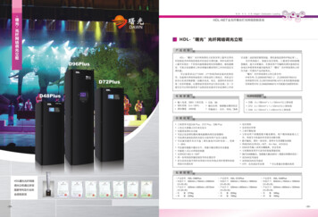
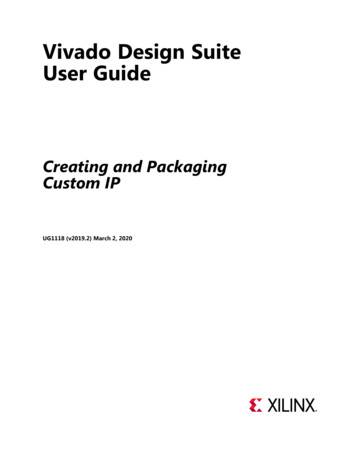
1.3 Typical Design FlowA typical design flow for designing VLSI IC circuits is shown in Figure 1-1.Unshaded blocks show the level of design representation; shaded blocks showprocesses in the design flow.IIBehavioral DescriptiontRTL Description (HDL)(I#ItLogic SynthesisGate-Level NetlistePhysical LayoutlImplementationFigure 1-1Typical Design FlowOverview of Digital Design with Verilog@HDL
The design flow shown in Figure 1-1 is typically used by designers who useHDLs. In any design, specifications are written first. Specifications describeabstractly the functionality, interface, and overall architecture of the digital circuitto be designed. At this point, the architects do not need to think about how theywill implement this circuit. A behavioral description is then created to analyze thedesign in terms of functionality, performance, compliance to standards, and otherhigh-level issues. Behavioral descriptions can be written with HDLs.The behavioral description is manually converted to an RTL description in anHDL. The designer has to describe the data flow that will implement the desireddigital circuit. From this point onward, the design process is done with theassistance of Computer-Aided Design (CAD) tools.Logic synthesis tools convert the RTL description to a gate-level netlist. A gatelevel netlist is a description of the circuit in terms of gates and connectionsbetween them. The gate-level netlist is input to an Automatic Place and Routetool, which creates a layout. The layout is verified and then fabricated on chip.Thus, most digital design activity is concentrated on manually optimizing theRTL description of the circuit. After the RTL description is frozen, CAD tools areavailable to assist the designer in further processes. Designing at RTL level hasshrunk design cycle times from years to a few months. It is also possible to domany design iterations in a short period of time.Behavioral synthesis tools have begun to emerge recently. These tools can createRTL descriptions from a behavioral or algorithmic description of the circuit. Asthese tools mature, digital circuit design will become similar to high-levelcomputer programming. Designers will simply implement the algorithm in anHDL at a very abstract level. CAD tools will help the designer convert thebehavioral description to a final IC chip.It is important to note that although CAD tools are available to automate theprocesses and cut design cycle times, the designer is still the person who controlshow the tool will perform. CAD tools are also susceptible to the "GIGO : GarbageI n Garbage Out" phenomenon. If used improperly, CAD tools will lead toinefficient designs. Thus, the designer still needs to understand the nuances ofdesign methodologies, using CAD tools to obtain an optimized design.1.4 Importance of HDLsHDLs have many advantages compared to traditional schematic-based design.Designs can be described at a very abstract level by use of HDLs. Designerscan write their RTL description without choosing a specific fabricationtechnology. Logic synthesis tools can automatically convert the design toVerilog HDL: A Guide to Digital Design and Synthesis
any fabrication technology. If a new technology emerges, designers do notneed to redesign their circuit. They simply input the RTL description to thelogic synthesis tool and create a new gate-level netlist, using the newfabrication technology. The logic synthesis tool will optimize the circuit inarea and timing for the new technology.By describing designs in HDLs, functional verification of the design can bedone early in the design cycle. Since designers work at the RTL level, theycan optimize and modify the RTL description until it meets the desiredfunctionality. Most design bugs are eliminated at this point. This cuts downdesign cycle time significantly because the probability of hitting a functionalbug at a later time in the gate-level netlist or physical layout is minimized.Designing with HDLs is analogous to computer programming. A textualdescription with comments is an easier way to develop and debug circuits.This also provides a concise representation of the design, compared to gatelevel schematics. Gate-level schematics are almost incomprehensible for verycomplex designs.HDLs are most certainly a trend of the future. With rapidly increasingcomplexities of digital circuits and increasingly sophisticated CAD tools, HDLswill probably be the only method for large digital designs. No digital circuitdesigner can afford to ignore HDL-based design.Popularity of Verilog HDLVerilog HDL has evolved as a standard hardware description language. VerilogHDL offers many useful features for hardware design.Verilog HDL is a general-purpose hardware description language that iseasy to learn and easy to use. It is similar in syntax to the C programminglanguage. Designers with C programming experience will find it easy tolearn Verilog HDL.Verilog HDL allows different levels of abstraction to be mixed in the samemodel. Thus, a designer can define a hardware model in terms of switches,gates, RTL, or behavioral code. Also, a designer needs to learn only onelanguage for stimulus and hierarchical design.Most popular logic synthesis tools support Verilog HDL. This makes it thelanguage of choice for designers.Overview of Digital Design with VerilogBHDL
All fabrication vendors provide Verilog HDL libraries for postlogic synthesissimulation. Thus, designing a chip in Verilog HDL allows the widest choiceof vendors.The Programming Language Interface (PLI) is a powerful feature that allowsthe user to write custom C code to interact with the internal data structuresof Verilog. Designers can customize a Verilog HDL simulator to their needswith the PLI.1.6 Trends in HDLsThe speed and complexity of digital circuits has increased rapidly. Designers haveresponded by designing at higher levels of abstraction. Designers have to thinkonly in terms of functionality. CAD tools take care of the implementation details.With designer assistance, CAD tools have become sophisticated enough to do aclose-to-optimum implementation.The most popular trend currently is to design in HDL at an RTL level, becauselogic synthesis tools can create gate-level netlists from RTL level design.Behavioral synthesis has recently emerged. As these tools improve, designers willbe able to design directly in terms of algorithms and the behavior of the circuit,and then use CAD tools to do the translation and optimization in each phase ofthe design. Behavioral modeling will be used more and more as behavioralsynthesis matures. Until then, RTL design will remain very popular.Formal verification techniques are also appearing on the horizon. Formalverification applies formal mathematical techniques to verify the correctness ofVerilog HDL descriptions and to establish equivalency between RTL and gatelevel netlists. However, the need to describe a design in Verilog HDL will not goaway.For very high speed and timing-critical circuits like microprocessors, the gatelevel netlist provided by logic synthesis tools is not optimal. In such cases,designers often mix gate-level description directly into the RTL description toachieve optimum results. This practice is opposite to the high-level designparadigm, yet it is frequently used for high-speed designs because designers needto squeeze the last bit of timing out of circuits and CAD tools sometimes prove tobe insufficient to achieve the desired results.A trend that is emerging for system-level design is a mixed bottom-upmethodology where the designers use either existing Verilog HDL modules, basicbuilding blocks, or vendor-supplied core blocks to quickly bring up their systemsimulation. This is done to reduce development costs and compress designschedules. For example, consider a system that has a CPU, graphics chip, I/O8Verilog HDL: A Guide to Digital Design and Synthesis
chip, and a system bus. The CPU designers would build the next-generation CPUthemselves at an RTL level, but they would use behavioral models for thegraphics chip and the 1 / 0 chip and would buy a vendor-supplied model for thesystem bus. Thus, the system-level simulation for the CPU could be up andrunning very quickly and long before the RTL descriptions for the graphics chipand the 1 / 0 chip are completed.Overview of Digital Design with VerilogBHDL
Verilog HDL: A Guide to Digital Design and Synthesis
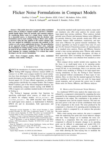
Hierarchical ModelingConceptsBefore we discuss the details of the Verilog language, we must firstunderstand basic hierarchical modeling concepts in digital design. Thedesigner must use a "good" design methodology to do efficient Verilog HDLbased design. In this chapter, we discuss typical design methodologies andillustrate how these concepts are translated to Verilog. A digital simulation ismade up of various components. We talk about the components and theirinterconnections.Learning ObjectivesUnderstand top-down and bottom-up design methodologies for digitaldesign.Explain differences between modules and module instances i*n Verilog.Describe four levels of abstraction-behavioral,switch level-to represent the same module.data flow, gate level, andDescribe components required for the simulation of a digital design. Definea stimulus block and a design block. Explain two methods of applyingstimulus.2.1 Design MethodologiesThere are two basic types of digital design methodologies: a top-down designmethodology and a bottom-up design methodology. In a top-down designmethodology, we define the top-level block and identify the sub-blocks necessaryto build the top-level block. We further subdivide the sub-blocks until we come toleaf cells, which are the cells that cannot further be divided. Figure 2-1 shows thetop-down design process.
Top levelFigure 2-155Top-down Design MethodologyIn a bottom-up design methodology, we first identify the building blocks that areavailable to us. We build bigger cells, using these building blocks. These cells arethen used for higher-level blocks until we build the top-level block in the design.Figure 2-2 shows the bottom-up design process.macrocell 1Figure 2-2macromacromacrocell 4Bottom-up Design MethodologyTypically, a combination of top-down and bottom-up flows is used. Designarchitects define the specifications of the top-level block. Logic designers decidehow the design should be structured by breaking up the functionality into blocksand sub-blocks. At the same time, circuit designers are designing optimizedcircuits for leaf-level cells. They build higher-level cells by using these leaf cells.12Verilog HDL: A Guide to Digital Design and Synthesis
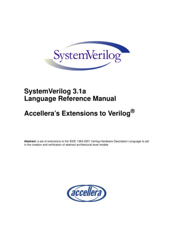
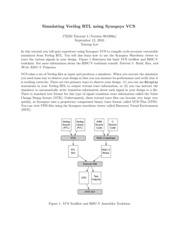
The flow meets at an intermediate point where the switch-level circuit designershave created a library of leaf cells by using switches, and the logic level designershave designed from top-down until all modules are defined in terms of leaf cells.To illustrate these hierarchical modeling concepts, let us consider the design of anegative edge-triggered Cbit ripple carry counter described in Section 2.2,4-bitRipple Carry Counter.2.2 4-bit Ripple Carry CounterRippleCarryCounter-clockIIIOIlIresetFigure 2-3qo- - --ql---- --Cl2----------d'l-lT-FFtffOC)'l%T-FFtffl'l3) T-FFq Ltff2I9T-FFtff3I1IIlIIRipple Carry CounterThe ripple carry counter shown in Figure 2-3 is made up of negative edgetriggered toggle flip-flops (T-FF). Each of the T-FFs can be made up fromnegative edge-triggered D-flipflops (D-FF) and inverters (assuming q-bar outputis not available on the D-FF), as shown in Figure 2-4.Hierarchical Modeling Concepts
resetFigure 2-4T-flipflopThus, the ripple carry counter is built in a hierarchical fashion by using buildingblocks. The diagram for the design hierarchy is shown in Figure 2-5.IRivvle CarrvIhL1InverterFigure 2-5Design HierarchyIn a top-down design methodology, we first have to specify the functionality ofthe ripple carry counter, which is the top-level block. Then, we implement thecounter with T-FFs. We build the T-FFs from the D-FF and an additional invertergate. Thus, we break bigger blocks into smaller building sub-blocks until wedecide that we cannot break up the blocks any further. A bottom-up methodologyflows in the opposite direction. We combine small building blocks and buildVerilogHDL: A Guide to Digital Design and Synthesis
bigger blocks; e.g., we could build D-FF from and and or gates, or we couIdbuild a custom D-FF from transistors. Thus, the bottom-up flow meets the topdown flow at the level of the D-FF.2.3 ModulesWe now relate these hierarchical modeling concepts to Verilog. Verilog providesthe concept of a module. A module is the basic building block in Verilog. Amodule can be an element or a collection of lower-level design blocks. Typically,elements are grouped into modules to provide common functionality that is usedat many places in the design. A module provides the necessary functionality tothe higher-level block through its port interface (inputs and outputs), but hidesthe internal implementation. This allows the designer to modify module internalswithout affecting the rest of the design.In Figure 2-5, ripple carry counter, TFF, D-FF are examples of modules. In Verilog,a module is declared by the keyword module. A corresponding keywordendmodule must appear at the end of the module definition. Each module musthave a module-name, which is the identifier for the module, and amodule-terminal-list, which describes the input and output terminals of themodule.lmodule module-name ( module-terminal-list ) ;i module internals.endmoduleSpecifically, the T-flipflop could be defined as a module as follows:moduleT-FF(q,clock, r e s e t ) ; functionality of T-flipflop endmoduleHierarchical Modeling Concepts15
Verilog is both a behavioral and a structural language. Internals of each modulecan be defined at four levels of abstraction, depending on the needs of the design.The module behaves identically with the external environment irrespective of thelevel of abstraction at which the module is described. The internals of the moduleare hidden from the environment. Thus, the level of abstraction to describe amodule can be changed without any change in the environment. These levels willbe studied in detail in separate chapters later in the book. The levels are definedbelow.Behavioral or algorithmic levelThis is the highest level of abstraction provided by Verilog HDL. A modulecan be implemented in terms of the desired design algorithm withoutconcern for the hardware implementation details. Designing at this level isvery similar to C programming.Dataflow levelAt this level the module is designed by specifying the data flow. Thedesigner is aware of how data flows between hardware registers and howthe data is processed in the design.Gate levelThe module is implemented in terms of logic gates and interconnectionsbetween these gates. Design at this level is similar to describing a design interms of a gate-level logic diagram.Switch levelThis is the lowest level of abstraction provided by Verilog. A module can beimplemented in terms of switches, storage nodes, and the interconnectionsbetween them. Design at this level requires knowledge of switch-levelimplementation details.Verilog allows the designer to mix and match all four levels of abstractions in adesign. In the digital design community, the term register transfer level (RTL) isfrequently used for a Verilog description that uses a combination of behavioraland dataflow constructs and is acceptable to logic synthesis tools.If a design contains four modules, Verilog allows each of the modules to bewritten at a different level of abstraction. As the design matures, most modulesare replaced with gate-level implementations.Normally, the higher the level of abstraction, the more flexible and technologyindependent the design. As one goes lower toward switch-level design, thedesign becomes technology dependent and inflexible. A small modification cancause a significant number of changes in the design. Consider the analogy with Cprogramming and assembly language programming. It is easier to program in a16Verilog HDL: A Guide to Digital Design and Synthesis
higher-level language such as C. The program can be easily ported to anymachine. However, if you design at the assembly level, the program is specific forthat machine and cannot be easily ported to another machine.2.4 InstancesA module provides a template from which you can create actual objects. When amodule is invoked, Verilog creates a unique object from the template. Each objecthas its own name, variables, parameters and 1 / 0 interface. The process ofcreating objects from a module template is called instantiation, and the objects arecalled instances. In Example 2-1, the top-level block creates four instances from theT-flipflop (T-FF) template. Each T-FF instantiates a D-FF and an inverter gate.Each instance must be given a unique name. Note that / / is used to denotesingle-line comments.Example 2-1Module InstantiationI/ / Define the top-level module called ripple carry/ / counter. It instantiates 4 T-flipflops. Interconnections are/ / shown in Section 2.2, 4-bit Ripple Carry Counter.module ripple-carry-counter(q, clk, reset);output [3:01 q; //I/O signals and vector declarations//will be explained later.input clk, reset; //I/O signals will be explained later.//Four instances of the module T-FF are created. Each has a unique//name.Each instance is passed a set of signals. otice,that//each instance is a copy of the module T-FF.T-FF tffO(q[O], lk,reset);T-FF tffl(q[l],g[()], reset);T-FF tff2 (q[2],q[ll, reset);T-FF tff3(q[3],q[2], reset);endmodule/ / Define the module T-FF. It instantiates a D-flipflop. We assumed/ / that module D-flipflop is defined elsewhere in the design. Refer/ / to Figure 2-4 for interconnections.module T-FF(q, clk, reset);//Declarations to be explained lateroutput q;Hierarchical Modeling Concepts17
Example 2-1Module Instantiation (Continued)input clk, reset;wire d;D-FF dff0 (q, d, clk, reset); / / Instantiate D-FF. Call it dff0.not nl(d, q); / / not gate is a Verilog primitive. Explained later.IendmoduleIn Verilog, it is illegal to nest modules. One module definition cannot containanother module definition within the module and endmodule statements. Instead,a module definition can incorporate copies of other modules by instantiatingthem. It is important not to confuse module definitions and instances of amodule. Module definitions simply specify how the module will work, itsinternals, and its interface. Modules must be instantiated for use in the design.Example 2-2 shows an illegal module nesting where the moduleinside the module definition of the ripple carry counter.Example 2-2T-FF is definedIllegal Module Nesting/ / Define the top-level module called ripple carry counter./ / It is illegal to define the module T-FF inside this module.module ripple-carry-counter(q, clk, reset);output [3:01 q;input clk, reset;Imodule T-FF (q, clock, reset); / / ILLEGAL MODULE NESTING. module T-FF internals .endmodule / / END OF ILLEGAL MODULE NESTING2.5 Components of a SimulationOnce a design block is completed, it must be tested. The functionality of thedesign block can be tested by applying stimulus and checking results. We callsuch a block the stimulus block. It is good practice to keep the stimulus anddesign blocks separate. The stimulus block can be written in Verilog. A separate18Verilog HDL: A Guide to Digital Design and Synthesis
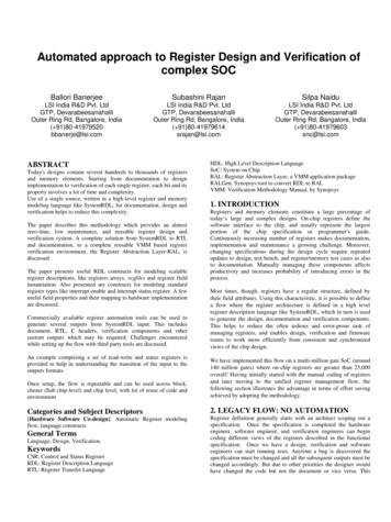
language is not required to describe stimulus. The stimulus block is alsocommonly called a test bench. Different test benches can be used to thoroughly testthe design block.Two styles of stimulus application are possible. In the first style, the stimulusblock instantiates the design block and directly drives the signals in the designblock. In Figure 2-6, the stimulus block becomes the top-level block. Itmanipulates signals clk and reset, and it checks and displays output signal 9.(Stimulus block)clkresetRipple CarryCounterFigure 2-6Stimulus Block Instantiates Design BlockThe second style of applying stimulus is to instantiate both the stimulus anddesign blocks in a top-level dummy module. The stimulus block interacts withthe design block only through the interface. This style of applying stimulus isshown in Figure 2-7. The stimulus module drives the signals d-clk and d-reset,which are connected to the signals clk and reset in the design block. It also checksand displays signal c-q, which is connected to the signal q in the design block.The function of top-level block is simply to instantiate the design and stimulusblocks.Hierarchical Modeling Concepts
Top-Level Blockd-clkStimulusBlock"resetFigure 2-71 j1reset Design BlocRipple CarrStimulus and Design Blocks instantiated in a Dummy Top-Level ModuleEither stimulus style can be used effectively.2.6 ExampleTo illustrate the concepts discussed in the previous sections, let us build thecomplete simulation of a ripple carry counter. We will define the design block andthe stimulus block. We will apply stimulus to the design block and monitor theoutputs. As we develop the Verilog models, you do not need to understand theexact syntax of each construct at this stage. At this point, you should simply try tounderstand the design process. We discuss the syntax in much greater detail inthe later chapters.2.6.1Design BlockWe use a top-down design methodology. First, we write the Verilog description ofthe top-level design block (Example 2-3), which is the ripple carry counter (seeSection 2.2, 4-bit Ripple Carry Counter).Example 2-3Ripple Carry Counter Top Blockmodule ripple-carry-counter(q,clk, reset) ;output [ 3 : 0 1 q;input clk, reset;20Verilog HDL: A Guide to Digital Design and Synthesis
Example 2-3T-FFT-FFT-FFT-FFRipple Carry Counter Top Block (Continued)tffO(q[O],clk, reset)tffl(q[l],q[O], resettff2 (q[2],q[l], resettff3 (q[3l,q[2], resetendmoduleIn the above module, four instances of the module T F F (T-flipflop) are used.Therefore, we must now define (Example 2-4) the internals of the module T-FF,which was shown in Figure 2-4.Example 2-4Flip-flop T-FFmodule T-FF (q, clk, reset);output q;input clk, reset;wire d;D-FF dff0 (q, d, clk, reset);not nl(d, q) ; / / not is a Verilog-provided primitive. case sensitiveendmoduleSince T-FF instantiates D-FF, we must now define (Example 2-5) the internals ofmodule D-FF. We assume asynchronous reset for the D-FF.FExample 2-5Flip-flop D-F/ / module D-FF with synchronous resetmodule D-FF(q, d, clk, reset);output q;input d, clk, reset;reg q;/ / Lots of new constructs.Ignore the functionality of the constructs./ / Concentrate on how the design block is built in a top-down fashion.always @(posedge reset or negedge clk)if (reset)q l'bO;Hierarchical Modeling Concepts21
Example 2-5Flip-flop D-F (Continued)/ / module D-FF with synchronous resetelseq d;endmoduleAll modules have been defined down to the lowest-level leaf cells in the designmethodology. The design block is now complete.Stimulus Block2.6.2We must now write the stimulus block to check if the ripple carry counter designis functioning correctly. In this case, we must control
digital circuit. From this point onward, the design process is done with the assistance of Computer-Aided Design (CAD) tools. Logic synthesis tools convert the RTL description to a gate-level netlist. A gate- level netl