Transcription
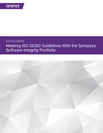
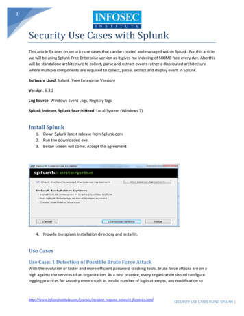
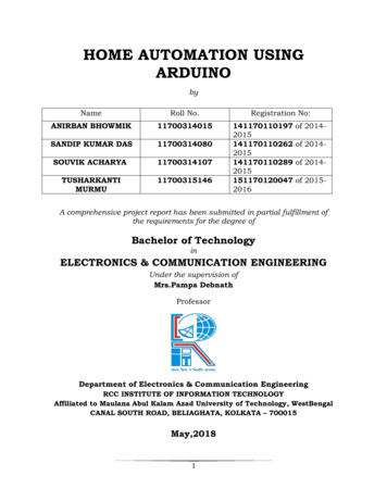
Simulating Verilog RTL using Synopsys VCSCS250 Tutorial 4 (Version 091209a)September 12, 2010Yunsup LeeIn this tutorial you will gain experience using Synopsys VCS to compile cycle-accurate executablesimulators from Verilog RTL. You will also learn how to use the Synopsys Waveform viewer totrace the various signals in your design. Figure 1 illustrates the basic VCS toolflow and RISC-Vtoolchain. For more information about the RISC-V toolchain consult Tutorial 3: Build, Run, andWrite RISC-V Programs.VCS takes a set of Verilog files as input and produces a simulator. When you execute the simulatoryou need some way to observe your design so that you can measure its performance and verify that itis working correctly. There are two primary ways to observe your design: (1) you can use displaystatements in your Verilog RTL to output textual trace information, or (2) you can instruct thesimulator to automatically write transition information about each signal in your design to a file.There is standard text format for this type of signal transition trace information called the ValueChange Dump format (VCD). Unfortunately, these textual trace files can become very large veryquickly, so Synopsys uses a proprietary compressed binary trace format called VCD Plus (VPD).You can view VPD files using the Synopsys waveform viewer called Discovery Visual RTL)ASMSourceCodeCSourceCodeVCSRISC-V toolchainRTLSimRISC-VBinaryExecute SIMVPDTestOutputsDVE GUIFigure 1: VCS Toolflow and RISC-V Assembler Toolchain
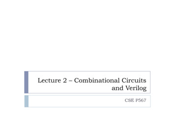
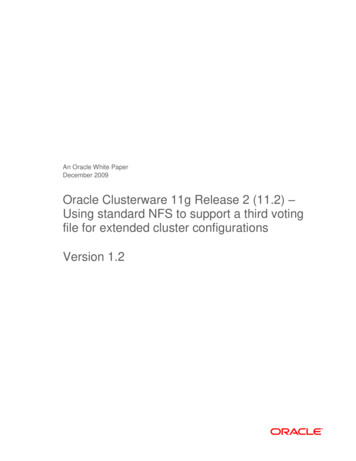
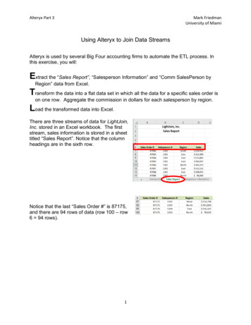
CS250 Tutorial 4 (Version 091209a), Fall 20102You will be using a simple unpipelined RISC-V v1 processor as your design example for this tutorial,and thus you will also learn how to build and run test codes on the processor simulator. Figure 2shows the block diagram for the example processor. Figure 1 shows the RISC-V toolchain whichstarts with an RISC-V assembly file and generates a binary file suitable to run on the cycle-accuratesimulator. This tutorial assumes you are familiar with the RISC-V ISA. For more information pleaseconsult the RISC-V Processor Specification.PCCmpeq?pc 4rd0rd1AddSignExtend 1ControlSignalsrdataaddrwdataData Memtohost enrwvalDecoderRegFileop1ir[11:0]rf wenRegFilevalir[19:15]wb selir[24:20]op0pc selInstructionMemir[24:20] 4branchtohosttestrig tohostFigure 2: Block diagram for Unpipelined RISC-V v1 ProcessorThe following documentation is located in the course locker cs250/manuals and provides additional information about VCS, DVE, and Verilog. vcs-user-guide.pdf - VCS User Guidevcs-quick-reference.pdf - VCS Quick Referencevcs dve-user-guide.pdf - Discovery Visual Environment User Guidevcs ucli-user-guide.pdf - Unified Command Line Interface User Guideieee-std-1364-1995-verilog.pdf - Language specification for the original Verilog-1995ieee-std-1364-2001-verilog.pdf - Language specification for Verilog-2001ieee-std-1364-2005-verilog.pdf - Language specification for .pdf - Standard for Verilog Register TransferLevel Synthesis ieee-std-1800-2005-sysverilog.pdf - Language specification for the original SystemVerilog2005 ieee-std-1800-2009-sysverilog.pdf - Language specification for SystemVerilog-2009
CS250 Tutorial 4 (Version 091209a), Fall 20103Getting startedYou can follow along through the tutorial yourself by typing in the commands marked with a ’%’symbol at the shell prompt. To cut and paste commands from this tutorial into your bash shell(and make sure bash ignores the ’%’ character) just use an alias to ”undefine” the ’%’ characterlike this:% alias % ""All of the CS250 tutorials should be ran on an EECS Instructional machine. Please see the coursewebsite for more information on the computing resources available for CS250 students. Once youhave logged into an EECS Instructional you will need to setup the CS250 toolflow with the followingcommands.% source cs250/tools/cs250.bashrcFor this tutorial you will be using an unpipelined RISC-V v1 processor as your example RTL design.Create a working directory and copy files from the course locker using the following commands.%%%%mkdir tut4cd tut4TUTROOT PWDcp -R cs250/examples/v-riscv-v1-1stage/* TUTROOTBefore starting, take a look at the subdirectories in the project directory. All of your projects willhave a similar structure. Source RTL should be placed in the src directory and test input filesshould be placed in the riscv-tests directory. The build directory will contain all generatedcontent including simulators, synthesized gate-level Verilog, and final layout. In this course youwill always try to keep generated content separate from your source RTL. This keeps your projectdirectories well organized, and helps prevent you from unintentionally modifying your source RTL.There are subdirectories in the build directory for each major step in the CS250 toolflow. Thesesubdirectories will contain scripts and configuration files necessary for running the tools requiredfor that step in the toolflow. For example, the build/vcs-sim-rtl directory contains a makefilewhich can build Verilog simulators and run tests on these simulators. For more information, pleaseconsult Tutorial 2: Bits and Pieces of CS250’s toolflow. You should browse the source code for theprocessor in src to become familiar with the design. The csrc directory contains Direct C sourcefiles. These C source files are used in the Verilog test harness to simulate memory, parse and loadELF files. Direct C is a very convenient way to glue Verilog simulation with C functions, whichwill be used through out the course. Please refer to the VCS user guide chapter 19 (C LanguageInterface) for more information on Direct C.Compiling the SimulatorIn this section you will first see how to run VCS from the command line, and then you will see howto automate the process using a makefile. To build the simulator you need to run the vcs compilerwith the appropriate command line arguments and a list of input Verilog files.
CS250 Tutorial 4 (Version 091209a), Fall 20104% cd TUTROOT/build/vcs-sim-rtl% vcs -full64 -PP lint all,noVCDE v2k -timescale 1ns/10ps \ vc list -CC "-I VCS HOME/include" \ define CLOCK PERIOD 1.25 \ define IMEM DELAY 0.4 \ define DMEM DELAY 0.4 \././src/defCommon.vh \././src/riscvInst.vh \././src/riscvConst.vh \././src/riscvProcCtrl.v \././src/riscvProcDpathRegfile.v \././src/riscvProcDpath.v \././src/riscvProc.v \././src/riscvTestHarness.v \././csrc/elf.cc \././csrc/memif.cc \././csrc/main.cc \By default, VCS generates a simulator named simv. The -full64 command line argument makesyou use the 64-bit version. -PP command line argument turns on support for using the VPD traceoutput format. The lint all,noVCDE argument turns on Verilog warnings except the VCDEwarning. Since it is relatively easy to write legal Verilog code which is probably functionallyincorrect, you will always want to use this argument. For example, VCS will warn you if youconnect nets with different bitwidths or forget to wire up a port. Always try to eliminate all VCScompilation errors and warnings. Since you will be making use of various Verilog-2001 languagefeatures, you need to set the v2k command line option so that VCS will correctly handle thesenew constructs. Verilog allows a designer to specify how the abstract delay units in their designmap into real time units using the ‘timescale compiler directive. To make it easy to change thisparameter you will specify it on the command line instead of in the Verilog source. vc list -CC"-I VCS HOME/include" arguments let you compile Direct C. After these arguments you list theVerilog source files and Direct C source files. After running this command, you should see textoutput indicating that VCS is parsing the Verilog files and compiling the modules. Notice thatVCS actually generates ANSI C code which is then compiled using gcc. When VCS is finished youshould see a simv executable in the build directory.Typing in all the Verilog source files on the command line can be very tedious, so you will usemakefiles to help automate the process of building your simulators. The following commands willfirst delete the simulator you previously built, and then regenerate it using the makefile.% cd TUTROOT/build/vcs-sim-rtl% rm -f simv% makeThe make program uses the Makefile located in the current working directory to generate the filegiven on the command line. Take a look at the Makefile located in build/vcs-sim-rtl. Makefilesare made up of variable assignments and a list of rules in the following form.
CS250 Tutorial 4 (Version 091209a), Fall 20105target : dependency1 dependency2 . dependencyNcommand1command2.commandNEach rule has three parts: a target, a list of dependencies, and a list of commands. When a desiredtarget file is “out of date” or does not exist, then the make program will run the list of commandsto generate the target file. To determine if a file is “out of date”, the make program comparesthe modification times of the target file to the modification times of the files in the dependencylist. If any dependency is newer than the target file, make will regenerate the target file. Locatein the makefile where the Verilog source files are defined. Find the rule which builds simv. Moreinformation about makefiles is online at http://www.gnu.org/software/make/manual.Not all make targets need to be actual files. For example, the clean target will remove all generated content from the current working directory. So the following commands will first delete thegenerated simulator and then rebuild it.% cd TUTROOT/build/vcs-sim-rtl% make clean% make simvBuilding RISC-V Test Assembly ProgramsA test program called riscv-v1 example.S is located locally in the riscv-tests directory. If youwant to add your own test programs, you would add them to this directory. There are additionalglobally installed RISC-V assembly test programs located in cs250/install/riscv-tests whichyou can use for your lab assignments and projects. The following command will build all of thelocal tests and run it on the RISC-V v2 ISA simulator.% cd TUTROOT/riscv-tests% make% make runPlease refer to Tutorial 3: Build, Run, and Write RISC-V Programs for more information aboutbuilding, running, and writing assembly test programs.Running the Simulator and Viewing Trace OutputNow that you have learned how to build the simulator and how to build RISC-V test assemblyprograms, you will learn how to execute RISC-V test assembly programs on the simulator. Thefollowing command runs the local riscv-v1 example.S test program on the simulator.% cd TUTROOT/build/vcs-sim-rtl% ./simv exe TUTROOT/riscv-tests/riscv-v1 exampleTry running a globally installed RISC-V test assembly program.
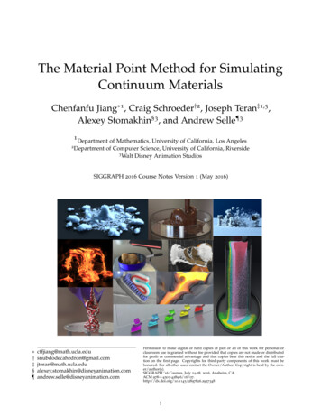
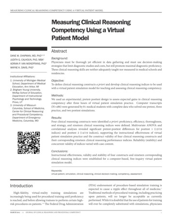
CS250 Tutorial 4 (Version 091209a), Fall 20106% cd TUTROOT/build/vcs-sim-rtl% ./simv exe UCB VLSI HOME/install/riscv-tests/riscv-v1 addiwYou should see some textual trace output showing the state of the processor on each cycle. Thetrace output includes the cycle number, reset signal, pc, instruction bits, register file accesses,testrig tohost signal, and the disassembled instruction. The test program does a series of loads andverifies that the loaded data is correct. After running all the tests, the program writes a one intothe tohost coprocessor register to indicate that all tests have passed. If any test fails, the programwill write a number greater than one into the tohost register. The test harness waits until thetestrig tohost signal is non-zero and displays either PASSED or FAILED as appropriate.In addition to the textual output, you should see a vcdplus.vpd in your build directory. Use thefollowing command to start the Synopsys Discovery Visual Environment (DVE) waveform viewerand open the generated VPD file.% dve -vpd vcdplus.vpd &Figure 3 shows the DVE Hierarchy window. You can use this window to browse the design’s modulehierarchy. Choose Window New Wave View to open a waveform viewer (see Figure 4). Toadd signals to the waveform window you can select them in the Hierarchy window and then rightclick to choose Add to Waves Recent.Figure 3: DVE Module Hierarchy WindowAdd the following signals to the waveform viewer.
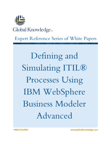
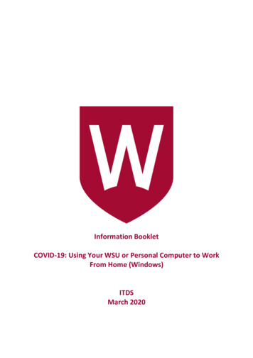
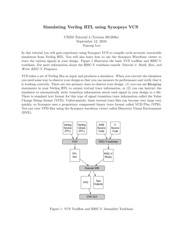
CS250 Tutorial 4 (Version 091209a), Fall 20107Figure 4: DVE Waveform Window rl sel pcriscvTestHarness.proc.dpath.pc rness.proc.dpath.ctrl iscvTestHarness.testrig tohostThe dasm module is a special tracing module which includes Verilog behavioral code to disassembleinstructions. The minidasm signal is a short text string which is useful for identifying whichinstruction is executing during each cycle. To display this signal as a string instead of a hexnumber, right click on the signal in the waveform viewer. Choose Set Radix ASCII from thepopup menu. You should now see the instruction type in the waveform window. Use Zoom ZoomOut to zoom out so you can see more of the trace at once. Figure 5 shows the waveforms in moredetail. You should be able to identify the addiw instructions correctly loading the register file withvarious constants and the addiw instructions writing the correct result into the register file. Thectrl sel pc control signal should remain low until the very end of the program when the codebranches to the pass code where it sets the tohost register to one.
CS250 Tutorial 4 (Version 091209a), Fall 20108Figure 5: Waveforms for unpipelined RISC-V v1 processor executing riscv-v1 addiwThe Verilog test harness provides two optional command line arguments in addition to the required exe argument as shown below:simv exe vmh-filename max-cycles integer verbose
12.09.2010 · File Sign Extend Decoder 1 Cmp Data Mem ir[24:20] branch pc 4 l rd0 rd1 Add Control Signals eq? l Reg File] n l rw PC tohost testrig_tohost tohost_en l op0 op1 addr wdata rdata ir[19:15] ir[11:0] Figure 2: Block diagram for Unpipelined RISC-V v1 Processor The following documentation is located in the course locker cs250/manuals and provides .