Transcription
Http://www.elego.cc37 SENSOR KIT TUTORIAL FOR UNO1 / 137
Http://www.elego.ccPrefaceOur CompanyEstablished in 2011, Elego Inc. is a professional manufacturer and exporter that is concernedwith the design, development production and marketing of arduino, 3d printers, raspberry piand STM32. We are located in Shenzhen which is known as Chinese Silicon Valley. All of ourproducts comply with international quality standards and are greatly appreciated in avariety of different markets throughout the world.Our official website is: Http://www.elego.ccOur USA amazon shop is: Http://www.amazon.com/shops/A2WWHQ25ENKVJ1Our TutorialThe tutorial is for beginners. In the tutorial, you can learn how to use arduino controller board,sensors and components. You can also learn the basic knowledge of all the parts. But if youwant to study arduino systematically, we recommend you to buy the book "ArduinoCookbook" which is written byMichael Margolis.Our after-salesIf you have any question or suggestion about our company, product or tutorial. Please sendus a email. Our email address is service@elego.cc.We will very appreciate and improve ourselves so that we can offer you a better service.2 / 137
Http://www.elego.ccPacking List3 / 137
Http://www.elego.cc4 / 137
Http://www.elego.ccLesson ListingLesson 0 Installing IDE . 6Lesson 1 Add Libraries. 14Lesson 2 TEMP AND HUMIDITYMODULE . 18Lesson 3 DS18B20 DIGITAL TEMPERATURE SENSOR MODULE . 23Lesson 4 BUTTON SWITCH MODULE . 28Lesson 5 FOUR TYPE OF SWITCH MODULE. 31Lesson 6 IR RECEIVER AND EMISSION . 37Lesson 7 Active and passive buzzer. 43Lesson 8 LASER MODULE . 49Lesson 9 SMD RGB MODULE AND RGB MODULE . 53Lesson 10 PHOTO-INTERRUPTER MODULE . 59Lesson 11 DUAL-COLOR COMMON-CATHODE LED . 63Lesson 12 PHOTORESISTOR MODULE . 68Lesson 13 BIG SOUND SENSOR MODULE AND SMALL SOUND SENSOR MODULE . 73Lesson 14 REED SWITCH AND MINI REED SWITCH MODULE . 78Lesson 15 DIGITAL TEMPERATURE MODULE . 85Lesson 16 LINEAR HALL AND ANALOG HALL MODULE . 91Lesson 17 FLAME SENSOR MODULE. 98Lesson 18 MENTAL TOUCH MODULE . 102Lesson 19 7 COLOR FLASH LED MODULE. 106Lesson 20 Magic light cup MODULE . 109Lesson 21 JOYSTICK MODULE . 112Lesson 22 TRACKING MODULE . 117Lesson 23 Infrared 38KHz obstacle avoidance module . 120Lesson 24 ROTARY ENCODERS MODULE . 125Lesson 25 1 CHANNEL RELAY MODULE . 130Lesson 26 HEARTBEAT MODULE . 1345 / 137
Http://www.elego.ccLesson 0 Installing IDEIntroductionIn this lesson, you will learn how to setup your computer to use Arduino and how to set aboutthe lessons that follow.Installing Arduino (Windows)The Arduino software that you will use to program your Arduino is available for Windows,Mac and Linux. The installation process is different for all three platforms and unfortunatelythere is a certain amount of manual work to install the software. There is no installer program,but rather you have to unzip a folder which gives you an Arduino folder that contains theArduino program and a few other items.In a separate step, you must then install USB drivers, which is the only bit that is a bit fiddly.Get started by visiting the Arduino.cc website. As of April 2014 we suggest v1.05 as 1.5 is stillin beta. If 1.5 is no longer in beta when you read this you can try it out!Start by downloading the zip file for Windows. There is only one version of the software,whether you are using Windows XP through to Windows 7.6 / 137
Http://www.elego.ccWhen the zip file has downloaded, extract the contents onto the Desktop, by right-clickingon the file and selecting 'Extract All.' from the pop-up menu.Next select your Desktop and click 'Extract'. You can move it somewhere else onto yourcomputer later, just by moving the folder, but for now, just keep it on the Desktop.The Arduino folder contains both the Arduino program itself and also the drivers that allowthe Arduino to be connected to your computer by a USB cable. Before we launch theArduino software, you are going to install the USB drivers.Plug one end of your USB cable into the Arduino and the other into a USB socket on yourcomputer. The power light on the LED will light up and you may get a 'Found New Hardware'message from Windows. Ignore this message and cancel any attempts that Windows makesto try and install drivers automatically for you.The most reliable method of installing the USB drivers is to use the Device Manager. This isaccessed in different ways depending on your version of Windows. In Windows 7, you firsthave to open the Control Panel, then select the option to view Icons, and you should findthe Device Manager in the list.Under the section ‘Other Devices’ you should see an icon for ‘unknown device’ with a littleyellow warning triangle next to it. This is your Arduino.7 / 137
Http://www.elego.ccRight-click on the device and select the top menu option (Update Driver Software.). Youwill then be prompted to either ‘Search Automatically for updated driver software’ or‘Browse my computer for driver software’. Select the option to browse and navigate to thearduino-1.0.2-windows\arduino1.0.2\drivers.8 / 137
Http://www.elego.ccClick 'Next' and you may get a security warning, if so, allow the software to be installed.Once the software has been installed, you will get a confirmation message.That's it, you are now ready for action, so Skip the next section on installation on Mac andLinux and move straight on to 'Boards and Ports'.Installing Arduino (Mac and Linux)Get started by visiting the Arduino.cc website and downloading the matching IDE for youroperating system. As of April 2014 we suggest v1.05 as 1.5 is still in beta. If 1.5 is no longer inbeta when you read this you can try it out!9 / 137
Http://www.elego.ccSave the install software to your desktop or whereverThe process for installing the Arduino software on the Mac is a lot easier than on the PC. Asbefore, the first step is to download the file. In the case of the Mac, it is a zip file.Once downloaded, double-click on the zip file, which will extract a single file called‘Arduino.app’. This is the whole Arduino application, just drag it into your ApplicationsFolder.10 / 137
Http://www.elego.ccYou can now find and launch the Arduino software in your Applications folder. As you aregoing to use it frequently, you may wish to right-click its icon in the dock and set it to Keep InDock.There are many different LINUX distributions and the instructions for each distribution are alittle different. The Arduino community has done a great job of putting together sets ofinstructions for each distribution. So follow the link below and select one of the ten or moredistributions on offer.Boards and PortsYou are now ready to start the Arduino Software, so whatever platform you are using, openthe Arduino folder and open the Arduino application contained within it.11 / 137
Http://www.elego.ccThis will start the Arduino IDE, but before you can get programming, you have to tell theArduino software which type of Arduino board you are using and also select the port it isconnecting to.To tell the Arduino IDE which type of board you are using. From the 'Tools' menu, selectBoard and then 'Arduino Uno' or 'Leonardo' as appropriate.Also on the 'Tools' menu, you will find the 'Serial Port' option. Select this option.12 / 137
Http://www.elego.ccIf you are using Windows, there will probably only be one option here and it will either sayCOM3 or COM4. Even though there is only one option, you will still need to select it.If you are using a Mac or Linux, there will be more options there, but it will usually be the topoption in the list, as this will be the device most recently plugged in. This is useful, as thename of the port may not look like it has anything to do with Arduino. It will probably becalled something like /dev/tty.usbmodemXXXX or /dev/ttyUSBn13 / 137
Http://www.elego.ccLesson 1 Add LibrariesOnce you are comfortable with the Arduino software and using the built-in functions,you may want to extend the ability of your Arduino with additional libraries.What are Libraries?Libraries are a collection of code that makes it easy for you to connect to a sensor, display,module, etc. For example, the built-in LiquidCrystal library makes it easy to talk to characterLCD displays. There are hundreds of additional libraries available on the Internet fordownload. The built-in libraries and some of these additional libraries are listed in thereference. To use the additional libraries, you will need to install them.How to Install a LibraryUsing the Library ManagerTo install a new library into your Arduino IDE you can use the Library Manager (availablefrom IDE version 1.6.2). Open the IDE and click to the "Sketch" menu and then IncludeLibrary Manage Libraries.14 / 137
Http://www.elego.ccThen the library manager will open and you will find a list of libraries that are already installedor ready for installation. In this example we will install the Bridge library. Scroll the list to find it,then select the version of the library you want to install. Sometimes only one version of thelibrary is available. If the version selection menu does not appear, don't worry: it is normal.Finally click on install and wait for the IDE to install the new library. Downloading may taketime depending on your connection speed. Once it has finished, an Installed tag shouldappear next to the Bridge library. You can close the library manager.You can now find the new library available in the Include Library menu. If you want to addyour own library open a new issue on github.15 / 137
Http://www.elego.ccImporting a .zip LibraryLibraries are often distributed as a ZIP file or folder. The name of the folder is the name of thelibrary. Inside the folder will be a .cpp file, a .h file and often a keywords.txt file, examplesfolder, and other files required by the library. Starting with version 1.0.5, you can install 3rdparty libraries in the IDE. Do not unzip the downloaded library, leave it as is.In the Arduino IDE, navigate to Sketch Include Library. At the top of the drop down list,select the option to "Add .ZIP Library''.You will be prompted to select the library you would like to add. Navigate to the .zip file'slocation and open it.Return to the Sketch Import Library menu. You should now see the library at the bottom ofthe drop-down menu. It is ready to be used in your sketch. The zip file will have beenexpanded in the libraries folder in your Arduino sketches directory.NB: the Library will be available to use in sketches, but examples for the library will not beexposed in the File Examplesuntil after the IDE has restarted.Manual installationTo install the library, first quit the Arduino application. Then uncompress the ZIP file containingthe library. For example, if you're installing a library called "ArduinoParty", alledArduinoParty,withfileslikeArduinoParty.cpp and ArduinoParty.h inside. (If the .cpp and .h files aren't in a folder, you'llneed to create one. In this case, you'd make a folder called "ArduinoParty" and move into itall the files that were in the ZIP file, like ArduinoParty.cpp and ArduinoParty.h.)16 / 137
Http://www.elego.ccDrag the ArduinoParty folder into this folder (your libraries folder). Under Windows, it will likelybe called "My Documents\Arduino\libraries". For Mac users, it will likely be called"Documents/Arduino/libraries". On Linux, it will be the "libraries" folder in your sketchbook.Your Arduino library folder should now look like this (on Windows):My rty.cppMy rty.hMy or like this (on Mac and uinoParty/examples.There may be more files than just the .cpp and .h files, just make sure they're all there. (Thelibrary won't work if you put the .cpp and .h files directly into the libraries folder or if they'renested in an extra folder. For example: Documents\Arduino\libraries\ArduinoParty.cpp oParty\ArduinoParty.cpp won't work.)Restart the Arduino application. Make sure the new library appears in the Sketch- ImportLibrary menu item of the software. That's it! You've installed a library!SummaryIn this lesson, we will install all the libraries which we will use in the tutorial. So in the followinglesson, we don't need to install them anymore. We just connect the component as theschematic and upload the code provided. Then the kit will work.17 / 137
Http://www.elego.ccLesson 2 TEMP AND HUMIDITYMODULEOverviewIn this tutorial we will learn how to use a DHT11 Temperature and Humidity Sensor.It’s accurate enough for most projects that need to keep track of humidity andtemperature readings.Again we will be using a Library specifically designed for these sensors that will make ourcode short and easy to write.Component Required:(1) x Elego Uno R3(1) x USB cable(1) x DHT11 module(x) x F-M wiresComponent IntroductionTemp and humidity sensor:18 / 137
Http://www.elego.ccDHT11 digital temperature and humidity sensor is a composite Sensor contains a calibrateddigital signal output of the temperature and humidity. Application of a dedicated digitalmodules collection technology and the temperature and humidity sensing technology, toensure that the product has high reliability and excellent long-term stability. The sensorincludes a resistive sense of wet components and an NTC temperature measurementdevices, and connected with a high-performance 8-bit microcontroller.Applications: HVAC, dehumidifier, testing and inspection equipment, consumer goods,automotive, automatic control, data loggers, weather stations, home appliances, humidityregulator, medical and other humidity measurement and control.Product parametersRelative humidity:Resolution: 16BitRepeatability: 1% RHAccuracy: At 25 5% RHInterchangeability: fully interchangeableResponse time: 1 / e (63%) of 25 6s1m / s air 6sHysteresis: 0.3% RHLong-term stability: 0.5% RH / yr inTemperature:Resolution: 16Bit19 / 137
Http://www.elego.ccRepeatability: 0.2 Range: At 25 2 Response time: 1 / e (63%) 10SElectrical CharacteristicsPower supply: DC 3.5 5.5VSupply Current: measurement 0.3mA standby 60μASampling period: more than 2 secondsPin Description:1, the VDD power supply 3.5 5.5V DC2 DATA serial data, a single bus3, NC, empty pin4, GND ground, the negative powerTypical ApplicationConnectionSchematic20 / 137
Http://www.elego.ccwiring diagramResult21 / 137
Http://www.elego.ccUpload the program then open the monitor, we can see the data as below:(It shows thetemperature of the environment, we can see it is 21 degree)22 / 137
Http://www.elego.ccLesson 3 DS18B20 DIGITAL TEMPERATURESENSOR MODULEOverviewIn this experiment, we will learn how to use DS18B20 module test the environmentaltemperature and make a thermometer.Since the previous temperature sensor output is analog. So we need to add additional A/Dand D/A chip into the line transformation. More -over, the Arduino external port is not richresources and the utilization rate is not high. These cause a big challenge. So we are createthe Ds18b20 module.The new DS18B20 Temperature Sensor Module is very good solve the problem. It have canfullyapplytheArduinoplatform.can easily forma sensor network through using this module.Component Required:(1) x Elego Uno R3(1) x USB cable(1) x DS18B20 module(x) x F-M wires23 / 137Users
Http://www.elego.ccComponent IntroductionDS18B20:24 / 137
Http://www.elego.ccPrincipleDS18B20 module is using a single bus. The power supply voltage range of 3.0 V to 5.5 V andno standby power supply. It can Measuretemperaturerangefor-55degreeto 125degreewith accuracy of /-0.5 C.The programmable DPI of temperature sensor is From 9 to 12. temperature conversion is 12digits lattice type. maximum is 750 milliseconds. Families can be defined non-volatiletemperature alarm Settings.Each DS18B20 contains a unique serial number so that multiple ds18b20 scan exist in a bus.ConnectionSchematic25 / 137
Http://www.elego.ccwiring diagramResult26 / 137
Http://www.elego.ccTemperature sensor can detect temperature in numbers of different places at the sametime.Upload the program then open the monitor, we can see the data as below:27 / 137
Http://www.elego.ccLesson 4 BUTTON SWITCH MODULEOverviewIn this experiment, we will learn how to use button switch.Component Required:(1) x Elego Uno R3(1) x USB cable(1) x Button module(x) x F-M wiresComponent IntroductionPUSH SWITCHES:Switches are really simple components. When you press a button or flip a lever, theyconnect two contacts together so that electricity can flow through them.The little tactile switches that are used in this lesson have four connections, which can be alittle confusing.28 / 137
Http://www.elego.ccActually, there are only really two electrical connections, as inside the switch package pinsB and C are connected together, as are A and D.PrincipleBUTTON SWITCH and number 13 port have the built-in LED simple circuit. To produce aswitch flasher, we can use connect the digital port 13 to the built-in LED and connect theBUTTON SWITCHS port to number3 port of Elego Uno board. When the switch sensing, LEDtwinkle light to the switch signal.ConnectionSchematic29 / 137
Http://www.elego.ccwiring diagramResultConnect the circuit as above and upload the program. Then push the button, you can seeled on and off.30 / 137
Http://www.elego.ccLesson 5 FOUR TYPE OF SWITCH MODULEOverviewIn this experiment, we will learn how to use switch modules.Including shock switch module, mercury switch module, tilt switch module and knock switchmodule.31 / 137
Http://www.elego.ccComponent Required:(1) x Elego Uno R3(1) x USB cable(1) x Shock switch module(1) x Mercury switch module(1) x tilt switch module(1) x Knock switch module(x) x F-M wiresPrincipleswitch and number 13 port have the built-in LED simple circuit. To produce a SWITCH flasher,we can use connect the digital port 13 to the built-in LED and connect the SWITCH S port tonumber 3 port of Elego Uno board. When the SWITCH sensing, LED twinkle light to the SWITCHsignal.ConnectionSchematic32 / 137
Http://www.elego.ccwiring diagram33 / 137
Http://www.elego.cc34 / 137
Http://www.elego.ccResult35 / 137
Http://www.elego.ccConnect the circuit as above and upload the program. Then lean or shock the sensor, youcan see led on and off.36 / 137
Http://www.elego.ccLesson 6 IR RECEIVER AND EMISSIONOverviewIn this experiment, we will learn how to use Infrared Receiver and IR Emission module.In fact now in our daily life they play an important role, a lot of household electricalappliances are used to this kind of device, such as air conditioning, TV, DVD, etc. Actually itis based on its wireless remote sensing and it is very convenient by using them.Component Required:(1) x Elego Uno R3(1) x USB cable(1) x IR Receiver module(1) x IR Emission module37 / 137
Http://www.elego.cc(x) x F-M wiresComponent IntroductionIR RECEIVER SENSOR:IR detectors are little microchips with a photocell that are tuned to listen to infrared light.They are almost always used for remote control detection - every TV and DVD player hasone of these in the front to listen for the IR signal from the clicker. Inside the remote control isa matching IR LED, which emits IR pulses to tell the TV to turn on, off or change channels. IRlight is not visible to the human eye, which means it takes a little more work to test a setup.There are a few difference between these and say a CdS Photocells:IR detectors are specially filtered for Infrared light, they are not good at detecting visiblelight. On the other hand, photocells are good at detecting yellow/green visible light, notgood at IR light IR detectors have a demodulator inside that looks for modulated IR at 38 KHz. Justshining an IR LED won't be detected, it has to be PWM blinking at 38KHz. Photocells donot have any sort of demodulator and can detect any frequency (including DC) withinthe response speed of the photocell (which is about 1KHz) IR detectors are digital out - either they detect 38KHz IR signal and output low (0V) orthey do not detect any and output high (5V). Photocells act like resistors, the resistancechanges depending on how much light they are exposed to.What You Can Measure38 / 137
Http://www.elego.ccAs you can see from these datasheet graphs, the peak frequency detection is at 38 KHz andthe peak LED color is 940 nm. You can use from about 35 KHz to 41 KHz but the sensitivity willdrop off so that it wont detect as well from afar. Likewise, you can use 850 to 1100 nm LEDsbut they wont work as well as 900 to 1000nm so make sure to get matching LEDs! Check thedatasheet for your IR LED to verify the wavelength.Try to get a 940nm - remember that 940nm is not visible light (its Infra Red)!PrincipleFirstly, let's know the structure of the infrared receiving head: there are two importantelements inside the infrared receiving head, IC and PD. IC is receiving head processingcomponents, mainly composed of silicon and circuit. It is a highly integrated device. Themain function is filter, plastic, decoding, amplification, etc. PD is a photosensitive diode. Themain function is to receive the light signal.Below is a brief working principle diagram:39 / 137
Http://www.elego.ccInfrared emitting diode launch out the modulation signal and infrared receiver head willreceive, decode, filter and soon to regain the signal.Infrared emitting diode: keep clean and in good condition. All the parameters in theprocessofworkingshallnotexceedthelimit value(positiveTo thecurrent30 60mA, positive pulse current 0.3 1A, reverse voltage 5V, dissipation power 90mW,working temperature range -25 80 , and storage temperature range between 40 100 ,the welding temperature 260 ) infrared to be with a closed head should be matching use,otherwise it will influence the sensitivity.ConnectionSchematic40 / 137
Http://www.elego.ccwiring diagram41 / 137
Http://www.elego.ccResult42 / 137
Http://www.elego.ccLesson 7 Active and passive buzzerOverviewIn this experiment, we will learn how to use buzzer module.With the Arduino we can complete a lot of interactive work, commonly what we used is thelight shows. And we has been use the LED small lights in the experiment before. In thisexperiment we will make the circuit having noise. The common components that canmake sound are buzzer and speakers.Compared to the speaker, buzzer is more simpleand easy to use so in this experiment we adopts the buzzer.Component Required:(1) x Elego Uno R343 / 137
Http://www.elego.cc(1) x USB cable(1) x Active buzzer module(1) x Passive buzzer module(x) x F-M wiresComponent IntroductionActive Buzzer:As a type of electronic buzzer with integrated structure, buzzers, which are supplied by DCpower, are widely used in computers, printers, photocopiers, alarms, electronic toys,automotive electronic devices, telephones, timers and other electronic products for voicedevices. Buzzers can be categorized as active and passive ones (see the following picture).Turn the pins of two buzzers face up, and the one with a green circuit board is a passivebuzzer, while the other enclosed with a black tape is an active one.The difference between an active buzzer and a passive buzzer is:An active buzzer has a built-in oscillating source, so it will make sounds when electrified. Buta passive buzzer does not have such source, so it will not tweet if DC signals are used;instead, you need to use square waves whose frequency is between 2K and 5K to drive it.The active buzzer is often more expensive than the passive one because of multiple built-inoscillating circuits.Passive Buzzer:Passive buzzer, in fact, just use PWM generating audio, drives the buzzer, allowing the air tovibrate, can sound. Appropriately changed as long as the vibration frequency, it cangenerate different sound scale. For example, sending a pulse wave can be generated523Hz Alto Do, pulse 587Hz can produce midrange Re, 659Hz can produce midrange Mi. Ifyou then with a different beat, you can play a song. Here be careful not to use the Arduinoanalog Write () function to generate a pulse wave, because the frequency analog Write ()is fixed (500Hz), no way to scale the output of different sounds.Distinguish between Active and Passive BuzzerTeach you to distinguish between active and passive buzzerNow a small buzzer on the market because of its small size (diameter of only ll mm), lightweight, low price, solid structure, and is widely used in a variety of needs audible electrical44 / 137
Http://www.elego.ccequipment, electronic production and microcontroller circuits, etc. .From the exterior, two kinds of buzzer seems the same, but a closer look, a slight differencebetween the height of the active buzzer a, height of 9mm, and passive buzzer b height of8mm. When the buzzer as the two pins are facing up, you can see there is a green circuitboard is passive buzzer, no closed circuit boards with a vinyl is active buzzer .Further determine the active and passive buzzer, you can also use a multimeter to test theresistance profile Rxl file: buzzer with black pen then " " pin, the red pen to touch on anotherpin back and forth, if trigger a cracking, cracking sound and the resistance only 8Ω (or 16Ω)is passive buzzer; If you can emit continuous sound, and the resistance in Europe and morethan a few hundred, and is an active buzzer.Active buzzer directly connected to the rated power (new buzzer has stated on the label)can be a continuous sound; rather passive electromagnetic buzzer and speaker are thesame, you need to take in order to sound the audio output circuit .ConnectionSchematic45 / 137
Http://www.elego.ccwiring diagram46 / 137
Http://www.elego.ccResultAfter we connect the circuit as the picture, we upload the program of each module. Wecan hear that the active buzzer can make sound in one voice. And the passive can sing asong.47 / 137
Http://www.elego.cc48 / 137
Http://www.elego.ccLesson 8 LASER MODULEOverviewI n this experiment, we will learn how to use laser module.Component Required:(1) x Elego Uno R3(1) x USB cable(1) x Laser module(x) x F-M wiresComponent IntroductionLaser sensor:49 / 137
Http://www.elego.ccConnectionSchematic50 / 137
Http://www.elego.ccwiring diagram51 / 137
Http://www.elego.ccResultAfter we connect the circuit as the picture, we upload the program. We can see themodule can emission lasers.52 / 137
Http://www.elego.ccLesson 9 SMD RGB MODULE AND RGB MODULEOverviewIn this experiment, we will learn how to use SMD RGB module and RGB module.Actually, the function of SMD RGB module and RGB module are almost the same. But wecan choose the shape we like or we need.SMD RGB LED module and RGB module are made from a patch of full-color LED. B
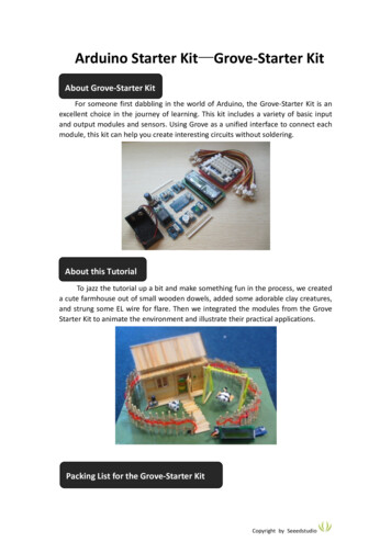
The tutorial is for beginners. In the tutorial, you can learn how to use arduino controller board, sensors and components. You can also learn the basic knowledge of all the parts. But if you want to study arduino systematically, we recommend you to buy the book "Arduino Cookbo
