Transcription
TECHNICAL SERVICESELITE SERIES SURGICAL TABLESOPERATORS MANUALMODEL 6000/6001INCLUDING BATTERY MODELS17
MODEL ELITE 6001KSKYTRON STANDARD LIMITED WARRANTYSKYTRON, a Division of the KMW Group, Inc. (SKYTRON) warrants all new products sold by it directly or through a dealer or otherauthorized representative, with exception to replacement parts, spares, bulbs (surgical lights), pads, and accessory items (surgical tables)to be free from defects in material or workmanship, under normal use and service, for a period of two (2) years. This warranty shall includethe cost of repair or replacement of defective parts including the cost of service labor and travel time to the site of equipment use. Delayscaused by the user in accessing the equipment for repair will be chargeable at the normal hourly rate for service by SKYTRON’s authorizedservice representative. The warranty period shall begin with the initial operation or one (1) year after receipt of the product, whichever shalloccur first.Replacement parts, spares, bulbs (surgical lights), pads and accessory items (surgical tables) are warranted to be free from defects in materialor workmanship, under normal use and service, for a period of ninety (90) days from receipt by the ultimate user, with exception to replacementparts supplied by SKYTRON, for products under warranty, which shall be covered for any remaining period of the original product warranty,or for 90 days, whichever is of greater benefit to the ultimate user.SKYTRON’s responsibility and liability shall be limited to the repair or replacement of any part which we, SKYTRON, determine to be defectivewithin the applicable warranty period. Minor adjustments required as a result of normal wear during the use of the product within the warrantyperiod are not covered under warranty. The labor portion of this warranty is covered by SKYTRON’s Authorized Service Agent. Repairsmade by others are not authorized nor covered by SKYTRON with respect to labor costs.SKYTRON shall not be liable for any other expense, loss or damage, whether direct, incidental, consequential or exemplary arising in connectionwith the sale or use of or the inability to use SKYTRON products.NO EXPRESS WARRANTY IS GIVEN BY SKYTRON WITH RESPECT TO ITS PRODUCTS EXCEPT AS SPECIFICALLY SET FORTHHEREIN. ANY WARRANTY IMPLIED BY LAW, INCLUDING ANY WARRANTY OF MERCHANTABILITY OR FITNESS FOR A PARTICULARPURPOSE, IS EXPRESSLY LIMITED TO THE TWO-YEAR AND 90-DAY TERMS SET FORTH ABOVE. THE FOREGOING STATEMENTSOF WARRANTY ARE EXCLUSIVE AND IN LIEU OF ALL OTHER REMEDIES.No dealer, agent, employee or other representative of SKYTRON is authorized to extend or enlarge this warranty.REV. 3/97Although current at the time of publication, SKYTRON’s policy of continuous development makes thismanual subject to change without notice.13
TABLE OF CONTENTSTitlePageSPECIAL USER ATTENTION . 1SECTION I INTRODUCTION .1-1. General.1-2. Power Requirements .1-3. Pendant Control Unit .1-4. Floor Lock/Brake System .22233SECTION II BATTERY TABLE OPERATION . 42-1. AC 120V Operation . 42-2. Battery Operation . 42-3. Automatic Shut-Off . 52-4. Charging the Battery . 52-5. Emergency Back-Up Controls . 5SECTION III OPERATION . 63-1. Electrical Power . 63-2. Positioning Functions . 6a. Floor Lock/Brake system . 6b. Emergency Brake Release . 6c. Trendelenburg . 7d. Lateral Tilt . 7e. Back Section . 7f. Elevation . 8g. Leg Section . 8h. Flex Positioning . 8i. Return To Level . 8j. Pendant Control Storage . 93-3. Head Section . 93-4. 180 Degree Table Top Rotation. . 93-5. Leg Section (Elite 6000 only) . 103-6. Kidney Lift . 103-7. Specialty Positioning . 11SECTION IV MAINTENANCE. 114-1. Preventive Maintenance . 114-2. Service . 1115
SPECIAL USER ATTENTIONThe extreme positioning capabilities of the 6000Series Table requires special attention for possibleinterference points when using multiple functionpositioning. As with the operation of any surgicaltable, a certain amount of care should be exercisedto position the patient safely. Although the thickpads and sheets substantially protect the patient,pinch points, located at the joints of the top sectionshould always be considered. BE SURE THATTHE ARMS, HANDS AND FINGERS OF THEPATIENT AND THOSE OF THE OPERATINGROOM PERSONNEL ARE CLEAR OF ALL MOVING PARTS BEFORE MOVING THE TABLE.Proper restraints should always be used for patientsafety.IMPORTANTThe leg section may hit the table base or the floorif both the leg and elevation systems are placed intheir full down position.Certain accessories such as the Uro-Drain Tray,Armboards and X-Ray top can be damaged whenchanging the position of the table top sections.Always look first to see if a desired movement isgoing to interfere with any accessories in use.WARNINGAlways lock the table top in position after rotation.DO NOT rotate the top with an unevenly distributedpatient weight load as instability may result.The operator has the ultimate responsibility ofpreventing damage to the table and surroundingequipment or possible injury to the patient or staff.In general, common sense will dictate when thereis a potential hazard.WARNING Make sure the TOP ROTATION LOCK HANDLEis tightened and the brakes are set before transferring the patient.The following precautions should be reviewedby all personnel prior to operating the table. Exercise caution with the table top rotated 90 tothe base since an improperly distributed patientweight load may cause the table to be tipped over.WARNINGDO NOT use the table in the presence of FLAMMABLE GASES (Flammable gases are not commonly used in the U.S.).NOTEIn case of a power failure or an electrical problemwithin the table, the emergency brake releasesystem can be used to move the table. The controllever for this function is located on the side of thetable base and is identified by an EMERGENCYBRAKE RELEASE label. Turn the lever counterclockwise to release the brakes.IMPORTANT The Emergency Brake Release Valve must beclosed and tightened (clockwise) before any hydraulic function will operate. If the Emergency Brake Release Valve has beenoperated, the UNLOCK button on the pendantcontrol will have to be pressed before brakes willlock again.WARNINGDO NOT unlock brakes when a patient is on thetable. An uneven patient weight load may causeinstability.NOTEIf brakes fail to set, make sure the EmergencyBrake Release Lever is tight (clockwise).NOTENormal table top position is with the head (andback) section over the power cord end of the base.NOTEWith an evenly distributed patient weight load, alltable positioning functions will operate smoothlyand quietly with a patient weight of up to 500pounds.CAUTIONTo prevent damage to the kidney lift, make sure thekidney lift is completely down before raising theback section.CAUTIONDO NOT sit on the end of the leg sections (6000Series) as damage may result.1
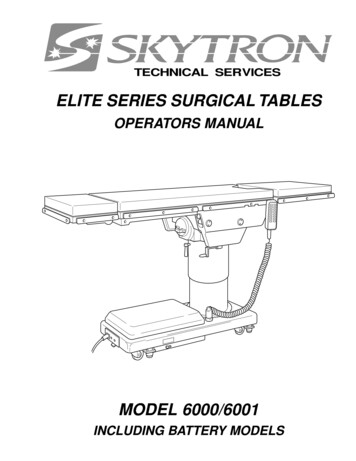
SECTION I INTRODUCTIONHEADSECTIONBACKSECTIONOPT. KIDNEYLIFTLEGSECTIONSEATSECTIONSPLIT LEGSECTIONSPENDANTCONTROLHEAD SECTIONRELEASE BAR(NOT SHOWN)SIDERAILTOP ROTATIONHANDLEMODEL 6000(K)SERVICE ACCESSCOVERMAIN POWERSWITCHMODEL 6001(K)Figure 1-1. Elite 6000/6001(K)1-1. General1-2. Power RequirementsSKYTRON’s Elite 6000 and 6001 Series SurgicalTables are electro-hydraulically operated, generalpurpose surgical tables. See figure 1-1.The Elite 6000/6001 series Surgical Tables require a 120VAC, 60 Hz electrical power supply.The table is equipped with a 15 foot long powercord with a standard three prong, hospital gradeplug. The electrical protection fuses are locatedbehind a cover plate in the electrical enclosure onthe front edge of the base. See figure 1-2. Themain power ON/OFF switch is located on theelectrical enclosure.The two models are identical except for the legsections. The 6000 series has manually positioned, independent, split-leg sections. The 6001series has a single, electro-hydraulically operatedleg section.A"K" after the model number designates a built-inkidney bridge.An "R" after the model number designates thereturn to level feature.The electro-hydraulic positioning functions operated by the hand-held, push button, pendant control unit are: trendelenburg, lateral tilt, back section,elevation, leg section (6001 only), flex/reflex, returnto level, and the floor lock/brake system.Manual controls are provided for head sectionpositioning, table top rotation, emergency brakerelease, leg section (6000) and kidney lift.2ELECTRICALENCLOSUREPOWERCORDMAIN POWERSWITCHCOVERPLATEFUSEFigure 1-2. Power Switch and Fuse Location
1-3. Pendant Control Unit1-4. Floor Lock/Brake SystemThe hand-held pendant control unit (figure 1-3) hasa non-slip rubber cover which assures a positivegrip during use. A spring clip hanger located on theback of the control allows it to be stored on thetrendelenburg cylinder cap bracket or the tableside rails.The floor lock/brake system consists of four selfleveling, hydraulic brake cylinders which raise andsupport the table base off from the casters. Pressthe TABLE UP button on the pendant control to setthe table’s brakes. An electronic timer will activatethe brake system until the brakes are completelyset, approximately 8-10 seconds.CLIPNDTRE.REV DNTRETILTTHRIGTILTTLEFKBAC NWDOKBACUPLETABPU*LEGNWDOLEGUPLEXREFEAKBR BWNDOLOCNOTEActivating any function button will activate the brake system. Using theTABLE UP function to set the brakesprovides a visual assurance that thebrakes are locked. As the brake cylinders are extending, the entire table willmove slightly. When the table top begins to elevate, the brakes are fullylocked.ERPOWONPOWERINDICATORFigure 1-3. Pendant Control UnitThe function push buttons are identified with abbreviated descriptions for all functions. See figure1-4. The trendelenburg and table up buttons arered, the remaining buttons are all black.To unlock the brakes, press the BRAKE UNLOCKbutton and release. The brakes will retract automatically in approximately 7-8 seconds.WARNINGDO NOT unlock brakes when a patientis on the table. An uneven patientweight load may cause instability.NOTEIn case of a power failure or an electrical problem within the table, the emergency brake release system can beused to move the table. The controllever for this function is located on theside of the table base and is identifiedby an EMERGENCY BRAKE RELEASElabel. Turn the lever counterclockwiseto release the brakes.IMPORTANT The Emergency Brake Release Valvemust be closed and tightened (clockwise) before any hydraulic function willoperate. If the Emergency Brake Release Valvehas been operated, the BRAKE UNLOCK button on the pendant controlwill have to be pressed before brakeswill lock again.Figure 1-4. Function Push Buttons3
SECTION II BATTERY TABLE OPERATION2-1. AC 120V Operationa. Be sure the power cord is plugged into aproperly grounded, Hospital Grade, 120VAC outlet. Make sure the power cord is routed to the outletto prevent it from being in the way of operatingpersonnel.b. Depress the main power ON/OFF switchlocated on the electrical enclosure. See figure 2-1.The green AC 120V, Power-On indicator lightlocated in the lower right corner of the pendantcontrol will illuminate. See figure 2-2.BATTERY CHARGINGINDICATOR LIGHTNOTE If brakes fail to set, make sure theEmergency Brake Release Lever istight (clockwise). If the Emergency Brake Release Valvehas been operated, the BRAKE UNLOCK button on the pendant controlwill have to be pressed before brakeswill lock again.NOTE Turning the Main Power Switch ONwill change the table operation to 120VAC power regardless of the position ofthe BATT button. If Battery operation is activated whileMain Power Switch is ON there will beapproximately a 4 second delay beforeBattery operation activates.2-2. Battery OperationELECTRICAL ENCLOSUREMAIN POWER SWITCHFigure 2-1. Main Power SwitchTRENDELENBURGREVERSETRENDELENBURGLATERALTILT LEFTBACK UPTABLE UPLEG UPFLEXRETURN(KR ONLY)BATTERY ON/OFFSELECTOR BUTTONBATTERY POWERINDICATOR RNBRAKEUNLOCKLATERALTILT RIGHTBACK DOWNTABLE DOWNLEG DOWNNOTEThe table will operate correctly on battery power with the power cord connected to a wall outlet or disconnected.REFLEXBRAKERELEASEBATT* PRESS TO LOCK BRAKESBATTERYPOWER ONAC120V POWER ONINDICATOR LIGHT(GREEN)Figure 2-2. Pendant Controlc. The table is now ready for 120VAC operation.Press the TABLE UP button on the pendant controlto set the table’s brakes. An electronic timer willactivate the brake system until the brakes arecompletely set, approximately 8-10 seconds. Pressthe desired function button to position the table.4a. Make sure the green, AC 120V, Power-Onindicator light, on the hand-held pendant control, isOFF. See figure 2-2. If the indicator light is ON,depress the main power ON/OFF switch, locatedon the electrical enclosure to turn AC120V operation OFF.b. Press the BATT button on the hand-heldpendant control. The amber BATTERY indicatorlight, located in the lower left corner of the pendantcontrol, will illuminate. This confirms that the tableis now being operated with battery power.c. The table is now ready to operate on batterypower. Press TABLE UP button on the pendantcontrol to set the table’s brakes. An electronictimer will activate the brake system until the brakesare completely set, approximately 8-10 seconds.Press desired function button to position the table.d. To extend the battery charge life, turn theBATTERY power OFF with the pendant controlwhen the table is not going to be used.
NOTEBattery Operation must be turned OFFat the pendant control. It can not beturned Off using the main power switch.2-5. Emergency Back-up Controlsa. The emergency back-up control switches arelocated under the access door on the serviceaccess cover in the table base. See figure 2-3.2-3. Automatic Shut-Offa. To prevent unnecessary discharge of thebattery, a timer is built into the battery circuit. Thistimer will automatically shut the battery power OFFafter 3-4 hours of table inactivity.b. To turn the table “ON” again, simply press theBATT button on the pendant control and the amberindicator light will illuminate. Select any controlbutton to operate the table.2-4. Charging the Batterya. If the battery needs to be charged whenoperating the table on battery power, the amberindicator light on the pendant control will begin toblink. At this time the battery needs to be recharged.NOTEWhen the amber light starts to blink(indicating low power in battery) thetable will operate for approximately 5continuous minutes, typically longenough to use the table for the rest ofthe day.FUNCTION CONTROLACCESS DOORFigure 2-3. Emergency Controls Locationb. In the event of either a power failure or aproblem with the hand-held pendant control, thetable can be operated using the emergency backup switches. Simply push the desired emergencyswitch in the appropriate direction to operate thetable functions. See figure 2-4. These switches arespring-loaded so they return to the neutral orcenter position when released.LAT. TILTLEFT/RIGHTTABLEUP/DOWNb. To recharge the battery simply plug thepower cord into a 120VAC wall outlet, if notalready plugged in. Turn the main power ON/OFF switch ON by depressing it. The green batterycharging light, located next to the power cord, willilluminate.c. A full battery charge will last approximately 2weeks under normal operating conditions. However, it is recommended to charge the batteries atthe end of each week to establish a normal routineprotocol.NOTEThe table can be operated on 120VACpower while the battery is being recharged. The green AC 120V indicatorlight (on the pendant control) will illuminate confirming 120VAC operation.TRENDREV. TRENDBACKUP/DOWNLEGUP/DOWNFigure 2-4. Emergency Back-Up ControlsNOTEThe emergency back-up controlswitches will function when the table isoperating on 120VAC power, batterypower, or turned off.5
SECTION III OPERATION3-1. Electrical Powera. Floor Lock/Brake System. To activate thea. Check to be sure the power cord is pluggedbrakes without affecting table positioning, pressinto a properly grounded, Hospital Grade, 120VACthe TABLE UP button. See figure 3-3. Theoutlet. Make sure the power cord is routed so as toelevation cylinder will not function until the brakesprevent it from being in the way of the operatingare completely extended.personnel.IMPORTANTPrior to operating the table, observe alltable caution labels and review the SPECIAL USER ATTENTION section in thefront of this manual.WARNINGPossible explosion hazard exists if tableis used in the presence of FLAMMABLEANESTHETICS.Figure 3-3. Brake System Activationb. Depress “Main Power ON/OFF” switch onthe electrical enclosure. See figure 3-1. The greenPOWER ON indicator light on the pendant controlshould now be illuminated.Press the BRAKE UNLOCK button on the pendantcontrol to release the four self-leveling brake feet inorder to move the table. See figure 3-3. The brakedelay circuit automatically retracts the brake system with just one press of the BRAKE UNLOCKbutton. It takes approximately 7-8 seconds tototally release the system.WARNINGDO NOT unlock brakes when a patientis on the table. An uneven patientweight load may cause instability.Figure 3-1. Main Power Switch3-2. Positioning FunctionsThe hand-held pendant control (figure 3-2) activates the following table functions:6Figure 3-2. Pendant Control Unitb. Emergency Brake Release. In case of apower failure or an electrical problem within thetable, the emergency brake release system can beused to move the table. The control lever for thisfunction is located on the side of the table base andis identified by an EMERGENCY BRAKE RELEASE label. Turn the lever counterclockwise torelease the brakes. See figure 3-4.Figure 3-4. Emergency Brake Release
IMPORTANTThe Emergency Brake Release Valvemust be closed and tightened (clockwise) before any hydraulic function willoperate.IMPORTANTTo maximize patient safety, utilizeproper restraint methods during extremelateral tilt positioning. If the Emergency Brake Release Valvehas been operated, the UNLOCK button on the pendant control will have tobe pressed before brakes will lock again.NOTEWith an evenly distributed patient weightload, all table positioning functions willoperate smoothly and quietly with apatient weight of up to 500 pounds.c. Trendelenburg. To place the surgical tablein a trendelenburg (head down) position, press theTREND button (figure 3-5). Trendelenburg positioning of up to 30 may be obtained. To place thetable in a reverse trendelenburg (head up) position, press the REV TREND button. ReverseTrendelenburg positioning of up to 30 may beobtained.IMPORTANTTo maximize patient safety, utilizeproper restraint methods during extreme trendelenburg positioning.Figure 3-6. Lateral Tilt PositioningCAUTIONTo prevent damage to the kidney lift,make sure the kidney lift is completelydown before raising the back section.e. Back Section. To raise the back section,press the BACK UP button (figure 3-7). The backsection will raise up to 90 above horizontal. Tolower the back section, press the BACK DOWNbutton. The back section will go down to 40 belowhorizontal.Figure 3-5. Trendelenburg Positioningd. Lateral Tilt. To achieve lateral tilt right (asviewed from the head end of the table), press theTILT RIGHT button (figure 3-6). Tilt of up to 30 may be obtained. To achieve lateral tilt left, pressthe TILT LEFT button. Tilt of up to 30 may beobtained.Figure 3-7. Back Section Positioning7
f. Elevation. To raise table top, press theTABLE UP button (figure 3-8). The table will lift apatient weight of 500 pounds up to a maximumheight of 43". To lower the table top, press theTABLE DOWN button. The table top will go downto a minimum height of 28".h. Flex Positioning. To place the table top ina flex position from horizontal, press the FLEXbutton (figure 3-10). To return the table top to ahorizontal position or into a reflex position, pressthe RETURN or REFLEX button.Figure 3-8. Elevation Functiong. Leg Section. To lower the leg section (6001only), press the LEG DOWN button (figure 3-9).The leg section will go down to 105 below horizontal. To raise the leg section, press the LEG UPbutton. The leg section will go up to 20 abovehorizontal.Figure 3-10. Flex/Reflex Positioningi. Return To Level (6001KR & 6001KRB only).To return the table top to a level position, press theRETURN button (figure 3-11).NOTEElevation and brake system functionsare not affected by the return to levelfunction.Figure 3-9. Leg Section Positioning (6001)IMPORTANTThe Leg section may hit the table baseor the floor if both the leg and elevationsystems are placed in their full downposition.8Figure 3-11. Return To Level
j. Pendant Control Storage. When the Pendant Control is not in use, it should be stored on aconvenient side or end rail. A bracket is locatedunder the table top for storage of the PendantControl when the table is not in use and duringcleaning. See figure gure 3-14. Repositioning Head Section3-4. 180 Degree Table Top Rotation.Figure 3-12. Pendant Control StorageBracketNOTENormal table top position is with thehead (and back) section over the powercord end of the base.3-3. Head Sectiona. A quick release positioning bar located underand to the front of the head section (figure 3-13) isused to raise or lower the head section. Pull therelease bar toward the head end to allow thesection to pivot up or down. Positioning from 60 above horizontal to 90 below horizontal in 15 increments is available. Release the bar to lock thehead section in position.a. The table top can be horizontally rotated 180 without having to rotate the entire table. To rotatethe top, turn the TOP ROTATION LOCK HANDLEcounterclockwise (figure 3-15), grasp the table bythe head end and rotate the top 180 counterclockwise. Lock the top in position by tightening the TOPROTATION LOCK HANDLE clockwise.WARNINGAlways lock the table top in positionafter rotation. DO NOT rotate the topwith an unevenly distributed patientweight load as instability may result.HEAD SECTIONRELEASE BARFigure 3-13. Head Section Adjustmentb. By loosening two locking knobs beneath theback section, an additional 5" of longitudinal adjustment can be achieved. If desired, the head sectionmay be removed by loosening the locking knobs andpulling it straight out of the back section. 6001 SeriesTables have the capability of attaching the headsection to the leg section for use as a foot extensionONLY. Do Not reverse the patient on the tablewithout first consulting with SKYTRON. Two lockingknobs are located on the inside of the leg section forsecuring the head section. See figure 3-14.Figure 3-15. 180 Degree Top Rotation9
b. The use of the optional support rod allows thetable top to be rotated 90 from the base. Seefigure 3-16.CAUTIONDO NOT sit on the end of the legsections as damage may result.WARNING Make sure the TOP ROTATION LOCKHANDLE is tightened and the brakesare set before transferring the patient.135 Exercise caution with the table toprotated 90 to the base since an improperly distributed patient load maycause the table to be tipped over.HORIZONTALLOCK HANDLEFigure 3-18. Leg Horizontal Positioning3-6. Kidney LiftSUPPORTRODThe optional, built-in kidney lift is operated by amanual hand crank system and allows 5 inches oflift. See figure 3-19. The hand crank is stored in abracket on the lower right hand side frame (asviewed from the head end of the table).5" MAXFigure 3-16. 90 Degree Top Rotation3-5. Leg Section (Elite/6000 only)The Elite/ 6000 series table has movable split-legsections. The individual sections can be rotatedboth vertically and horizontally. To position asection vertically, lift up slightly on the leg section siderail and pull the LOCK TRIGGER outward. Seefigure 3-17. The positioning range is from horizontalto 105 below horizontal, in 15 increments.VERTICALLOCKTRIGGER105 HAND CRANKFigure 3-19. Optional Kidney LiftTo operate, connect the handle to the drive mechanism on either side of the back section. Rotate thehandle clockwise to raise the lift and counterclockwise to lower it.CAUTIONTo prevent damage to the kidney lift,make sure the kidney lift is completelydown before raising the back section.See figure 3-20.Figure 3-17. Leg Vertical PositioningTo position the leg section horizontally, loosen theLOCK HANDLE at least one full turn counterclockwise. See figure 3-18. Position the leg section asdesired and tighten the LOCK HANDLE. To remove the leg section, turn the LOCK HANDLE atleast five full turns counterclockwise and lift the legsection up to remove it.10SEATSECTIONBACKSECTIONFigure 3-20.
3-7. Specialty PositioningThe use of certain optional accessories availablefrom SKYTRON further extend the positioningcapabilities of the 6000/6001 Series Tables. Referto SKYTRON's "Positioning Guidelines" or contactyour SKYTRON representative for further details.SECTION IV MAINTENANCE4-1. Preventive Maintenance4-2. ServiceThe following preventive maintenance checks andservices are recommended to ensure the serviceability and proper operation of your SKYTRONSurgical Table.Table maintenance can be performed by trainedmaintenance personnel using SKYTRON authorized replacement parts and service techniques.Service instructions and parts are available fromSKYTRON.a. During normal cleaning, a general visualexamination should be made checking for leaks,loose bolts or parts, and cracked, chipped, ormissing paint. Any necessary repairs should bemade.b. Semi-annually the following checks andservices should be performed:1. Check all hydraulic fittings, mini-valves andslave cylinders for proper operation andany signs of leaks.2. Check the hydraulic speed controls andadjust if necessary.Preventive Maintenance contracts are availablethrough your local SKYTRON representative.To obtain service instructions, replacement parts,factory service or preventive maintenance contracts, contact your nearest SKYTRON representative or write or call:SKYTRON5000 36th Street S.E.Grand Rapids, MI 495121-800-SKYTRON (1-800-759-8766)Fax. 1-616-957-50533.
Replacement parts, spares, bulbs (surgical lights), pads and accessory items (surgical tables) are warranted to be free from defects in material . before any hy-draulic function will operate. If the Emergency Brake Release Valve has been operated, the UNLOCK button on the pendant . trendelenburg cy