Transcription
Additive Calibration GuideANSYS, Inc.Southpointe2600 ANSYS DriveCanonsburg, PA 15317ansysinfo@ansys.comhttp://www.ansys.com(T) 724-746-3304(F) 724-514-9494Release 2020 R1January 2020ANSYS, Inc. andANSYS Europe,Ltd. are ULregistered ISO9001: 2015companies.
Copyright and Trademark Information 2020 ANSYS, Inc. Unauthorized use, distribution or duplication is prohibited.ANSYS, ANSYS Workbench, AUTODYN, CFX, FLUENT and any and all ANSYS, Inc. brand, product, service and featurenames, logos and slogans are registered trademarks or trademarks of ANSYS, Inc. or its subsidiaries located in theUnited States or other countries. ICEM CFD is a trademark used by ANSYS, Inc. under license. CFX is a trademarkof Sony Corporation in Japan. All other brand, product, service and feature names or trademarks are the propertyof their respective owners. FLEXlm and FLEXnet are trademarks of Flexera Software LLC.Disclaimer NoticeTHIS ANSYS SOFTWARE PRODUCT AND PROGRAM DOCUMENTATION INCLUDE TRADE SECRETS AND ARE CONFIDENTIAL AND PROPRIETARY PRODUCTS OF ANSYS, INC., ITS SUBSIDIARIES, OR LICENSORS. The software productsand documentation are furnished by ANSYS, Inc., its subsidiaries, or affiliates under a software license agreementthat contains provisions concerning non-disclosure, copying, length and nature of use, compliance with exportinglaws, warranties, disclaimers, limitations of liability, and remedies, and other provisions. The software productsand documentation may be used, disclosed, transferred, or copied only in accordance with the terms and conditionsof that software license agreement.ANSYS, Inc. and ANSYS Europe, Ltd. are UL registered ISO 9001: 2015 companies.U.S. Government RightsFor U.S. Government users, except as specifically granted by the ANSYS, Inc. software license agreement, the use,duplication, or disclosure by the United States Government is subject to restrictions stated in the ANSYS, Inc.software license agreement and FAR 12.212 (for non-DOD licenses).Third-Party SoftwareSee the legal information in the product help files for the complete Legal Notice for ANSYS proprietary softwareand third-party software. If you are unable to access the Legal Notice, contact ANSYS, Inc.Published in the U.S.A.
Table of ContentsIntroduction . 1Cantilever Beam Geometry . 5Building the Parts . 7Taking Distortion Measurements . 11Running the Simulations . 15Using the Spreadsheet to Calculate SSF and ASCs . 27Saving Your Final Results as Custom Materials . 33A. Equations for Calculating SSF and ASCs . 35Release 2020 R1 - ANSYS, Inc. All rights reserved. - Contains proprietary and confidential informationof ANSYS, Inc. and its subsidiaries and affiliates.iii
ivRelease 2020 R1 - ANSYS, Inc. All rights reserved. - Contains proprietary and confidential informationof ANSYS, Inc. and its subsidiaries and affiliates.
List of Figures1. SSF required for Assumed Strain simulations in Additive Print . 12. SSF and ASCs required for Scan Pattern and/or Thermal Strain simulations in Additive Print . 23. Cantilever beam dimensions . 54. Cantilever beam with support . 55. Scan pattern 1 (0 , 0 ) . 86. Scan pattern 2 (90 , 0 ) . 87. Scan pattern 3 (rotating stripe) . 98. Measurement location A . 119. Measurement location B . 1210. Workflow diagram for obtaining distortion simulation values, measurements A and B . 1611. Selected points on support (left) and on cantilever beam part (right) along measurement A . 1712. Selected points on cantilever beam along measurement B after cutoff . 1713. Example of how to use Paraview to find displacement value for measurement B . 1814. Point highlighted after using the "Find Data" query . 1815. Files for transfer to ANSYS Mechanical . 1916. ANSYS Workbench/Mechanical setup steps 1-3 . 2017. ANSYS Workbench/Mechanical setup steps 4-6 . 2018. ANSYS Workbench/Mechanical setup steps 7-10 . 2119. ANSYS Workbench/Mechanical setup steps 11-12 . 2120. ANSYS Workbench/Mechanical setup steps 13-14 . 2221. ANSYS Workbench/Mechanical setup step 15 . 2322. ANSYS Workbench/Mechanical setup steps 16-17 . 2323. Workbench/Mechanical setup steps 18-22 . 2424. ANSYS Workbench/Mechanical setup steps 23-24 . 2425. ANSYS Workbench/Mechanical setup step 25 . 25Release 2020 R1 - ANSYS, Inc. All rights reserved. - Contains proprietary and confidential informationof ANSYS, Inc. and its subsidiaries and affiliates.v
viRelease 2020 R1 - ANSYS, Inc. All rights reserved. - Contains proprietary and confidential informationof ANSYS, Inc. and its subsidiaries and affiliates.
List of Tables1. Complete matrix of SSF and ASCs . 32. Variables . 353. Subscripts . 35Release 2020 R1 - ANSYS, Inc. All rights reserved. - Contains proprietary and confidential informationof ANSYS, Inc. and its subsidiaries and affiliates.vii
viiiRelease 2020 R1 - ANSYS, Inc. All rights reserved. - Contains proprietary and confidential informationof ANSYS, Inc. and its subsidiaries and affiliates.
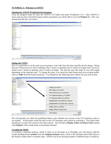
IntroductionObjectiveThe objective of this Calibration Guide is to establish a procedure that you can follow to determine theStrain Scaling Factor (SSF) and Anisotropic Strain Coefficients (ASCs) for use in the ANSYS Additive Printsoftware. The calibrated SSFs and ASCs will significantly improve the prediction accuracy of the simulationsoftware, therefore improving the chance of successful builds as well as reducing the cost of trial anderror experiments.Figure 1: SSF required for Assumed Strain simulations in Additive PrintRelease 2020 R1 - ANSYS, Inc. All rights reserved. - Contains proprietary and confidential informationof ANSYS, Inc. and its subsidiaries and affiliates.1
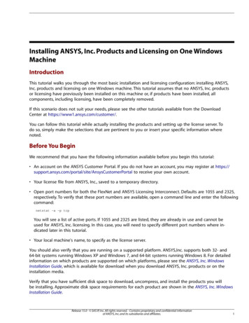
IntroductionFigure 2: SSF and ASCs required for Scan Pattern and/or Thermal Strain simulations in AdditivePrintProcedureThe calibration procedure consists of building parts, taking measurements, running simulations, andcalculating factors using a spreadsheet. You will start by building three identical parts using a differentscan pattern for each. You'll determine an initial set of SSF and ASC values using the first two scanpatterns, and then fine-tune the values with the third scan pattern. Our experience shows that the thirdscan pattern calibration step increases the accuracy of simulations for user-preferred scan patterns. Westrongly recommend the fine-tuning step that uses the third scan pattern.Here is the overall procedure:1. Build all calibration parts on the same build plateFor convenience, we recommend building all the parts on the same build plate. Use the samepart for all calibration steps but use a different scan pattern for each. The dimensions of thepart may be adjusted depending on the material, machine, and process parameters to achievea successful build. The procedure remains the same regardless of part dimensions. More detailsare available in Building the Parts (p. 7).2. Measure the dimensions of the built parts to determine distortionUsing the best measurement method available, measure the dimensions of the parts at therecommended locations of interest. Record the dimension measurements in the ANSYS-providedspreadsheet and distortions at those locations will automatically be calculated. More detailsare available in Taking Distortion Measurements (p. 11).3. Run calibration to determine an initial set of factors (for each simulation type and stress modecombination)For a chosen combination of simulation type and stress mode, run simulations of the calibrationpart in Additive Print (and ANSYS Workbench if choosing in support-only cutoff under J2 plasticity mode). Use the spreadsheet provided to calculate factors based on a distortion average2Release 2020 R1 - ANSYS, Inc. All rights reserved. - Contains proprietary and confidential informationof ANSYS, Inc. and its subsidiaries and affiliates.
from the first two scan patterns. More details are available in Running the Simulations (p. 15)and Using the Spreadsheet to Calculate SSF and ASCs (p. 27).4. Run fine-tuning calibration step with a different scan patternFor the same combination of simulation type and stress mode, run simulations with the newlycalibrated factors and use the spreadsheet to fine-tune the factors based on distortion fromthe third scan pattern.When to CalibrateThe values for SSF and ASCs depend upon the following: Material Machine Machine parameters (laser power, scan speed, layer thickness, baseplate temperature, hatch spacing,slicing stripe width, scan pattern, etc.) Simulation type performed (Assumed Strain, Scan Pattern, or Thermal Strain) Stress mode selected (linear elastic or J2 plasticity)Assuming you perform the full procedure, for each calibration you will have a complete set of valuesto be used for any simulation type/stress mode for a given material and machine. When a different material or machine is chosen, the ASC and SSF values will need to be recalibrated, regardless of the simulation type or stress mode. Even changing the material supplier for a material you have already calibratedfor may require a new calibration. If the process parameters are altered, Assumed Strain and Scan Patternbased simulations will need to be recalibrated.Important:You need to calibrate only for the type of simulation you will be performing. For example,if you know you will be performing Assumed Strain simulations only, you don’t need to buildmultiple calibration parts because scan pattern doesn't matter and you don't need to completethe calculations for ASCs, as those factors are required only for Scan Pattern and ThermalStrain simulation types. Within your Assumed Strain simulations, if you know you will beusing linear elastic stress mode only, there is no need to calibrate for J2 plasticity. See theANSYS Additive User’s Guide for further information about simulation types and stress modes.Matrix of SSF and ASCsTable 1 shows a complete matrix across different simulation types and stress modes for a certain material, A. After the full calibration process, you will record final values in the color-filled fields that areunique to that material and machine.Table 1: Complete matrix of SSF and ASCsMaterialAStress ModeLinearElasticAssumed StrainSSFScan PatternThermal StrainSSFSSFASCASCRelease 2020 R1 - ANSYS, Inc. All rights reserved. - Contains proprietary and confidential informationof ANSYS, Inc. and its subsidiaries and affiliates.3
IntroductionMaterialStress ModeAssumed StrainScan PatternASC ASC ASC zJ2 PlasticitySSF1ASC zSSFSSFASCASCASC ASC ASC z4Thermal Strain1ASC zRelease 2020 R1 - ANSYS, Inc. All rights reserved. - Contains proprietary and confidential informationof ANSYS, Inc. and its subsidiaries and affiliates.11
Cantilever Beam GeometryGeometry files of a cantilever beam part and its support, in .stl format, are available for download.The part dimensions (50 x 10 x 12.5 mm) are shown in Figure 3 (p. 5). The part and its support areshown together in Figure 4 (p. 5). The red dashed line represents the support cutoff location.Figure 3: Cantilever beam dimensionsFigure 4: Cantilever beam with supportRelease 2020 R1 - ANSYS, Inc. All rights reserved. - Contains proprietary and confidential informationof ANSYS, Inc. and its subsidiaries and affiliates.5
6Release 2020 R1 - ANSYS, Inc. All rights reserved. - Contains proprietary and confidential informationof ANSYS, Inc. and its subsidiaries and affiliates.
Building the PartsPart LayoutWe recommend you build the calibration parts on the same build. There will be three cantilever beamparts, each with a different scan pattern. The three calibration parts differ only in scan pattern. (If youwill be doing Assumed Strain simulations only, then only one part is needed and use the rotating stripescan pattern.)Implement an appropriate layout consistent with the best practice for taking gas flow direction intoaccount. Ensure there is enough space between the parts to take measurements before the parts arecut from the baseplate. The parts need to be measured while they are fixed to the plate; hence, it isimportant to keep enough space between neighboring parts.Support StructureThe support structure of the cantilever beam is provided; the parts should be built on the baseplatedirectly.Process ParametersWith the exception of the scan patterns that are described below, the parts should be built with theprocess parameters (laser power, scan speed, etc.) that you are intending to use for building your realcomponents. Make sure to use the same build parameters and scan patterns for both the part and thesupports.Scan PatternsBuild the calibration parts with the scan patterns as shown in the following figures. (For Assumed Strainsimulations, only scan pattern 3 is needed.) Scan pattern 1: bi-directional scan with 0 starting angle and 0 layer rotation angle, scan line is either0 or 180 . See Figure 5 (p. 8). Scan pattern 2: bi-directional scan with 90 starting angle and 0 layer rotation angle, scan line is either90 or 270 . See Figure 6 (p. 8) Scan pattern 3: use the scan pattern that you are intending to use for building real components. In thisguide we use a rotating stripe scan pattern with a 0 starting angle and a 67 rotation angle. See Figure7 (p. 9) There should be no extra scans such as contour scan, up-skin and down-skin, shrinkage factor, etc.Release 2020 R1 - ANSYS, Inc. All rights reserved. - Contains proprietary and confidential informationof ANSYS, Inc. and its subsidiaries and affiliates.7
Building the PartsFigure 5: Scan pattern 1 (0 , 0 )Figure 6: Scan pattern 2 (90 , 0 )8Release 2020 R1 - ANSYS, Inc. All rights reserved. - Contains proprietary and confidential informationof ANSYS, Inc. and its subsidiaries and affiliates.
Figure 7: Scan pattern 3 (rotating stripe)Important:Pay attention to the legend in Figure 5 (p. 8) and Figure 6 (p. 8). The angles refer to thedirection of the laser, not the stripe direction. The X-axis in this guide always runs parallelto the length of the cantilever. Should your machine use a different coordinate system, makesure that scan pattern 1 (0 , 0 ) results in the laser scanning parallel to the length of thecantilever. In order to achieve this, it may be necessary to set the stripe width to the lengthof the cantilever (50 mm) or more.For scan pattern 2 (90 , 0 ), the stripe width may need to be set to the width of the cantilever(10 mm) or more.Release 2020 R1 - ANSYS, Inc. All rights reserved. - Contains proprietary and confidential informationof ANSYS, Inc. and its subsidiaries and affiliates.9
10Release 2020 R1 - ANSYS, Inc. All rights reserved. - Contains proprietary and confidential informationof ANSYS, Inc. and its subsidiaries and affiliates.
Taking Distortion MeasurementsMeasurement LocationsMeasurement locations are shown in the following figures. Measurement A is along the center line of the cantilevered edge face (Y 5, X 0 mm) before cutting offthe support, as shown in Figure 8 (p. 11). This is the default measurement location. Measurement B is along the center line on the top surface of the cantilever beam (Y 5 mm, Z 12.5mm) after cutting off the support, as shown in Figure 9 (p. 12). This is an optional measurement location.Figure 8: Measurement location ARelease 2020 R1 - ANSYS, Inc. All rights reserved. - Contains proprietary and confidential informationof ANSYS, Inc. and its subsidiaries and affiliates.11
Taking Distortion MeasurementsFigure 9: Measurement location BOur experience has shown that measurement A may be a little difficult to measure. This is why weprovide an alternative measurement location, B. Measurement A is usually more sensitive to SSF, however.If you use a different geometry instead of the cantilever beam, choose one measurable location of interestbased on the geometry to perform the calibration.Measurement MethodsSeveral measurement methods are available and described below. Choose a measurement techniquewith the best resolution available.CMMIf using a Coordinate Measurement Method (CMM), measure many points in a line along the chosensurface of the cantilever beam. Find the maximum deflection for the measurement location(s). The maximum X-deflection for measurement A (see Figure 8 (p. 11)) will generally occur at the interfacebetween the beam and the supports, but we recommend comparing measurements along the height. The maximum Z-deflection for measurement B (see Figure 9 (p. 12)) will generally occur at the cantilevered end of the beam, but we recommend comparing measurements across the top surface.Record the value of the dimensions on the spreadsheet provided by ANSYS.Laser ScannerIf using a laser scanner, point cloud or scanned STL file can be obtained. Measure distortion at the Xand Z locations of interest.Caliper/Micrometer and a Digital Height GageIf using a caliper/micrometer, we recommend using calipers with fine detail extensions and a digitalheight gage to mark the height. Measure the dimension of the cantilever beam at the location of interest.This measurement technique is less accurate than the other methods and may result inaccurate distortion,SSF, and ASC values. Therefore, this is the least preferred measurement method.12Release 2020 R1 - ANSYS, Inc. All rights reserved. - Contains proprietary and confidential informationof ANSYS, Inc. and its subsidiaries and affiliates.
As a last resort, if you do not have a digital height gage, you may want to consider modifying the .stlfile to include detents at the location of interest and then use this modified geometry in your simulations.Release 2020 R1 - ANSYS, Inc. All rights reserved. - Contains proprietary and confidential informationof ANSYS, Inc. and its subsidiaries and affiliates.13
14Release 2020 R1 - ANSYS, Inc. All rights reserved. - Contains proprietary and confidential informationof ANSYS, Inc. and its subsidiaries and affiliates.
Running the SimulationsIn Additive Print, keep the following settings consistent for all simulations: Cantilever beam part (Cantilever ANSYS part.stl) Cantilever beam support (Cantilever ANSYS support.stl) Voxel size: 0.25 mm (This is a suggested value, it can be modified but should be kept consistentthroughout all simulations. We recommend you use the voxel size that you will be using for your ownpart.) Material properties, either from an ANSYS-predefined material or your customized material Process parameters (needed for Scan Pattern and Thermal Strain simulations)Use the default output options for measurement A. For measurement B, choose "Displacement aftercutoff" and specify the "Support-only Cutoff" option from the drop-down.Note:When obtaining the support-only cutoff value for measurement B in J2 plasticity mode,ANSYS Workbench/Mechanical will also need to be employed to capture the distortionand account for its value from the support cutoff process. ANSYS Workbench/Mechanicalis not required for simulations using linear elastic mode or on-plate distortion simulationsusing J2 plasticity mode.Additive Print allows you to prepare multiple simulations and queue them up to automatically run oneafter another.Simulations with the First Two Scan PatternsScan Pattern/Thermal Strain: Start with the default SSF0 1 Start with default ASC0 (1.5, 0.5, 1) Scan pattern 1 – use 0 starting angle and 0 layer rotation angle Scan pattern 2 – use 90 starting angle and 0 layer rotation angleSimulations with the Third Scan Pattern (Fine-tuning Step)Assumed Strain: For both linear elastic and J2 plasticity, start with the SSF0 1Release 2020 R1 - ANSYS, Inc. All rights reserved. - Contains proprietary and confidential informationof ANSYS, Inc. and its subsidiaries and affiliates.15
Running the SimulationsScan Pattern/Thermal Strain: For both linear elastic and J2 plasticity, start with the calibrated SSF Use the calibrated ASCs Machine Configuration - Use the scan pattern angles you used to build the third part (such as scanpattern 3 as shown in Figure 7 (p. 9)).Extracting Distortion DataFigure 10: Workflow diagram for obtaining distortion simulation values, measurements A and B (p. 16)shows a diagram of the procedure for obtaining distortion data, measurement A and measurement B.These measurements are required input values used in the ANSYS Additive Calibration spreadsheet tocalculate the Strain Scaling Factor (SSF) and the Anisotropic Strain Coefficients (ASCs). See Figure 9: Measurement location B (p. 12) for detailed instructions on using the Calibration spreadsheet.Figure 10: Workflow diagram for obtaining distortion simulation values, measurements Aand BMeasurement AFor simulation of measurement A, use the On-plate residual stress/distortion results to extract thedirectional component of displacement at the ends of the cantilever beam at the location of interest,Measurement A. Use either the ANSYS viewer in Additive Print to view the results (hover the mouseover the location of interest to get the displacement) or export the files to view in another viewer application.16Release 2020 R1 - ANSYS, Inc. All rights reserved. - Contains proprietary and confidential informationof ANSYS, Inc. and its subsidiaries and affiliates.
Measurement BLinear Elastic ModeFor simulation of measurement B in linear elastic mode, use the Displacement after cutoff Supportonly Cutoff results to extract the displacement in the Z direction along measurement B.Note:Locations of data extraction from the simulations should match the measurement locations.Figure 11: Selected points on support (left) and on cantilever beam part (right) along measurementAFigure 12: Selected points on cantilever beam along measurement B after cutoffThe data point coordinates at the locations of interest, as shown in Figures 8 (p. 11) and 9 (p. 12), are: Measurement A: (0, 5, 8.5) to (0, 5 ,12.5) Use X-displacement value Measurement B: (0, 5, 12.5) to (50, 5, 12.5) Use Z-displacement valueThe distortion on measurement A is the maximum X-displacement value.The distortion on measurement B is the maximum Z-displacement value at X 50 mm.Release 2020 R1 - ANSYS, Inc. All rights reserved. - Contains proprietary and confidential informationof ANSYS, Inc. and its subsidiaries and affiliates.17
Running the SimulationsParaview is an open-source, multi-platform data analysis and visualization application. Within Paraview,extract the distortion data by doing the following:Open the appropriate files and make it active.Edit Find Data.Figure 13: Example of how to use Paraview to find displacement value for measurement BFigure 14: Point highlighted after using the "Find Data" query18Release 2020 R1 - ANSYS, Inc. All rights reserved. - Contains proprietary and confidential informationof ANSYS, Inc. and its subsidiaries and affiliates.
J2 plasticity modeFor simulation of measurement B in J2 plasticity mode, there are two components: On-platestress/displacement and Support-only cutoff stress/displacement. On-plate stress/displacementis obtained from Additive Print at the location defined in Figure 12: Selected points on cantilever beamalong measurement B after cutoff (p. 17) followed by the procedure described above using Paraview.Support-only cutoff stress/displacement is obtained from ANSYS workbench at the same location(delineated in Figure 12: Selected points on cantilever beam along measurement B after cutoff (p. 17)).The sum of these two simulation stress/displacement values are the final values that will be used in thecalibration spreadsheet.When setting up the Additive Print for J2 palsticity mode Support-only cutoff simulation, make sureto check the Files for transfer to ANSYS Mechanical option in the Outputs section. Once the simulationis completed, export and unzip this file. Four different files are saved within the folder, as shown inFigure 15: Files for transfer to ANSYS Mechanical (p. 19). You do not need to check the Displacementafter cutoff option since this data will not be used for calibration for this particular scenario.Figure 15: Files for transfer to ANSYS MechanicalThe contents of these files are as follows:displacements.csv contains cantilever displacement values generated in Additive Print.knockdowns.ist contains knockdown factors for the entire part.model.cdb contains material properties, part/support geometry information, and boundaryconditions.states.ist contains strain information generated in Additive Print.The procedure for using ANSYS Workbench/Mechanical to obtain the Support-only cutoff displacementvalue needed to calculate measurement B (see Figure 10: Workflow diagram for obtaining distortionsimulation values, measurements A and B (p. 16)) is divided into 25 steps described in detail here. OpenANSYS Workbench, and perform the first three steps, illustrated in Figure 16: ANSYS Workbench/Mechanical setup steps 1-3 (p. 20). Drag an External Model module from Component Systems and a StaticStructural module from Analysis Systems to the Project Schematic layout (steps 1 and 2). Link Setup inExternal Model to Engineering Data and Model in Static Structural, respectively (step 3).Release 2020 R1 - ANSYS, Inc. All rights reserved. - Contains proprietary and confidential informationof ANSYS, Inc. and its subsidiaries and affiliates.19
Running the SimulationsFigure 16: ANSYS Workbench/Mechanical setup steps 1-3Right click Setup and choose Edit. in the External Model module to open a new tab, A: ExternalModel. (step 4 in Figure 17: ANSYS Workbench/Mechanical setup steps 4-6 (p. 20)). In the A: ExternalModel tab, click . under location (step 5) to select import the model.cdb file saved in the files fortransfer to ANSYS mechanical folder (step 6).Figure 17: ANSYS Workbench/Mechanical setup steps 4-6The next steps are shown in Figure 18: ANSYS Workbench/Mechanical setup steps 7-10 (p. 21). Clickthe Project tab to return to the Project Schematic page (step 7), right click the Setup cell in the ExternalModel module (step 8), choose Update from the drop-down menu, and wait until the question markon Setup becomes a green check mark (step 9). Repeat this updating procedure (right click and selectUpdate) for the Engineering Data and Model cells in the Static Structural module, respectively (step10). Green check marks will be displayed beside each cell, indicating that they have properly updated.20Release 2020 R1 - ANSYS, Inc. All rights reserved. - Contains proprietary and confidential informationof ANSYS, Inc. and its subsidiaries and affiliates.
Figure 18: ANSYS Workbench/Mechanical setup steps 7-10Double-click the Model cell in Static Structural to r
ANSYS Additive User’s Guide for further information about simulation types and stress modes. Matrix of SSF and ASCs Table 1 shows a complete matrix across different simulation types and stress modes for a certain mater-ial, A. After the full calibration process, you will re